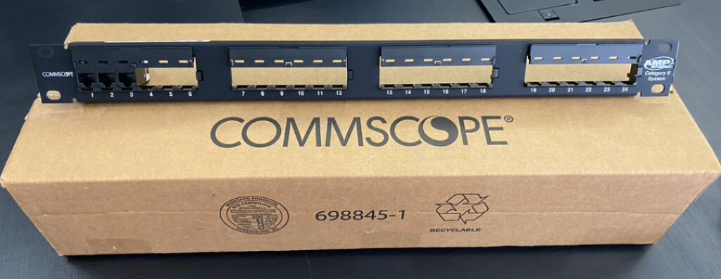
Learn what a patch panel is, what it does, and how to specify 24/48 ports, Cat6/Cat6A, loaded or unloaded models, shielding, installation, identification, and certification.
Check it out!
A patch panel is passive connecting hardware installed in a telecommunications distributor or rack to terminate, organize, identify, and administer the permanent cables of a network. Instead of connecting horizontal cabling directly to the switch, the link terminates at the patch panel and each point is activated through a patch cord between the corresponding port and the active equipment.
This architecture separates permanent infrastructure from operational patching. Cabling installed in the building remains fixed and protected; changes in users, switch ports, VLANs, equipment, or services are made in the rack without repeatedly handling the permanent termination. The patch panel therefore directly contributes to reliability, maintenance, traceability, and structured-cabling performance.
In professional designs, choosing a patch panel is not simply a decision between 24 or 48 ports. Performance category, cable type, density, termination method, shielding, rack organization, identification, patch cords, testing criteria, expansion capacity, and documentation must all be coordinated. An unsuitable or poorly installed panel can limit the entire link even when the cable itself is a higher category.
What Is a Patch Panel and What Is It Used For?
ABNT NBR 14565 classifies the patch panel as connecting hardware within a structured cabling system. This matters because the panel is not merely a mechanical support: its connections are part of the passive signal path and must preserve the performance specified for the link or channel.
In horizontal cabling, cables from telecommunications outlets are routed to the floor distributor and terminated on connecting hardware. In the rack, the patch panel provides an orderly interface for those terminations. On the front, ports are connected to the switch with patch cords; on the rear, the permanent cables are terminated or, in modular models, connectors are inserted into the panel.
A patch panel performs five main functions at the same time:
- terminates permanent cabling in a controlled manner;
- creates an accessible interface for patching and testing;
- allows each link to be identified and traced;
- protects horizontal cabling from frequent operational handling;
- organizes the transition between passive infrastructure and active equipment.
The result is a network that is easier to operate. A workstation can move to another switch port, a point can be reserved, an access point can be relocated, or a camera can be isolated for maintenance without reterminating the building cabling.
Are a Patch Panel and a Switch the Same Thing?
No. A patch panel is passive while a switch is active. The panel does not learn MAC addresses, forward Ethernet frames, create VLANs, provide switching functions, or replace network electronics. Its role is to provide manageable physical connectivity.
| Element | Patch panel | Switch |
| Nature | Passive | Active |
| Electrical power | Not required for its basic function | Required |
| Forwards Ethernet traffic | No | Yes |
| Terminates permanent cabling | Yes | No deve ser usado como terminação permanente do cabeamento horizontal |
| Supports patch-cord administration | Yes | Receives the patch cord from the panel |
| Part of passive-link certification | Yes | No faz parte do enlace permanente passivo |
| Primary function | Termination, organization, and administration | Network communication and switching |
The normal path for a network point is:
- the telecommunications outlet in the served area is connected to the horizontal cable;
- the horizontal cable reaches the rack and terminates at the patch panel;
- the patch-panel port is identified to match the served point;
- a patch cord connects that port to a switch port;
- the switch provides logical connectivity and, where applicable, PoE power.
Separating these functions simplifies troubleshooting. If a user loses connectivity, the team can check the outlet, permanent link, patch-panel port, patch cord, and active port without dismantling the entire infrastructure.
Where Does the Patch Panel Fit into the Permanent Link and Channel?
The distinction between the permanent link and the channel helps explain why the panel affects performance. Under NBR 14565, the horizontal-cabling permanent link covers the path between the telecommunications outlet and the connecting hardware at the floor distributor and may include a consolidation point. Patch cords are not part of this test model.
The channel is broader: it includes the passive infrastructure required to connect equipment end-to-end, including the patch cords and jumpers defined by the configuration. As a general reference, the standard limits the horizontal channel to 100 m and the horizontal cable of the permanent link to 90 m, subject to implementation conditions and reductions when cords exceed the model assumptions.
A poorly terminated panel is therefore not merely an aesthetic issue. It is located at one end of the permanent link. Termination defects, excessive untwisting, poor connections, category mismatch, or improper shield continuity can appear in test results and prevent the link from achieving the specified class.
This is also why connecting horizontal cabling directly to a switch, although it may appear to save a component, removes an important administration layer and exposes the permanent termination to handling that should occur through replaceable cords.
How Does Patch-Panel Termination Work?
In conventional metallic panels, each four-pair cable reaches the rear of the patch panel and is terminated on the connecting hardware corresponding to the front port. The exact termination method depends on the product and should follow the manufacturer’s instructions because geometry, tooling, cable retention, and pair organization vary among systems.
The engineering concern is to preserve pair balance up to the connection point. NBR 14565 limits pair untwisting to 13 mm at terminations for Category 5e and higher cabling and requires that only the necessary jacket length be removed. The larger the region where pairs lose their original geometry, the greater the risk of degrading transmission parameters.
Residual tension at the termination must also be avoided. The cable should be supported and organized so its weight, curvature, or bundle movement does not transfer stress to the electrical contact. The standard emphasizes protection against mechanical stress, sharp surfaces, excessive compression, and violations of minimum bend radius.
T568A or T568B on the Patch Panel?
For eight-position modular connectivity used with Categories 5e, 6, and 6A, NBR 14565 recognizes T568A and T568B. The critical point is not choosing one as universally superior, but maintaining the same pair configuration at both ends of the link and following the organization’s standard.
A connection may show electrical continuity and still be functionally incorrect if pairs are positioned inconsistently. Pinout, identification, and records should therefore be treated as quality-control items rather than installer preference.
Is the Front Port Always “RJ45”?
In everyday use, Cat5e, Cat6, and Cat6A panel ports are often called RJ45. Technically, structured cabling uses eight-position modular connectivity that complies with applicable mechanical and electrical requirements. For engineering specifications, it is more important to state category, connectivity standard, performance, and system compatibility than to rely only on the commercial term “RJ45”.
Cat5e, Cat6, and Cat6A Patch Panels: What Changes?
The patch-panel category must match the intended performance class of the system. NBR 14565 relates Category 5e to Class D, Category 6 to Class E, and Category 6A to Class EA. In terms of reference frequency range, these classes are specified up to 100 MHz, 250 MHz, and 500 MHz respectively.
| Connecting hardware | Reference class | Reference frequency range | Typical design use |
| Category 5e | Class D | up to 100 MHz | Installed base and compatible applications |
| Category 6 | Class E | up to 250 MHz | Enterprise networks with broad Gigabit Ethernet use |
| Category 6A | Class EA | up to 500 MHz | Higher-margin infrastructure, 10GBASE-T, and high-capacity points |
A categoria não é definida apenas pela etiqueta na frente do painel. O hardware de conexão precisa ter desempenho compatível com o sistema e ser instalado de acordo com as condições previstas. Um painel Category 6A não transforma automaticamente um enlace Cat6 em Cat6A, assim como um cabo Cat6A não compensa um patch panel Category 6.
The standard itself establishes backward-compatibility logic: when components from different categories are combined, resulting performance is limited by the lowest-category component. This should be reflected in specifications, bills of materials, equivalency criteria, and incoming inspections.
For new projects, the choice between Cat6 and Cat6A should follow application and lifecycle requirements. The dedicated article on Cat6 vs. Cat6A explores speed, 10GBASE-T, temperature, PoE, and infrastructure impact in greater depth.
24-Port or 48-Port Patch Panel: How Should It Be Sized?
24-port and 48-port densities are very common, but the decision should not simply “match” the number of switch ports. The panel represents installed physical links; the switch represents active ports. Not every point needs to be active simultaneously, and the infrastructure should account for expansion, contingency, and standardization.
A 24-port patch panel often improves visual readability and maintenance, while a 48-port panel can increase density and reduce rack-unit use. However, 48-port models may concentrate more patch cords in the same frontal area and require greater organizational discipline. Physical height should not be assumed: different constructions exist and the design should verify the dimensions of the specified model.
| Criterion | 24 ports | 48 ports |
| Density | Lower | Higher |
| Port visibility and access | Generally simpler | May require more organizational discipline |
| Number of panels for many points | Higher | Lower |
| Patch-cord concentration | Lower por painel | Higher por painel |
| Segmentation flexibility | High | High, desde que bem identificada |
| Typical use | Racks of different sizes | Higher-density environments or limited rack space |
Size for Installed Points, Not Only Active Ports
If a floor has 86 permanent links, sizing the infrastructure only around the 72 switch ports currently required creates an inconsistency. All 86 cables need to be terminated and administered whether or not they are active at that moment. The design should consider the total number of physical points, desired spare capacity, and expansion standard.
It can also be useful to organize panels by floor, zone, system, or functional area when this improves maintenance. The objective is not to create complex coding but to reduce the time required to locate the origin and destination of each link.
Loaded, Unloaded, and Modular Patch Panels
The market commonly distinguishes loaded and unloaded panels. In a loaded panel, connecting elements are part of the panel assembly. In an unloaded panel, also called modular in many catalogs, modules or keystones are installed as needed.
Loaded Patch Panel
A loaded panel tends to provide a homogeneous and predictable configuration. All ports belong to the same construction system and are normally specified for the same category. This can simplify assembly, bills of materials, and standardization in large installations.
The tradeoff is lower physical flexibility for replacing a single module or mixing interfaces. A failure may require intervention according to the manufacturer’s construction, and port density and layout are determined by the panel itself.
Unloaded or Modular Patch Panel
An unloaded patch panel provides openings for compatible modules. This allows only the required positions to be populated, individual modules to be replaced, and, when supported by the system, categories or functions to be differentiated by component.
Modularity does not eliminate performance requirements. The panel + module + cable + patch-cord assembly must be compatible with the intended class. Mechanical retention, rear access, identification, and dimensional compatibility should also be verified. “Universal keystone” should not be treated as automatic technical equivalency.
Pass-Through Patch Panel
Some systems use pass-through panels with front and rear couplers. They can be useful in specific applications, laboratories, racks with preterminated cables, or certain modular architectures. The decision should consider the number of additional connections introduced into the channel, coupler category, maintenance, and testing criteria. Additional interfaces are not necessarily a problem, but they must be accounted for in the adopted performance model.
Shielded Patch Panel: When Should It Be Used?
A shielded patch panel makes sense when it is part of a shielded channel designed as a system. NBR 14565 is explicit: when shielded cabling is used, all components forming the shielded channel must preserve shielding, and terminations must maintain continuity through suitable low-impedance connections.
This means it is not enough to install F/UTP, U/FTP, or S/FTP cable and select any metal panel. Connectors, modules, panel, patch cords, and the grounding/equipotential-bonding method must be compatible. A discontinuity can compromise the intended electromagnetic function.
Shielding should also not be used as a late correction for poor pathway and space design. Proper separation, routing, electromagnetic environment, grounding, and installation remain relevant. The choice between unshielded and shielded systems should begin with analysis of the environment and performance requirements.
Grounding and Equipotential Bonding of the Shielded Panel
NBR 14565 relates grounding and equipotential bonding to ABNT NBR 5410 and NBR 5419. In shielded systems, racks and cabinets are part of the telecommunications infrastructure bonding strategy. Continuity should be designed and verified; it should not depend on incidental contact between painted metal parts or improvised field solutions.
High Density: More Ports Do Not Always Mean a Better Design
NBR 14565 establishes that connecting hardware should provide efficient density without impairing management. This principle is especially important in racks with large numbers of panels.
High density can reduce vertical rack use but increases the concentration of cables and patch cords. If the rack front becomes a mass of crossed cords, space savings lose operational value. The design should balance density with access, label readability, working space, bend radius, and the ability to intervene without disconnecting neighboring ports.
In critical environments, the cost of an additional rack unit should be compared with the recurring cost of difficult maintenance, patching errors, and downtime. The most compact solution does not always have the lowest lifecycle cost.
Patch Panel, Switch, and Organizers: How Should the Rack Be Arranged?
There is no single universal sequence of patch panel, organizer, and switch that applies to every rack. The best arrangement depends on density, patch-cord type, amount of equipment, cable flow, ventilation, rear access, redundancy, and the organization’s operating standard.
The objective is to minimize crossings, keep ports visible, allow equipment replacement, and reduce excess patch-cord length. In some layouts, panels and switches are interleaved; in others, panels are grouped and cords are routed through vertical and horizontal organizers. Both approaches can work when properly sized.
Design considerations include:
- usable rack width and depth;
- number and density of panels;
- position of switches and other active equipment;
- horizontal and vertical organizers;
- permanent-cable entry and strain relief;
- power and telecommunications pathways;
- front and rear maintenance access;
- ventilation of active equipment;
- spare space for growth;
- patch-cord lengths and routes.
The article Network Rack: Organization, Components, and Best Practices addresses the rack as a whole; here, the focus remains on the role of the patch panel within that architecture.
Patch Cords: Why Do Length and Quality Matter?
The patch cord is the flexible component used to connect the patch-panel port to the switch or other connecting hardware. It is replaceable and should absorb operational changes that should not be made to horizontal cabling.
Channel quality also depends on these cords. NBR 14565 includes patch cords in the channel model and requires their loss contribution to be considered. Excess length creates rack clutter and also consumes channel margin. Cords that are too short, on the other hand, may be subjected to tension and improper bends.
The design and operations teams should therefore use standardized lengths compatible with the actual layout. Buying every patch cord in the same length for convenience often creates coiled excess, obstructed organizers, and difficulty identifying routes.
How Should Patch-Panel Ports Be Identified?
Identification turns the rack into manageable infrastructure. Each port should allow the link to be traced to its outlet or field device, and that identifier should match drawings, rack maps, certification reports, and as-built documentation.
NBR 14565 requires connecting hardware to provide means of identification and refers administration to ISO/IEC 14763-1. It also requires cabling that is physically similar but differs in category, impedance, or characteristics to be identified so that it cannot be confused.
A scheme may combine, for example:
- room or distributor identification;
- rack identification;
- patch-panel identification;
- port number;
- telecommunications-outlet code;
- floor, zone, or served area;
- special function, when truly necessary.
The coding should be simple enough to be consistently used. A sophisticated identifier that nobody maintains loses value. In large installations, the relationship among ports, cables, assets, and services may be maintained in inventory systems, DCIM/IPAM, or another source of truth, provided governance exists to record changes.
Patch Panels in PoE Networks
The patch panel does not generate PoE. Power is supplied by active equipment, such as a PoE switch, or by suitable power-insertion equipment. However, current flows through the passive channel connections, so contact quality, termination, component compatibility, and conductor gauge remain relevant.
In higher-power applications or environments with high density of powered devices, the design should evaluate not only the switch but also the cabling, cable concentration, operating temperature, connectors, and physical infrastructure. NBR 14565 highlights conductor gauge and voltage drop when power is delivered over balanced cabling.
Poor terminations can increase local resistance and create hot spots. This reinforces the need to install the panel using the tooling, preparation, and method specified by the manufacturer and to accept the installation through testing, not only visual inspection.
Patch Panels for Enterprise Wi-Fi
Wireless access points depend on wired infrastructure for data and frequently for PoE. NBR 14565 recommends at least Class EA/Category 6A for balanced cabling serving wireless coverage areas when higher data rates and greater power capacity are required.
In this context, the patch panel must match the category specified for the link. Spare ports should also be consistent with the coverage grid and potential future access points. An undersized panel may seem irrelevant during initial installation but becomes a problem when wireless density needs to increase.
The patch panel does not replace Wi-Fi design. It implements, in the rack, part of the physical infrastructure required for the designed points to be connected and administered.
Patch Panels in IP CCTV, Access Control, and Automation
IP cameras, controllers, intercoms, automation devices, and other Ethernet equipment may also terminate on patch panels when they are part of the structured infrastructure. This allows links to be tested, identified, and administered consistently.
In IP CCTV, for example, the panel port can be linked to the camera identifier and the point’s certification report. A fault can then be isolated among the device, patch cord, switch, and permanent link. In access control, the same logic supports maintenance without losing the relationship between physical infrastructure and the served device.
The panel should not become a legend for every building system through excessively complex codes. Link identification should remain stable; operational attributes that change frequently can remain in the management system.
How Should a Patch Panel Be Specified in a Design?
A technically verifiable specification describes assembly performance and requirements rather than simply copying a brand and commercial code. The objective is to enable comparable procurement and objective acceptance.
A design narrative or specification may define, as applicable:
- performance category compatible with the link class;
- minimum number of ports and spare-capacity strategy;
- loaded, unloaded, or modular construction where technically justified;
- compatibility with the adopted connectivity standard;
- shielded or unshielded solution;
- shield continuity and equipotential-bonding provisions where applicable;
- rack or cabinet installation and relevant dimensional requirements;
- permanent port identification;
- cable organization and strain-relief provisions;
- environmental range compatible with the application;
- compliance with applicable requirements for connecting hardware;
- manufacturer technical documentation;
- testing and acceptance criteria for the installed link.
For the connecting hardware covered by Section 11, NBR 14565 specifies performance across an operating range of –10 °C to +60 °C and protection against physical damage, direct moisture, and corrosive elements. This does not mean any panel can be installed outdoors; the enclosure and environment must be appropriate for the application.
Procurement: How to Compare Patch-Panel Proposals
Comparing only “24-port Cat6 Patch Panel” can result in technically different proposals. Two products with the same short description may differ in termination system, construction, cable retention, density, identification, shielding, accessories, documentation, and integration with other components.
In technical bid leveling, verify at least:
- declared category and performance evidence;
- reference standard for the connecting hardware;
- type and number of ports;
- compatibility with specified cable and connectivity;
- termination method and required tool;
- identification system;
- rear cable management and retention;
- grounding requirements for shielded models;
- required accessories included or sold separately;
- documentation, warranty, and traceability;
- compatibility with field testing for the specified category.
A small unit saving on the panel may disappear if the product requires unplanned accessories, increases installation time, makes maintenance harder, or causes certification failures. The correct analysis is installed cost and lifecycle risk.
Technical bid leveling prevents a low price from hiding differences in performance, accessories, or installation requirements.
Owner’s Engineering can support specification, equivalency analysis, proposal comparison, incoming inspection, and compliance control during implementation.
Can Brands Be Mixed?
Performance standards do not, in principle, require the entire channel to use a single brand. The essential requirement is that the installed system meet the performance of the specified class. Manufacturers may, however, establish specific conditions for extended warranties or certified channel systems.
In open procurement, engineering should separate standards compliance from a commercial warranty program. If a manufacturer system warranty is a contractual requirement, it should be explicitly stated and justified. If the requirement is verifiable performance, equivalency should be analyzed using technical criteria and confirmed on the installed link.
It is also important to remember that NBR 14565 establishes that when different categories are combined, the performance of the lowest-category component prevails. Mixing components cannot therefore be used to claim a channel class higher than its weakest component.
Installation: What Most Often Causes Patch-Panel Problems?
Most failures do not come from the panel concept itself, but from execution. The hardware may be suitable and the link may still fail because of incorrect installation.
Excessive Pair Untwisting
For Category 5e and higher, NBR 14565 limits pair untwisting at termination to 13 mm. Opening pairs too far before the connection point alters the geometry that controls crosstalk and balance.
Removing Too Much Jacket
The standard recommends removing only the jacket needed for termination. A large rear area with exposed pairs loses mechanical protection and is more susceptible to deformation during organization.
Applying Tension to the Contacts
The cable bundle should have independent support. Panel contacts should not carry the cable’s weight or tension.
Excessively Compressing Cable Bundles
Ties and organizers should not deform the cable. Excessive compression can alter geometry, increase mechanical stress, and make maintenance more difficult.
Ignoring Bend Radius
Rear entry should allow the cable to change direction while respecting manufacturer and design requirements. Forced bends immediately after termination indicate an inadequate layout.
Using Incompatible Tools or Procedures
The termination method is part of the construction system. Improvising tools, force, or sequence can damage contacts or leave conductors improperly seated.
Identifying Only After Assembly
When dozens of cables reach the rack without controlled identification, the risk of mixing positions increases significantly. The identifier should follow the cable during installation and be validated at handover.
How Does Certification Detect Patch-Panel Problems?
Field certification evaluates the installed link, not just cable on a reel or the patch panel in isolation. Because the panel is at one end of the permanent link, its termination affects results.
Annex A of NBR 14565 references testing of installed balanced cabling in accordance with IEC 61935-1. Acceptance characteristics include wire map, continuity, return loss, insertion loss, NEXT, PSNEXT, propagation delay, and other parameters determined or calculated according to the test type.
Termination failures near the patch panel may appear as degraded NEXT or return loss, open pairs, reversals, or other wire-map problems. Diagnosis should use tester data and termination inspection; simply “redoing it until it passes” without recording the cause discards important knowledge about installation quality.
For more detail on measurement criteria, see Test Parameters for Twisted-Pair Cable Certification and Network Cabling Certification.
Patch-panel acceptance depends on installed-link performance, not only on the component data sheet.
Ensaios de campo permitem verificar wiremap, perda de inserção, NEXT, perda de retorno and demais parâmetros aplicáveis, vinculando cada resultado ao enlace físico correspondente.
Does the Patch Panel Need to Be Individually “Certified”?
The product should have specifications and performance evidence compatible with its declared category, but project acceptance does not end with a catalog certificate. For delivered infrastructure, what matters is demonstrating the performance of the installed link under actual project conditions.
This distinction avoids two common errors: accepting a poor link because the components are from a “certified brand,” or rejecting a technically equivalent product without evaluating compliance and final performance. Product documentation and field testing serve complementary functions.
Patch Panels in Retrofit: Keep or Replace?
In existing networks, the first decision should not be to remove every panel. Category, physical condition, occupancy, termination standard, available documentation, and actual link performance should first be identified.
A panel can be preserved when its category and condition are compatible with the retrofit objective and the links can be validated. Replacement is more likely when ports are damaged, category is insufficient, identification cannot be recovered, terminations are degraded, the panel is incompatible with the new architecture, or required standardization cannot be achieved otherwise.
Retrofit is also an opportunity to correct management problems: abandoned ports, cables with unknown origin, unused patch cords, inconsistent rack occupancy, and divergent documentation. Before replacing active equipment, mapping passive infrastructure prevents old defects from being transferred to the new network.
Is an Unloaded Patch Panel Better for Retrofit?
It can be, but not as a universal rule. Modularity makes it easier to replace individual connectors and gradually populate new ports, which is useful in phased interventions. However, if the objective is to rebuild dozens of homogeneous terminations, a loaded system can provide equally suitable operational standardization.
The choice should consider logistics, spare inventory, labor, accessibility, compatibility, number of ports, and the future standard. “Modular” is a construction characteristic, not an automatic synonym for higher performance.
Technical Acceptance of the Patch Panel and Rack
Acceptance should cross-check physical inspection, documentation, and test results. A visually organized rack may contain poorly terminated links; an electrically compliant installation may be so poorly identified that maintenance becomes risky.
An acceptance procedure should verify:
- installed model and category against the approved design;
- number of ports and spare capacity;
- panel mounting and integrity;
- rear cable support and organization;
- bend radius and absence of visible mechanical tension;
- termination and workmanship standard;
- shield continuity and equipotential bonding where applicable;
- front and rear identification;
- correspondence with outlets, drawings, and rack map;
- certification reports associated with the correct identifiers;
- record of spare ports and decommissioned points;
- update of the as-built and inventory.
Traceability is essential. A “Pass” report without identification that allows the physical link to be located has limited operational value.
Administration and Change Management
After handover, the main risk becomes loss of operational discipline. Patch cords are moved, switches are replaced, points change function, and new ports are activated. If changes are not recorded, the rack gradually returns to an unknown-infrastructure state.
NBR 14565 requires records of components, pathways, distributors, and spaces to be maintained and recommends software-based systems in large installations. Management may be simple or integrated with a source of truth, but it must reflect field reality.
The best identification remains valid when the user changes. Associating a port only with a person’s name or temporary equipment creates rework. Stable physical identifiers should be related at another management layer to services and assets that may change over time.
How to Choose a Patch Panel: Decision Matrix
| Design question | Decision influenced |
| Which class/category must the link achieve? | Cat5e, Cat6, Cat6A, or another compatible solution |
| How many links will be terminated? | Number and density of panels |
| What expansion is expected? | Spare ports and future space |
| Is a shielded system required? | Compatible panel, connectors, patch cords, and equipotential bonding |
| Does the environment require modularity? | Loaded, unloaded, or pass-through |
| Is there high density in the rack? | 24/48 ports, organizers, and access strategy |
| Is large-scale PoE used? | Connection quality, conductor gauge, temperature, and organization |
| How will links be administered? | Labels, coding, port map, and record system |
| What is the acceptance criterion? | Test category, report format, and traceability |
| Is a system warranty required? | Compatibility with manufacturer rules and contractual documentation |
The matrix prevents selecting the panel before understanding requirements. In a well-structured specification, the product is a consequence of the design rather than its starting point.
Common Errors When Specifying and Installing Patch Panels
Buying Only by Port Count
Twenty-four or 48 ports do not indicate category, construction, compatibility, termination method, shielding, or performance.
Specifying Cat6A and Accepting a Cat6 Panel
The lowest-category component limits resulting performance. Replacing only the cable does not create a Class EA link.
Treating a Shielded Panel as Just Any Metal Part
Functional shielding depends on continuity among components and proper equipotential bonding.
Running Horizontal Cable Directly to the Switch
This mixes permanent termination with operational patching, reduces organization, and increases the risk of damage to fixed cabling.
Designing the Rack Without Considering Rear Cabling
The front may look organized while the rear is compressed, unsupported, or forced into incompatible bends.
Using Excessively Long Patch Cords
In addition to consuming channel margin, excess cord length worsens identification, access, and maintenance flow.
Accepting Only a Continuity Test
Wire map is necessary but does not by itself prove cabling-category performance. Testing should correspond to the specified acceptance criterion.
Failing to Link the Report to the Physical Port
Certification without traceability makes it impossible to know which link was actually measured and complicates future audits.
Failing to Plan Spare Ports and Expansion Space
Growth then occurs through improvised panels, nonstandard switches, and cords crossing the rack.
Checklist for Design, Installation, and Acceptance
Before finalizing the specification or accepting the installation, confirm:
- required link category and class;
- total number of points, not only active ports;
- spare capacity and expansion strategy;
- 24/48-port density compatible with maintenance needs;
- justified loaded, unloaded, or modular construction;
- shielded or unshielded solution consistent with the channel;
- compatibility among cables, connectors, panel, and patch cords;
- adopted and documented T568A/T568B standard;
- controlled untwisting and termination preparation;
- cables supported without tension on contacts;
- rear and front rack organization;
- permanent and consistent identification;
- port-to-outlet/point documentation;
- defined certification criteria;
- test results associated with the correct identifiers;
- updated drawings, rack map, and as-built;
- process for recording future changes.
Final Considerations
A patch panel is relatively simple when viewed in isolation, but its role in the system is strategic. It forms the manageable boundary between permanent cabling and active equipment, contributes to link performance, centralizes identification, and allows changes to occur without degrading fixed infrastructure.
The choice should therefore not be reduced to “24 or 48 ports.” Category, connectivity, density, shielding, termination, organization, identification, PoE, testing, and documentation need to be coordinated with the design. When these criteria are defined before purchase, the panel stops being a generic rack item and fulfills its role as connecting hardware within a verifiable and manageable structured cabling system.
Patch panels, port density, category, rack organization, and certification criteria should be coordinated before purchase. A detailed design prevents infrastructure from being sized only from a bill of materials.
Technical definition also enables proposal leveling and installation acceptance based on performance, identification, and link traceability.
Structure These Requirements in the Structured Cabling Design
Technical References
[1] BRAZILIAN ASSOCIATION OF TECHNICAL STANDARDS. ABNT NBR 14565:2019 — Structured cabling for commercial buildings. Rio de Janeiro: ABNT, 2019. Available at: https://www.abntcatalogo.com.br/
[2] BRAZILIAN ASSOCIATION OF TECHNICAL STANDARDS. ABNT NBR 16415 — Pathways and spaces for structured cabling. Rio de Janeiro: ABNT. Available at: https://www.abntcatalogo.com.br/
[3] BRAZILIAN ASSOCIATION OF TECHNICAL STANDARDS. ABNT NBR 16869 Series — Structured cabling: planning, installation, testing, and configurations. Rio de Janeiro: ABNT. Available at: https://www.abntcatalogo.com.br/
[4] INTERNATIONAL ORGANIZATION FOR STANDARDIZATION; INTERNATIONAL ELECTROTECHNICAL COMMISSION. ISO/IEC 11801-1 — Information technology — Generic cabling for customer premises — Part 1: General requirements. Available at: https://www.iso.org/standard/66182.html
[5] INTERNATIONAL ORGANIZATION FOR STANDARDIZATION; INTERNATIONAL ELECTROTECHNICAL COMMISSION. ISO/IEC 14763-1 — Information technology — Implementation and operation of customer premises cabling — Part 1: Administration. Available at: https://www.iso.org/standards.html
[6] INTERNATIONAL ELECTROTECHNICAL COMMISSION. IEC 61935-1 — Specification for the testing of balanced and coaxial information technology cabling — Part 1: Installed balanced cabling. Available at: https://webstore.iec.ch/
Frequently Asked Questions
A patch panel is passive connecting hardware installed in racks or distributors to terminate, organize, identify, and administer permanent structured cabling. Panel ports are connected to switches by patch cords.
It separates permanent cabling from operational patching, centralizes terminations, identifies links, and facilitates testing, moves, maintenance, and network expansion.
No. A patch panel is passive and organizes physical connections. A switch is active, requires electrical power, and forwards Ethernet traffic. A patch cord normally connects each active patch-panel port to the corresponding switch port.
It depends on the number of links, rack density, and maintenance strategy. 48-port panels increase density; 24-port models generally simplify access and organization. The design should also consider expansion and patch-cord distribution.
It is a panel that receives separately installed modules or keystones. It provides modularity and individual connector replacement, but the assembly must maintain mechanical compatibility and performance with the specified category.
Cat6 hardware is associated with Class E, specified up to 250 MHz, while Cat6A is associated with Class EA, up to 500 MHz. For a link to be Cat6A, cable, connecting hardware, patch cords, and installation must be compatible; a Cat6 component limits overall performance.
No. Performance category and shielding construction are different characteristics. Cat6A systems exist with different constructions. When a shielded channel is adopted, all relevant components must preserve shield continuity and the specified equipotential bonding.
ABNT NBR 14565 limits pair untwisting to 13 mm when terminating Category 5e and higher cabling and recommends removing only the jacket necessary for termination.
In shielded systems, shield continuity and equipotential bonding need to be properly addressed, including racks and cabinets according to the design. In unshielded panels, metallic mechanical mounting should not be confused with a channel-shielding requirement.
Yes. In horizontal cabling, the connecting hardware at the distributor is part of the permanent link. Field certification evaluates the installed link, so patch-panel quality and termination affect parameters such as wire map, return loss, insertion loss, and crosstalk.
There are physical situations where a direct connection can be built, but in enterprise structured cabling the patch panel creates a manageable separation between the permanent link and active electronics. Eliminating this interface reduces flexibility, maintainability, and traceability and should be technically justified rather than treated as a default.
Each port should use a permanent identifier that relates it to the link and corresponding outlet or point. The same code should appear in records, drawings, rack maps, and certification reports, with a management process for recording changes.
Complementary Technical Materials
Related Solutions
- Structured Cabling: design, implementation, certification, and management
- Industrial Structured Cabling
- Integrated Engineering for Data Centers
Related Services
Main Content on the Topic
- Complete Guide to Structured Cabling
- Structured Cabling Components
- Network Rack: organization, components, and best practices
- Types of Network Cables
- Cat6 vs. Cat6A
