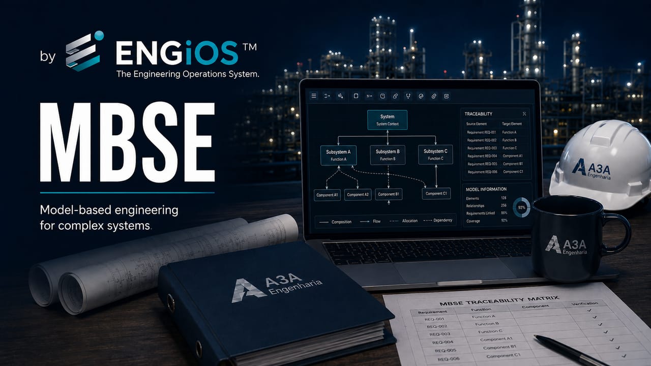
Understand MBSE — Model-Based Systems Engineering — for complex systems: requirements, architecture, SysML, interfaces, traceability, V&V, change management, and the Digital Thread.
Check it out!
Model-Based Systems Engineering (MBSE) is the formalized application of models to support requirements, architecture, analysis, integration, verification, and validation throughout a system life cycle. Instead of keeping project logic distributed primarily across documents, spreadsheets, independent diagrams, and tacit knowledge, MBSE seeks to establish a structured model in which system elements and their relationships can be traced, analyzed, and updated coherently.
The approach is particularly useful for complex systems, where functional and non-functional requirements are distributed across multiple disciplines, suppliers, subsystems, and interfaces. In these environments, the principal advantage of MBSE is not to “draw better diagrams,” but to reduce inconsistencies among needs, requirements, architecture, interfaces, decisions, tests, and evidence.
MBSE should be understood as a way of performing Systems Engineering with greater information integration. It does not replace engineering, governance, or professional judgment; nor does it require every project to adopt the same language, tool, or level of formality. The method should be proportional to system complexity and risk.
MBSE Is Not Simply the Use of a Modeling Tool
An organization can own modeling software and still work essentially through documents. What characterizes MBSE is the role of the model as a structured source of information for Systems Engineering activities.
INCOSE defines MBSE as the formalized application of modeling to support system requirements, design, analysis, verification, and validation beginning in the conceptual design phase and continuing throughout later life-cycle phases. This definition shifts the focus from the tool to the engineering process.
| Predominantly document-based approach | Model-oriented approach |
|---|---|
| Requirements maintained in independent files | Requirements connected to model elements and relationships |
| Architecture described in multiple documents | Architecture represented through views derived from a common structure |
| Interfaces controlled in isolated records | Interfaces related to the elements they connect |
| Change impact reconstructed manually | Impact analyzed through modeled dependencies |
| Tests linked through spreadsheets and team memory | Verification and validation traced to requirements |
The benefit becomes visible when a requirement change allows the team to identify affected functions, components, interfaces, and verification cases without manually searching dozens of documents.
What Changes When the Model Becomes Part of Engineering
In a traditional approach, a diagram is often a final product: someone interprets information, draws the figure, and publishes the document. In MBSE, the graphical view represents elements that already exist in a structured model. Different diagrams can therefore show coherent subsets of the same information base.
A functional block may appear in an architecture view, an interface analysis, and a requirements-allocation matrix. If the element changes, these representations should reflect the same logical reality.
This principle is close to the Digital Engineering concept of an authoritative source of data. The purpose is not to eliminate documents, but to prevent each document from becoming a competing source of truth.
MBSE Within Systems Engineering
Systems Engineering connects stakeholder needs, requirements, architecture, interfaces, integration, verification, and validation. MBSE adds a structured representation layer that helps preserve these relationships during development.
ISO/IEC/IEEE 15288:2023 establishes system life-cycle processes but does not prescribe a specific methodology or language. This distinction matters: MBSE can support those processes, but it is neither a requirement of the standard nor a replacement for Systems Engineering processes.
A project may apply MBSE to only part of the life cycle, such as architecture and verification, or may build a broader integrated environment. The appropriate level depends on the value produced by modeling compared with the effort required to maintain it.
From Documents to Models: Changing the Unit of Information
In a document, the unit of information is often a paragraph, table, or drawing. In a model, the unit becomes an engineering object: a requirement, function, component, interface, scenario, risk, test case, or another element defined by the metamodel.
Each object may have attributes and relationships. A requirement may be related to the need that originated it, the function that satisfies it, the responsible component, and the verification case that demonstrates compliance.
A typical traceability chain connects Need → Requirement → Function → Architecture Element → Interface → Verification → Evidence, while technical risks may be related to any of these objects. This structure improves impact analysis when upstream needs change.
Model, Diagram, and Documentation Are Not Synonyms
One of the most common MBSE mistakes is confusing a model with a diagram. A diagram is a view. The model is the structure of elements, properties, and relationships that exists independently of that view.
Two diagrams can show the same element in different contexts. A matrix can be generated from the same relationships. A requirements table can also be extracted from the model without duplicating the underlying data.
Documentation continues to exist because contracts, approval processes, audits, and handover frequently require formal documents. The difference is that part of this documentation can be generated or updated from the model, reducing divergence among representations.
The Role of the Metamodel
A metamodel defines the types of elements and relationships allowed in the modeling environment. It functions as the grammar of engineering information.
Without a coherent metamodel, each modeler may use elements differently, producing an environment that is visually sophisticated but semantically inconsistent. Implementing MBSE therefore requires conventions defining what constitutes a requirement, function, component, interface, risk, scenario, and verification element, and how these objects may relate.
The NASA Systems Modeling Handbook emphasizes the need to organize the model, metamodel, relationships, and Systems Engineering products. Semantic consistency is a prerequisite for useful analysis and traceability.
SysML and Other Modeling Languages
SysML — Systems Modeling Language — is a widely used language for systems modeling. It provides constructs for representing structure, behavior, requirements, parametric relationships, and other aspects of multidisciplinary systems.
In 2025, the Object Management Group completed formal adoption of SysML v2, designed to improve precision, expressiveness, consistency, interoperability, and extensibility compared with previous generations. SysML v2 also strengthens textual representation and API-based integration mechanisms, which are relevant to Digital Engineering ecosystems.
MBSE, however, is not synonymous with SysML. A program may use another language, a custom metamodel, or a combination of technologies, provided the model supports the engineering processes the organization intends to control.
When SysML Adds Value — and When It May Be Excessive
SysML tends to add value when a system has many relationships among requirements, functions, states, interfaces, and physical or logical elements. It also helps when multiple teams need to work through a common language and when analyses and documentation must be generated from the same model.
For a small project with few interfaces and a low cost of change, a full MBSE infrastructure may create more effort than benefit. In such situations, strong requirements, architecture, and interface management may solve the problem without a formal MBSE deployment.
The criterion should be risk and complexity, not technology trends.
Requirements in MBSE
Requirements Management already requires definition, traceability, change control, and acceptance criteria. In MBSE, those requirements become directly related to model elements.
This allows derivation, decomposition, allocation, and satisfaction to be represented explicitly. A system requirement may derive subsystem requirements; these can be allocated to architecture blocks; verification cases can demonstrate compliance.
| Relationship | Question it must answer |
|---|---|
| Need → requirement | Why does this requirement exist? |
| Requirement → derived requirement | What technical condition originated from the higher-level need? |
| Requirement → element | Who or what is responsible for satisfying it? |
| Requirement → interface | Which boundary is affected? |
| Requirement → verification | How will compliance be demonstrated? |
This traceability reduces the risk of orphan requirements and tests that do not correspond to a real need.
When requirements, interfaces, and critical decisions are scattered among independent documents, impact analysis becomes slow and prone to inconsistencies. A common technical source makes it possible to trace changes before they propagate into design, procurement, and implementation.
Model-Oriented Architecture
Systems architecture organizes functions, elements, relationships, and structuring decisions. In MBSE, architecture can be represented through multiple views without losing the relationships among objects.
A functional view shows behavior and functional decomposition. A logical view shows services and responsibilities. A physical view shows equipment, software, networks, facilities, or other resources. An interface view highlights exchanges and dependencies.
ISO/IEC/IEEE 42010:2022 distinguishes architecture from architecture description and formalizes concepts such as stakeholders, concerns, viewpoints, and model kinds. This logic is compatible with MBSE because no single view can represent every system concern.
Viewpoints: Architecture Must Address Different Concerns
Operations, maintenance, cybersecurity, availability, performance, integration, and implementation do not require the same view. A single diagram containing everything usually becomes unreadable.
Viewpoints define how specific concerns will be represented. The model preserves the relationships; the views select the appropriate subset.
This separation improves technical review. A security team can analyze boundaries and flows; operations can review modes and scenarios; infrastructure can verify physical allocation. All teams work with related elements rather than independent drawings.
Interfaces in the Model
Interfaces are one of the strongest MBSE use cases because they concentrate integration risks. An interface may have an origin, destination, type, protocol, flow, data, electrical characteristic, responsibility, state, requirement, and test evidence.
Modeling these relationships enables interface matrices and helps identify elements with undefined connections, interfaces without requirements, or boundaries that still lack an owner.
In projects involving multiple suppliers, this visibility turns contractual boundaries into controllable engineering objects.
Behavior, Scenarios, and States
Systems are not only structures. They perform behaviors and change state. Models can represent sequences, activities, states, and interactions among components.
This is particularly useful for normal, degraded, maintenance, contingency, and emergency modes. An availability requirement may appear satisfied during normal operation yet fail when a component is unavailable.
Modeling scenarios helps anticipate these conditions and define what must be validated in the operational environment.
Parametrics and Analysis
Models may incorporate parametric relationships or connect to specialized analysis tools. Depending on the domain, this can support performance, mass, power, availability, capacity, reliability, cost, or other analyses.
The value appears when analyzed parameters remain related to the current configuration and system requirements. An architecture change can trigger a new analysis using updated data, reducing the risk of relying on a spreadsheet based on an obsolete configuration.
Not every model needs to be executable. The level of formalization should reflect the decision the model is intended to support.
MBSE and Change Management
Changes are inevitable in complex systems. The challenge is identifying the complete impact before approving them.
Engineering Change Management should assess effects on scope, requirements, interfaces, cost, schedule, and testing. MBSE strengthens this analysis by making dependencies explicit.
A component replacement may affect power consumption, communications, software, thermal dissipation, availability, security, maintenance, and documentation. When these relationships are modeled, the team can map the effects more consistently.
Configuration Management and the Model Baseline
Models also require configuration governance. Without version control and baselines, an MBSE environment can become as ambiguous as an uncontrolled document collection.
The baseline should identify which configuration was approved for a given phase, review, or decision. Changes should record who changed what, why, when, and which elements were impacted.
Contracts also need to define which model version is the reference for each delivery. A modeling platform does not eliminate the need for formal documentation and configuration management.
Model-Oriented Verification and Validation
One of the most valuable MBSE applications is connecting requirements to verification methods and cases. This supports coverage analysis: which requirements have a defined method, which have been verified, which failed, and what evidence supports the result.
Validation operates at another level. It evaluates whether the system satisfies the need in its intended use. Modeled operational scenarios help structure validation procedures that test real workflows and degraded conditions.
This integration is consistent with NASA-HDBK-1009A, which relates modeling to Technical Requirements Definition, Product Verification, and Product Validation.
From a Verification Matrix to a V&V Model
In document-centric projects, the verification matrix is commonly a spreadsheet. In MBSE, the same logic can be represented through relationships among requirement, method, case, configuration, and evidence.
This helps identify gaps before testing begins. A requirement without a verification method is an engineering problem; a test case without a requirement may indicate activity with no clearly defined purpose.
Governance of requirements, evidence, and acceptance criteria converts this traceability into objective acceptance conditions.
MBSE and the Digital Thread
Digital Thread describes continuity of information and relationships throughout the life cycle. MBSE can be a central element of that continuity because it connects Systems Engineering decisions to design, simulation, configuration, test, and operational data.
The concept does not mean placing every item of data in one tool. It means preserving identity and relationships among objects across different systems.
For example, a requirement in a Systems Engineering repository may be related to a configuration item in PLM, a BIM model, a test case in a QA platform, and evidence stored in an engineering document management system. The integration is logical and governed.
MBSE and BIM: Different Functions, Potential Integration
BIM focuses on information about built assets and the physical environment. MBSE organizes system requirements, architecture, behavior, and relationships. In projects combining facilities, software, automation, and critical systems, the two approaches can complement each other.
A BIM model may represent a technical room, racks, panels, pathways, and equipment. The Systems Engineering model may represent functions, interfaces, operating modes, requirements, and logical dependencies of those same assets.
Integration should avoid duplication. The objective is not to replicate the entire BIM model in SysML, but to establish relationships between the appropriate representations.
An Authoritative Model Does Not Mean a Single Tool
A mature MBSE implementation rarely depends on one application. Requirements may reside in one tool, architecture in another, analyses in specialized software, and documents in the engineering document management system.
What must be authoritative is the responsibility for each type of information and the interfaces among repositories. The organization should know which system is the source of truth for requirements, configuration, physical models, tests, changes, and evidence.
Without this definition, technology integrations merely synchronize ambiguity.
Modeling Governance
Governance defines conventions, roles, model structure, review rules, baselines, naming, permissions, and quality criteria. It prevents different teams from creating incompatible models within the same program.
A modeling plan typically defines objectives, scope, stakeholders, the questions the model must answer, expected products, metamodel, language, tools, data interfaces, and responsibilities.
The most important question is: which decisions must the model support? If this is unclear, the environment tends to accumulate elements with little operational value.
Model Quality
The number of diagrams does not measure maturity. A quality model must be coherent, traceable, sufficiently complete for its objective, and reviewable.
Useful controls include requirements without owners, incomplete relationships, duplicated elements, unspecified interfaces, verification cases without requirements, unused elements, and configuration inconsistencies.
Automation can detect some of these conditions, but engineering review remains necessary to assess whether the architecture itself makes sense.
Levels of MBSE Adoption
Adoption can begin incrementally. An organization may start with the architecture and interfaces of a critical system, then evolve toward requirements traceability and later integrate verification and analysis.
| Level | Dominant characteristic |
|---|---|
| Supporting modeling | Models complement documents |
| Structured traceability | Requirements, architecture, and V&V are related |
| Authoritative model | Decisions and products are derived from the model |
| Integrated ecosystem | Models connect to PLM, BIM, simulation, testing, and operations |
There is no requirement to reach the final level. The optimum point depends on the return obtained relative to governance complexity.
How to Select an MBSE Pilot
A good pilot should be complex enough to demonstrate value but bounded enough to remain controllable. Selecting the organization’s largest project as the first experiment tends to increase risk.
It is better to choose a concrete problem: critical interfaces, requirements traceability, integration architecture, or verification coverage. Success should be measured through reduced rework, improved impact analysis, earlier detection of gaps, or better decision quality.
After the pilot, the organization can determine which patterns and artifacts should be institutionalized.
Team and Competencies
MBSE requires engineers who understand the domain, Systems Engineering, and modeling. A tool specialist without system knowledge may produce a formally correct model that is technically weak.
Domain specialists must also participate in defining architecture and requirements. The modeler does not replace engineering; the modeler structures and makes explicit the reasoning developed by the team.
Governance must also define who approves changes to the metamodel and baselines.
Interoperability and SysML v2
The evolution of SysML v2 increases the relevance of interoperability. The specification includes structured mechanisms and APIs that allow models to be accessed and integrated by other applications.
This matters because Digital Engineering depends on connections among different information sources. The ability to query and relate objects through standardized services reduces dependence on manual exports.
Technical interoperability, however, does not solve semantic governance. Two tools can exchange data while still using incompatible concepts.
In projects with multiple suppliers, the system model can preserve requirements and interfaces above contractual boundaries. This reduces responsibility gaps and improves change analysis during procurement, integration, and acceptance.
MBSE Applied to Procurement and Owner’s Engineering
For the owner, MBSE can preserve requirements and architecture across contract boundaries. Each supplier delivers one part; the owner must maintain the coherence of the complete system.
In highly complex projects, Owner’s Engineering can use models to coordinate interfaces, trace requirements, assess changes, and structure integration criteria.
This is especially valuable when software, equipment, networks, facilities, and operations are contracted separately. The system model acts as a cross-cutting technical reference.
MBSE Does Not Eliminate Contractual Documents
Contracts, specifications, reports, meeting minutes, and acceptance records will continue to exist. The difference is that part of their content can be generated from a modeled information base and maintained more coherently.
The relationship between model and document must be defined. An issued document has a revision and approval state; the model may continue evolving. Without a baseline mechanism, uncertainty arises over which model configuration supports that issuance.
MBSE should therefore be integrated with engineering document management and configuration management rather than treated as an informal replacement for formal documentation.
Main Risks of a Poorly Structured MBSE Implementation
The first risk is modeling everything without a clear objective. The second is selecting a tool before defining the method. The third is creating an isolated modeling team that does not participate in technical decisions.
Other common problems include excessively complex metamodels, weak configuration discipline, limited participation by domain specialists, and attempts to reproduce entire documents inside the model.
The result can be an expensive repository that is difficult to maintain and rarely used by engineering teams.
How to Measure the Value of MBSE
Metrics should be tied to the problem that motivated adoption. Reduction in requirement inconsistencies, time required for impact analysis, number of interfaces discovered late, verification coverage, and integration rework are more useful indicators than the number of diagrams.
Organizations can also measure the time required to generate coherent documentation, update architecture after changes, and prepare technical reviews.
MBSE creates value when decisions improve and problems are found before they reach implementation.
Final Considerations
MBSE is an approach to Systems Engineering in which structured models become a central part of technical reasoning and information. Its value lies in connecting requirements, architecture, interfaces, behavior, analyses, changes, and verification within a traceable structure.
Adoption should be problem-driven, not tool-driven. Systems with many interfaces, multiple suppliers, and a high cost of late correction tend to benefit most. Simpler projects may obtain sufficient results from well-controlled document-based methods.
The model must serve engineering. When governance, metamodels, data integration, and objectives are well defined, MBSE reduces inconsistency and improves the ability to understand impact before changes reach the field.
Technical References
[1] INCOSE. MBSE Initiative Working Group. Model-Based Systems Engineering. Available at: https://www.incose.org/group/mbse-initiative/
[2] INTERNATIONAL ORGANIZATION FOR STANDARDIZATION; IEC; IEEE. ISO/IEC/IEEE 15288:2023 — Systems and software engineering — System life cycle processes. Geneva: ISO, 2023. Available at: https://www.iso.org/standard/81702.html
[3] INTERNATIONAL ORGANIZATION FOR STANDARDIZATION; IEC; IEEE. ISO/IEC/IEEE 42010:2022 — Software, systems and enterprise — Architecture description. Geneva: ISO, 2022. Available at: https://www.iso.org/standard/74393.html
[4] OBJECT MANAGEMENT GROUP. OMG Systems Modeling Language — SysML Version 2.0. 2025. Available at: https://www.omg.org/spec/SysML/2.0
[5] NASA. NASA-HDBK-1009A — NASA Systems Modeling Handbook for Systems Engineering. Washington, DC: NASA, 2025. Available at: https://standards.nasa.gov/standard/NASA/NASA-HDBK-1009
Frequently Asked Questions
What is MBSE?
MBSE is the formalized application of models to support requirements, architecture, analysis, integration, verification, and validation throughout system life cycles.
Is MBSE the same as SysML?
No. MBSE is a model-oriented Systems Engineering approach. SysML is a modeling language that can be used in an MBSE implementation.
What is the difference between a model and a diagram?
A model contains structured elements, properties, and relationships. A diagram is only a view of those elements created to address a particular concern or communication need.
Does every engineering project need MBSE?
No. Adoption should be proportional to risk, number of interfaces, traceability needs, cost of change, and the expected value of the model for engineering decisions.
Does MBSE replace contractual documentation?
No. Contracts, specifications, reports, and acceptance records remain necessary. MBSE can serve as a structured source for generating or maintaining part of that documentation more coherently.
What are the principal benefits of MBSE?
Traceability between requirements and architecture, better change-impact analysis, interface control, greater verification coverage, and reduced inconsistencies among technical representations.
Key Content on the Topic
- Systems Engineering: requirements, architecture, interfaces, integration, and validation
- Requirements Management in Engineering: definition, traceability, changes, and acceptance
Related Technical Content
- Engineering Change Management (ECM) in Engineering Projects
Related Services
- BIM and Engineering Information Management
- Technical Engineering Consulting
- Owner’s Engineering
Related Solutions
- Requirements, Evidence, and Acceptance Criteria Management
- Contract, Scope, and Deliverables Management
