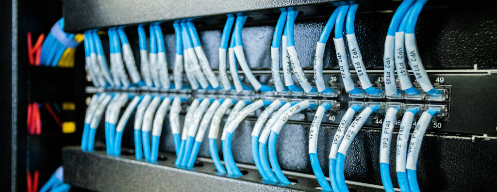
Understand network cabling: Cat6, Cat6A, fiber optics, components, distances, PoE, standards, certification, documentation, and engineering design.
Check it out!
Network cabling is the physical infrastructure used to carry communication signals among equipment, distributors, and network access points. It may use copper or fiber optics and includes not only cables but also terminations, connectors, patch panels, racks, distributors, pathways, spaces, and documentation. In professional environments, this infrastructure must be designed as a system because performance, availability, maintenance, and expansion depend on the combination of architecture, physical media, components, installation, and testing.
The term “network cabling” is broad. It may refer to anything from a simple Ethernet link to a complete structured infrastructure for buildings, industrial facilities, data centers, or campuses. Choosing only “Cat6,” “Cat6A,” or “fiber” is therefore not enough to define a solution. The design must consider applications, distances, PoE, environmental conditions, pathways, racks, interfaces with other disciplines, identification, certification, and lifecycle.
What Makes Up a Network Cabling System?
A professional physical network is formed by elements that work together. The cable is only the transmission medium. Each component’s function must be clear because design failures often arise when attention focuses only on the cable and ignores the rest of the chain.
| Element | Primary function | Risk when poorly specified |
| copper cable | carry electrical signals and, where applicable, PoE | attenuation, crosstalk, heating, distance limitations |
| fiber optic cable | carry optical signals | losses, unsuitable connectivity, transceiver incompatibility |
| connectors and outlets | terminate the link and enable manageable connections | return loss, poor contact, performance degradation |
| patch panel | centralize and manage terminations in the rack | poor traceability and difficult maintenance |
| patch cords | connect administration ports and equipment | excessive length, category mismatch, poor organization |
| racks and cabinets | organize components and equipment | congestion, improper bend radius, limited expansion |
| pathways and spaces | route and protect cables | overfill, deformation, environmental incompatibility |
| identification and documentation | relate the physical installation to the design and as-built | slow troubleshooting and risk of incorrect intervention |
The cabling component architecture should be defined as an architecture rather than a disconnected bill of materials.
Network Cabling vs. Structured Cabling
Network cabling is a functional concept: it exists whenever physical infrastructure interconnects communication devices. Structured cabling is a standardized way of organizing that infrastructure into subsystems, distributors, links, channels, pathways, and spaces with administration and performance criteria.
In a small installation, a few network cables may run directly between devices. In a corporate building, that approach does not scale. Layout changes, user growth, multiple floors, Wi-Fi, CCTV, IP telephony, access control, automation, and redundancy require a manageable architecture.
Structured cabling addresses this by separating functions and creating distribution and administration points. The network can then change without rebuilding the entire physical infrastructure each time.
Structured Cabling Is More Than Visual Organization
A well-organized rack may still be technically inadequate if links exceed limits, pathways are overloaded, identification does not match the as-built, or components are incompatible with the environment.
Structured cabling involves architecture, performance, installation quality, administration, and verifiability. The objective is for another team to understand the network, assess its condition, and expand it without relying on undocumented knowledge.
Main Types of Network Cables
The two main groups used in professional networks are twisted-pair copper cables and fiber-optic cables. The choice depends on distance, application, environment, electrical isolation needs, bandwidth, PoE, cost, interface availability, and expansion strategy.
Twisted-Pair Cables
Twisted-pair cables use copper conductors arranged in pairs. Twisting helps control interference and crosstalk. They are widely used in horizontal cabling because Ethernet and PoE can share the same link and because the connector and equipment ecosystem is mature.
Common categories in current and legacy installations include Cat5e, Cat6, and Cat6A. Higher categories also exist, but their use should be tied to the design and adopted connectivity standard.
O artigo sobre types of network cables explores the differences among categories, fiber, and connectivity.
Cat5e
Cat5e is common in older installed networks and can support 1000BASE-T when the channel and components meet the applicable requirements. In new designs, its use should be evaluated against lifecycle, PoE, density, and application evolution.
The key point is not to confuse the theoretical capability of a category with an automatic design recommendation. New infrastructure should be specified for future demand and replacement cost over its lifecycle.
Cat6
Cat6 is widely used in corporate environments and offers greater performance margin than Cat5e. It supports Gigabit applications and, under specific conditions, 10GBASE-T over reduced distances. Suitability depends on architecture, channel, and application.
O Cat5e vs. Cat6 comparison is useful for existing networks and retrofit decisions.
Cat6A
Cat6A is associated with Class EA and is a natural reference when the design must support 10GBASE-T over channels up to 100 m, provided all other system requirements are met. It is often considered for new projects with longer lifecycles, high-capacity Wi-Fi, multigigabit equipment, dense technical areas, and points that would be difficult to replace later.
A frequent design error is selecting Cat6A without resizing the infrastructure. Larger cable diameter and bend-radius requirements may make conduits, trays, and organizers inadequate. The decision must therefore include pathways and spaces, not only electrical performance.
O artigo Cat6 vs. Cat6A details these sizing considerations.
Shielded vs. Unshielded Cable
Shielding can improve immunity to interference when applied within a coherent system architecture. It should not be treated as an isolated cable feature.
A shielded system requires evaluation of connectors, patch panels, patch cords, shield continuity, equipotential bonding, grounding, and termination practices. Installing shielded cable without controlling these interfaces can add complexity without delivering the expected benefit.
The decision should start from the electromagnetic environment, route, proximity to power circuits, industrial conditions, and application requirements. In severe EMI environments or where electrical isolation is desired, fiber optics may be an alternative.
Fiber Optics in Network Cabling
Fiber optics uses light to carry information and offers important advantages in backbones, building interconnections, data centers, industrial environments, and long-distance networks. It is immune to electromagnetic interference and does not create electrical continuity between endpoints.
The choice between multimode and single-mode depends on distance, interfaces, bandwidth, topology, lifecycle, and project requirements. The design must also define connectors, optical distribution frames, cords, splices, reserves, identification, and testing.
In structured networks, fiber should not be viewed merely as a “faster cable.” It performs specific architectural functions, especially in the backbone. The article Fiber-Optic Backbone explores these decisions in greater depth.
How to Choose the Cabling Type
The choice should relate application, environment, and infrastructure. An initial matrix can guide the study but does not replace engineering design.
| Situation | Solution commonly evaluated | Variables that may change the decision |
| new office network | Cat6 or Cat6A | lifecycle, Wi-Fi, PoE, 10 Gb/s |
| high-capacity Wi-Fi | Cat6A | uplink, power, architecture, and equipment |
| indoor IP CCTV | Cat6/Cat6A according to design | PoE, density, distance, environment |
| environment with significant EMI | shielded cabling or fiber | grounding, pathways, MICE, application |
| backbone between racks | fiber optics | distance, capacity, transceivers, redundancy |
| building interconnection | fiber optics | topology, protection, availability, pathways |
| brownfield retrofit | depends on assessment | existing condition, pathway occupancy, certification, reuse |
This approach avoids two extremes: undersizing the network for short-term savings or oversizing it without demonstrated benefit.
Network Cabling Standards: Why One Reference Is Not Enough
A cabling design should relate each requirement to the standard that actually governs it: architecture, pathways, installation, testing, and equipotential bonding are not the same decision.
Professional projects are rarely governed by a single standard. Topology, pathways, spaces, installation, identification, testing, equipotential bonding, and special environments are covered by different references.
In Brazil, ABNT NBR 14565 is a central reference for cabling architecture in commercial buildings. NBR 16415 addresses pathways and spaces. The NBR 16869 series addresses planning, quality, testing, special configurations, and management. NBR 17040 addresses equipotential bonding of telecommunications infrastructure.
Specific environments have additional references. NBR 16264 relates to residential environments, NBR 16521 to industrial environments, and NBR 16665 to data centers.
Standards Should Govern Decisions, Not Decorate the Specification
Listing standards on the first page of a project does not guarantee compliance. The design should connect each reference to the requirement it actually governs.
| Decision | Brazilian reference associated in the technical base |
| architecture, subsystems, links, and components | NBR 14565 and environment-specific standards |
| pathways, rooms, and pathway infrastructure | NBR 16415 |
| planning, installation, identification, inspection, and acceptance | NBR 16869-1 |
| optical testing | NBR 16869-2 |
| MPTL and special configurations | NBR 16869-3 |
| automated management | NBR 16869-4 |
| passive optical networks | NBR 16869-5 |
| equipotential bonding | NBR 17040 |
The benefit is to turn “comply with standards” into verifiable engineering requirements.
Topology and Subsystems
Topology defines how elements connect physically and influences performance, administration, availability, and expansion. In building structured cabling, the architecture uses distributors and subsystems to organize horizontal distribution and the backbone.
Horizontal cabling connects the work area or device to the corresponding distributor. The backbone interconnects distributors, rooms, and, depending on the project, buildings.
This separation simplifies maintenance and reduces the need for direct cables spanning the entire building. It also allows each segment to be designed according to distance, capacity, and criticality.
Permanent Link, Channel, and MPTL Are Different Configurations
A common error is treating every installed cable as though the test configuration were always the same. Permanent Link represents the fixed portion of the link; Channel includes the cords defined in the configuration; MPTL terminates directly in a modular plug at one end and may be used for fixed devices such as certain cameras and access points when specified by design.
The physical configuration should be defined before installation and reflected in acceptance testing. The article on MPTL provides further application criteria.
Pathways and Spaces Are Part of the Network
Conduits, cable trays, ladder trays, shafts, raised floors, boxes, and technical rooms are not merely civil elements around the cables. They determine capacity, protection, bend radius, separation, maintenance access, and expansion capability.
High-performance cabling installed in inadequate pathways may lose performance margin or become difficult to maintain. Excessive fill increases pulling stress, deformation, and expansion difficulty. Poorly coordinated routes may conflict with electrical, plumbing, HVAC, and structural systems.
NBR 16869-1 recognizes that installation depends on information from other disciplines. Interfaces include electrical distribution and grounding, automation, electronic security, fire systems, HVAC, machinery, plumbing, and equipment for special environments.
For this reason, pathway infrastructure should be coordinated during design.
Environmental Conditions and MICE Classification
Not all cabling operates in office environments. Dust, moisture, chemicals, vibration, mechanical stress, and electromagnetic interference can change component selection and installation methods.
The MICE approach organizes severity related to mechanical conditions, ingress, climatic/chemical conditions, and electromagnetic environment. This analysis influences cables, connectors, shielding, pathway materials, protection, and installation practices.
A classic mistake is specifying Cat6A and assuming the category resolves every requirement. Transmission category and environmental suitability are different criteria. A component may meet electrical performance in the laboratory and still be unsuitable for the actual plant environment.
Power over Ethernet Changes Cabling Sizing
PoE carries data and power over the same link and is widely used for access points, cameras, IP phones, readers, sensors, and other devices. The benefit is significant, but the cable takes on an additional electrical function.
Current flow heats conductors. In bundles, internal cables dissipate heat less effectively. Higher temperature increases resistance and attenuation and may reduce link margins.
Sizing should evaluate:
- device power and PoE classes;
- number of energized pairs;
- conductor gauge and cable construction;
- number of cables per bundle;
- ambient temperature;
- pathway fill and ventilation;
- link length and conditions.
This is particularly important in ceilings, shafts, and technical areas with elevated temperatures. The article Power over Ethernet covers the subject in detail.
Racks, Patch Panels, and Administration
The rack concentrates active equipment, patch panels, organizers, and terminations. Sizing must consider rack units, depth, ventilation, access, bend radius, power, growth, and patch-cord organization.
O patch panel creates an administrable point between fixed cabling and equipment. This separation prevents the horizontal cable from being repeatedly connected and disconnected directly at the switch.
Administration should allow a physical port to be traced to the corresponding outlet or device. This reduces risk during changes and simplifies troubleshooting.
Identification Is Part of the System
NBR 16869-1 provides identification and records for racks, cabinets, cables and ends, patch cords, patch panels, termination points, pathways, spaces, equipotential bonding, buildings, floors, equipment, and interfaces.
Codes should be consistent and durable. Handwritten, duplicated, or undocumented labels compromise maintenance and auditing.
A naming convention can combine building, floor, rack, patch panel, and port to create unique identifiers. The same code should appear on the physical installation, drawings, and certification reports.
Grounding and Equipotential Bonding
Metallic infrastructure elements — racks, cabinets, pathways, shields, and other components — need to be evaluated for continuity and equipotential bonding. This coordination is even more important in shielded systems.
The objective is to control potential differences and integrate telecommunications infrastructure with the project’s equipotential bonding system. The design should be coordinated with electrical systems, lightning protection, and surge protection.
The article on grounding and equipotential bonding in network infrastructure explores these interfaces in greater depth.
Network Cabling Design
Cable selection is a consequence of design. Applications, PoE, backbone, environment, expansion, identification, and acceptance criteria need to be defined before the bill of materials.
The design converts operational needs into technical requirements. It should consider the number of points, supported systems, critical applications, PoE, backbone requirements, density, expected availability, expansion, and documentation level.
A network serving only administrative workstations does not have the same criticality as infrastructure supporting CCTV, access control, automation, high-density Wi-Fi, or a data center.
The Structured Cabling Design should coordinate at least:
- survey and assessment of the existing condition;
- functional and performance requirements;
- architecture and topology;
- number and location of points;
- selection of copper, fiber, and connectivity;
- pathways, spaces, and racks;
- backbone and spare capacity;
- PoE and thermal conditions;
- grounding and interfaces;
- identification and documentation;
- installation criteria;
- testing, certification, and acceptance.
This sequence reduces improvised field decisions.
Installation: A Good Design Can Be Lost During Construction
Even a good design can result in a poor network if installation practices violate mechanical or electrical requirements. Excessive pulling tension, crushing, overtightened ties, tight bend radii, excessive untwisting, poor terminations, and improvised routes affect performance and durability.
Construction must also preserve separation, identification, and spare capacity. It is common to find networks where the first installation was correct but later expansions progressively degraded organization.
Quality control should occur during installation. Waiting until final certification to discover all problems concentrates rework at closeout and makes root causes harder to identify.
Cabling Certification and Acceptance
Network certification verifies whether the installed link meets the performance limits associated with the defined configuration. It does not measure “Internet speed” and should not be confused with a simple continuity test.
For copper, parameters may include wire map, length, insertion loss, NEXT, PSNEXT, return loss, ACR, delay, and other measurements required by the selected limit. The test configuration should represent the accepted object: Permanent Link, Channel, MPTL, or another defined configuration.
The article How to Certify a Structured Cabling Network presents the field procedure in detail.
A Standalone PASS Is Not Acceptance Documentation
A summary showing only “PASS” loses much of its technical value. The report should allow traceability of link identification, standard and limit, test configuration, category/class, instrument, adapters, calibration, date, operator, and parameter results.
Native tester files are also important because they preserve structured data and metadata that may be lost in summary PDFs. During an audit, they help verify that the report corresponds to the original test.
A robust package may include native files, PDFs, a master link matrix, retest map, calibration records, instrument list, and correction records.
Documentation and As-Built
The installed infrastructure needs to be converted into operational documentation. The original design shows intent; the as-built should reflect what was actually constructed.
Changes in routes, ports, racks, terminations, and equipment must be incorporated. The Engineering As-Built should remain consistent with identifiers and test results.
Without this, the network begins to lose traceability immediately after handover. Years later, an organization may have physically sound cabling but little confidence in routes, destinations, or available capacity.
Network Cabling in Existing Environments
Brownfield projects require a different approach. Before specifying new materials, the existing infrastructure should be mapped and active, abandoned, and reusable assets distinguished.
An inspection may evaluate:
- categories and condition of existing cables;
- pathway occupancy;
- condition of racks and patch panels;
- identification and documentation;
- termination quality;
- backbone capacity;
- grounding and equipotential bonding;
- previous certification results;
- unused points and abandoned cables;
- ability to expand without critical interruption.
Um existing-conditions survey reduces the risk of designing from outdated drawings.
Common Errors in Network Cabling Design
Some errors recur because they appear minor but affect the entire system.
Choosing the Category Before Understanding the Application
The decision should start from bandwidth, distance, PoE, environment, lifecycle, and replacement-cost requirements. Starting with “we will use Cat6A” reverses the process.
Ignoring Pathways and Spaces
A higher-category cable does not compensate for an overloaded conduit, incorrect bend radius, or inaccessible route. Physical infrastructure is part of performance and maintainability.
Treating RJ45 as a Category
RJ45 is a widely used connectivity term, but it does not define Cat5e, Cat6, or Cat6A. Category must be specified for the cable, connectors, and corresponding channel.
Installing Shielding Without an Equipotential-Bonding Strategy
Shielding must be coordinated with connectivity, continuity, grounding, and environment. Otherwise, it may add cost and complexity without controlled benefit.
Sizing Only by Number of Users
Cameras, access points, readers, sensors, and automation use network points and PoE regardless of desk count. Infrastructure should consider all digital systems in the project.
Leaving Documentation Until the End
Identification and as-built documentation should accompany implementation. Reconstructing information after construction increases errors and loses change traceability.
Checklist for Evaluating a Cabling Solution
Before procuring or accepting a network, verify whether the following questions have objective answers:
- what architecture and topology have been defined?
- which applications and speeds must be supported?
- which systems will use PoE?
- which class/category and link configuration were specified?
- where will copper be used and where will fiber be used?
- do pathways support current fill and future expansion?
- do racks have adequate space, depth, organization, power, and ventilation?
- does the environment require additional protection, shielding, or fiber?
- is there a grounding and equipotential-bonding strategy?
- is identification unique and consistent with the drawings?
- which tests will be performed?
- are the instrument and calibration compatible with the test?
- are native files and PDFs included in the handover?
- will the as-built be updated with field changes?
- is there measurable spare capacity for expansion?
Generic answers to these questions indicate that the specification is still immature.
Final Considerations
Network cabling is an engineering infrastructure, not merely a collection of cables. Final performance depends on the interaction among physical media, connectors, topology, pathways, racks, environment, PoE, equipotential bonding, identification, documentation, and testing.
In professional designs, the choice among Cat6, Cat6A, shielding, or fiber follows from the requirements. The objective is not to install the most expensive technology, but to build a verifiable, manageable infrastructure suited to the project lifecycle.
When architecture, installation, and acceptance are treated as an integrated process, cabling becomes a stable physical foundation for equipment, applications, and future expansion.
In existing networks, the decision to reuse, replace, or expand should start from a technical assessment of installed conditions and the actual capacity of pathways, racks, and links.
Technical References
[1] BRAZILIAN ASSOCIATION OF TECHNICAL STANDARDS. ABNT NBR 14565: Structured cabling for commercial buildings. Rio de Janeiro: ABNT. Available at: https://www.abntcatalogo.com.br/
[2] BRAZILIAN ASSOCIATION OF TECHNICAL STANDARDS. ABNT NBR 16415: Pathways and spaces for structured cabling. Rio de Janeiro: ABNT. Available at: https://www.abntcatalogo.com.br/
[3] BRAZILIAN ASSOCIATION OF TECHNICAL STANDARDS. ABNT NBR 16869: Structured cabling — Series. Rio de Janeiro: ABNT. Available at: https://www.abntcatalogo.com.br/
[4] BRAZILIAN ASSOCIATION OF TECHNICAL STANDARDS. ABNT NBR 17040: Equipotential bonding of telecommunications infrastructure. Rio de Janeiro: ABNT. Available at: https://www.abntcatalogo.com.br/
[5] INTERNATIONAL ORGANIZATION FOR STANDARDIZATION; INTERNATIONAL ELECTROTECHNICAL COMMISSION. ISO/IEC 11801: Information technology — Generic cabling for customer premises. Available at: https://www.iso.org/
Frequently Asked Questions
It is the physical infrastructure that carries signals between network equipment and points, including cables, fiber, connectors, patch panels, racks, pathways, and documentation.
Network cabling is the broad concept of physical network infrastructure. Structured cabling organizes that infrastructure into a standardized architecture with subsystems, distributors, links, and administration criteria.
The choice depends on applications, lifecycle, 10 Gb/s requirements, PoE, Wi-Fi, environment, pathways, and future replacement cost. Cat6A should not be selected in isolation.
Fiber is commonly used for backbones, longer distances, building interconnections, severe EMI environments, and applications requiring capacity or electrical isolation.
Yes. Electrical current heats conductors, especially in bundles, requiring evaluation of power, conductor gauge, temperature, pathway fill, and ventilation.
Because they determine protection, capacity, bend radius, administration, maintenance access, and expansion capability.
When required by the design or contract, certification should demonstrate that links meet the defined limits. In a robust handover, results are associated with identification and the as-built.
Depending on scope, deliverables may include identification, as-built drawings, a link matrix, test reports, native tester files, calibration records, and component documentation.
Complementary Technical Materials
Related Solutions
- Structured Cabling: design, implementation, certification, and management
- Connectivity and Logical Network
Related Services
- Structured Cabling Design
- Fiber-Optic and Optical-Network Design
- Engineering Testing and Technical Tests
