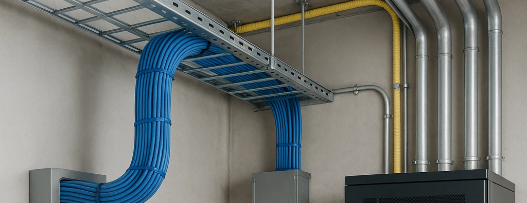
Understand dry infrastructure for structured cabling: conduits, cable trays, ladder trays, shafts, 40% fill, NBR 16415, design, inspection, and acceptance.
Check it out!
Dry infrastructure is the set of physical pathways, spaces, and supports prepared to receive cabling and systems independently of active equipment installation. In structured cabling, it includes conduits, cable trays, ladder trays, raceways, J-hooks, shafts, pull boxes, raised floors, telecommunications rooms, equipment rooms, and entrance infrastructure.
Dry-infrastructure design should not be treated simply as defining “where the cable runs.” ABNT NBR 16415 requires pathways and spaces to protect cabling throughout its lifecycle and to consider cable quantity and dimensions, bend radii, future expansion, accessibility, grounding of metallic elements, environmental conditions, and interfaces with other installations. An undersized or inaccessible route can make installation unfeasible even when the logical network design is correct.
What Dry Infrastructure Is and What It Includes
In networking and telecommunications, dry infrastructure is the passive physical layer that prepares the building to receive cables. It is not the structured cabling itself, but the building infrastructure that enables that cabling to be installed, maintained, replaced, and expanded.
| Element | Main function | Critical design point |
| Conduit | Protection and routing in enclosed sections | fill, bends, boxes, and pulling |
| Cable tray | Accessible distribution for larger cable volumes | load, width, fill, and support |
| Ladder tray | Open support for large volumes | bend radius, load, and accessibility |
| Raceway | Surface/perimeter distribution | segregation and capacity |
| J-hook | Noncontinuous support for small quantities | spacing, sag, and access |
| Shaft/riser | Vertical distribution | reserve, accessibility, and segregation |
| Pull box | Assistance with cable pulling | cannot be used for splices |
| Raised floor | Flexible underfloor distribution | clear height, accessibility, and clashes |
| Telecommunications room | Floor distribution | location, power, cooling, and maintenance |
| Equipment room | Main equipment and distributors | area, access, load, power, and cooling |
Dry infrastructure may support horizontal cabling, building backbone, and campus backbone. Selection criteria vary according to subsystem, environment, and cable type.
Dry Infrastructure vs. Structured Cabling
Structured cabling is the system of cables, connecting hardware, and cords capable of supporting telecommunications applications. Dry infrastructure is the set of pathways and spaces that physically enables that system.
This distinction is important in design and contracting. Construction may deliver cable trays and conduits without installing cables; likewise, a network design may define outlets and racks without detailing sufficient pathways. When the two disciplines are not coordinated, problems appear during execution: saturated conduits, poorly positioned boxes, insufficient shafts, inability to respect bend radii, or routes conflicting with electrical, HVAC, plumbing, and architectural systems.
NBR 16415 and Requirements for Pathways and Spaces
ABNT NBR 16415:2021 is the main Brazilian reference for pathways and spaces intended for structured cabling. It establishes requirements for indoor, outdoor, underground, and aerial environments, as well as rooms, racks, boxes, and support structures.
General principles include:
- mechanical protection of cabling;
- installation in dry locations not subject to flooding;
- prohibition on using elevator shafts and stairwells as pathways;
- dedicated pathways for structured cabling, without using the same distribution infrastructure as electrical cables;
- smooth internal surfaces without burrs or sharp edges;
- absence of pressure points capable of deforming or degrading cables;
- grounding and equipotential bonding of metallic infrastructure;
- explicit consideration of future expansion;
- access for installation, maintenance, inspection, and replacement.
The standard also treats telecommunications spaces as part of the infrastructure: pathway quality loses value if the rack or technical room does not provide adequate access, ventilation, power, and organization.
How to Choose between Conduit, Cable Tray, Ladder Tray, and J-Hooks
There is no single ideal pathway for every installation. The decision should consider density, accessibility, environment, expansion needs, cable type, and construction clashes.
| Situation | Frequently suitable solution | Note |
| Embedded/enclosed section | conduit | requires fill and pulling calculations |
| Technical corridor with many cables | cable tray | facilitates maintenance and expansion |
| Large volume or larger-diameter cables | ladder tray | high accessibility and open support |
| Office retrofit | raceway | reduces civil intervention |
| Removable ceiling with few cables | J-hooks | only where permanent access exists |
| Vertical distribution | shaft + ladder trays/cable trays | requires floor-by-floor coordination |
| Technical room/data center | ladder trays/cable trays/raised floor | consider density, airflow, and segregation |
The diagram is only a starting point. Mechanical strength, environmental exposure, fire behavior, grounding, segregation, and manufacturer requirements remain part of the specification.
Conduit Sizing: 40% Fill
NBR 16415 establishes that conduits intended for structured cabling should be sized for a maximum design fill of 40% of the internal cross-sectional area. This prevents sizing from being based on approximate diameter sums or the visual impression that “one more cable still fits.”
The calculation should use the actual cable diameter specified by the manufacturer. Cat6A, shielded cables, optical cables, and special cables may have significantly different diameters, changing pathway capacity.
Annex B of the standard provides calculation examples, but the final quantity should be determined using the actual project dimensions. Fill ratio also does not eliminate the need to verify bend radius and pulling force: a conduit may have available area and still be impossible to pull through because of excessive bends.
Bends, Boxes, and Pulling Distances in Conduits
Cable pulling needs to be considered during design. NBR 16415 requires the route to be as direct as possible and limits geometry between boxes.
- no individual bend may exceed 90°;
- there may be no more than two 90° bends between pull boxes;
- the sum of bends between boxes may not exceed 180°;
- 180° U-bends are not permitted as a routing solution;
- the internal bend radius should be at least six times the conduit internal diameter, associated with the permitted fill;
- boxes should allow pulling without turning the passage into a new bottleneck.
The standard also distinguishes straight sections and sections with bends when positioning boxes. The designer should evaluate actual length, cable pulling force, and pulling method rather than simply repeating a standard distance on all routes.
A Pull Box Is Not a Splice Box
A pull box exists to assist routing and pulling. It cannot be used for cable splices. When the design includes a splice, an appropriate and accessible splice box or space should be provided.
Another recurring error is using the box itself as the pathway bend. NBR 16415 provides for boxes in straight sections; direction changes should allow the cable to maintain its bend radius and be handled without deformation.
Flexible Conduit: Exception, Not the Standard Solution
NBR 16415 recommends flexible conduit only when it is the only practical alternative. When used, the standard recommends adopting one commercial size larger than would be used for rigid conduit while maintaining the same cable quantity.
This is because internal geometry and flexibility increase pulling difficulty. In detailed design, flexible sections should be short, accessible, and justified, rather than used as a way to resolve clashes that should have been coordinated.
Cable Trays and Ladder Trays: Capacity Is Not Just Area
For cable trays and ladder trays, sizing needs to consider usable width, stacking height, cable load, support, bend radius, accessibility, and reserve. Filling the structure to its physical limit reduces expansion capacity and makes intervention difficult.
On routes with multiple technologies — copper, fiber, remote power, and special-system cables — organization should avoid compression, unnecessary crossings, and overlap that prevents access to lower layers.
The specification should indicate at least:
- dimensions and material;
- finish and corrosion protection;
- bend, branch, and reducer accessories;
- fastening method and support spacing;
- design load;
- electrical continuity and equipotential bonding when metallic;
- covers when required by the environment;
- reserve for expansion;
- treatment of fire-rated penetrations.
J-Hooks: Where They Can and Cannot Be Used
J-hooks are noncontinuous supports permitted for horizontal distribution and backbone under appropriate conditions. They should not be used in permanently enclosed and inaccessible locations.
NBR 16415 establishes, among other criteria:
- attachment directly to the building structure or to dedicated raised-floor elements;
- removable ceiling tiles when installed above an enclosed ceiling;
- support spacing between 1.2 m and 1.5 m on straight sections;
- maximum sag at the midpoint between supports of 0.30 m;
- bends and branches built while respecting minimum cable bend radii;
- clearance allowing ceiling tiles to be removed without damaging cabling.
Tying cables directly to piping, sprinklers, lighting structures, or installations from other disciplines is not equivalent to a designed pathway.
Shafts and Risers
A shaft is the vertical space used to connect floors and telecommunications rooms. Its design needs to provide more than a geometric opening: support systems, access, reserve capacity, slab penetrations, fire compartmentation, and interfaces with electrical and building systems need to be defined.
In buildings with predictable growth, the shaft should allow cables to be added without dismantling existing systems. When telecommunications and other services occupy the same building zone, coordination needs to preserve dedicated pathways and the separations required by applicable standards.
Telecommunications Rooms and Equipment Rooms
Dry infrastructure also includes spaces. NBR 16415 requires telecommunications and equipment rooms to be dedicated to telecommunications functions and to consider access, power, ventilation/cooling, lighting, floor loading, environmental protection, and expansion.
For racks and cabinets, the standard establishes a minimum clearance of 0.90 m on faces requiring access, with 1.20 m recommended. Routes should allow equipment and cables to be brought in and removed without improper dismantling of the installation.
Poorly located rooms create long horizontal routes and complicate maintenance. Location should be coordinated with the served area, shafts, and architecture from the preliminary design stage.
How to Size Project Dry Infrastructure
When pathways, shafts, and technical rooms are defined only during construction, cabling ends up adapting to leftover space. Structured Cabling Design sizes routes, fill, racks, reserves, and acceptance criteria before execution.
Sizing can be structured in a verifiable sequence:
- survey the number of outlets, cables, and technologies;
- separate horizontal cabling, building backbone, campus backbone, and carrier entrances;
- obtain actual cable diameters, masses, bend radii, and allowable pulling tension;
- establish preliminary routes and technical rooms;
- calculate conduit fill and cable-tray/ladder-tray capacity;
- provide reserve capacity for growth and new technologies;
- coordinate with electrical, plumbing, HVAC, fire protection, architecture, and structure;
- define supports, boxes, penetrations, and firestopping;
- verify grounding/equipotential bonding of metallic elements;
- document inspection and acceptance criteria.
A calculation record should allow another professional to reproduce the sizing. Specifying only “1 in. conduit” or “100 × 50 cable tray” without relating cable quantity and dimensions does not demonstrate adequacy.
Technical Reserve and Future Expansion
Expansion should not be treated merely as “leftover space.” It needs to exist in the segments that actually limit the system: shafts, penetrations, buried ducts, building entrances, trays, boxes, and technical rooms.
For furniture pathways, NBR 16415 uses 40% design fill and 60% maximum capacity for expansion. For underground pathways, the standard recommends considering additional or empty ducts where future excavation would be difficult and expensive.
The best places to invest in reserve capacity are those where future expansion would require greater civil intervention or downtime.
Underground Infrastructure and Campus Backbone
Underground routes need to consider drainage, traffic, topography, access, pulling forces, manholes, boxes, and future expansion. For campus environments, NBR 16415 discourages direct-buried cable as the preferred solution because future replacements and expansions become more difficult.
Manholes should keep cables off the base, provide maintenance space, and respect bend radii. The design should distinguish manholes, pull boxes, and splice boxes.
Aerial Pathways
Aerial installations require analysis of spans, sag, wind, temperature, anchoring, trees, safety, and separation from electrical networks. The pathway should allow maintenance without compromising the support structure.
On campuses or industrial plants, the choice between underground and aerial routes should consider not only CAPEX but also availability, damage risk, ease of expansion, and environmental exposure.
Multidisciplinary Coordination: Where Dry Infrastructure Commonly Fails
Clashes with electrical, HVAC, plumbing, fire-protection, and architectural systems need to be resolved during design. Telecommunications Design coordinates physical pathways with network requirements and other systems to reduce field deviations and rework.
Most clashes appear when telecommunications is detailed after architecture, electrical, and building services. The result is often route deviations during construction, interrupted cable trays, occupied shafts, hidden boxes, or routing close to interference sources.
A coordination review should check:
| Interface | Typical risk | Design decision |
| Electrical | shared pathways/interference | segregation, barriers, and routes |
| HVAC | ducts blocking cable trays | routing elevations and levels |
| Plumbing | piping over racks/rooms | repositioning and protection |
| Fire protection | penetrations without sealing | specified firestop system |
| Structure | lack of fastening points | supports and inserts |
| Architecture | small rooms/inadequate access | sizing and doors |
| Electronic security | points added late | reserve capacity and coordinated shared pathways |
Dry infrastructure should be frozen at a level appropriate to the design stage before execution, and field changes need to be recorded.
Separation between Telecommunications and Power
NBR 16415 establishes that structured cabling should not use the same distribution infrastructure as electrical cables. Physical separation and the use of barriers should be coordinated with electrical standards and installation characteristics.
There is no single universal distance applicable to every circuit and pathway. Power level, conductor arrangement, pathway material, shielding, parallel-run length, and environment influence the applicable criteria. Distance tables should therefore be used within the correct standards context rather than as an isolated rule.
Grounding and Equipotential Bonding of Metallic Pathways
All metallic infrastructure, components, and supports should be grounded and equipotentially bonded according to the applicable architecture. This includes attention to joints between sections, supports, racks, and interfaces with the electrical installation.
Continuity should not be assumed merely because two metallic parts touch. Paint, oxidation, bolts, and accessories can alter behavior. The dedicated article on grounding and equipotential bonding in network infrastructure examines NBR 17040, bonding bars, racks, and shielding in greater depth.
Dry Infrastructure for PoE and High Density
PoE does not change the basic function of the pathway, but it increases the importance of density, temperature, and bundle organization. Large groups of remotely powered cables can raise temperature and affect insertion loss and channel capacity.
The design should avoid unnecessary compaction, consider environmental thermal characteristics, and allow cable reorganization. In Wi-Fi, IP video surveillance, access control, and automation, convergence of many devices in the same ceiling space may require increased pathway capacity even before the number of users grows.
How to Specify Dry Infrastructure in Design and Procurement
A verifiable specification should avoid generic descriptions such as “provide required infrastructure.” The document should indicate types, dimensions, materials, finish, accessories, supports, load, fill criteria, grounding, environmental protection, and installation requirements.
For technical bid equalization, it is useful to require a matrix confirming:
- manufacturer and product line of pathways/accessories;
- material and thickness where applicable;
- usable dimensions;
- load capacity;
- finish and environmental resistance;
- all bend, branch, and fastening accessories;
- continuity/equipotential-bonding method;
- compatibility with firestop systems;
- technical documentation and traceability.
Substitutions during construction should be evaluated based on performance and actual dimensions, not only on an equivalent commercial description.
Inspection before Cable Pulling
Dry infrastructure should be released before cables are installed. A readiness inspection reduces the risk of discovering during pulling that the route is incomplete or that the material will be damaged.
The checklist may include:
- physical continuity of routes;
- internal cleanliness and absence of burrs;
- accessible and correctly positioned boxes;
- compatible bends and radii;
- complete supports attached to the appropriate structure;
- available fill according to design;
- released shafts and penetrations;
- protection against water and contaminants;
- segregation from other systems;
- equipotential bonding of metallic parts;
- specified firestop seals;
- pathway identification.
Acceptance and As-Built Documentation
Acceptance should not end with a generic visual inspection. The As-Built needs to show routes, dimensions, boxes, rooms, shafts, penetrations, and major reserves. Field changes should be incorporated into the final documentation set.
An acceptance matrix may relate each pathway to design, inspection, pending items, and release for cable pulling. On large projects, georeferenced photographs or photos associated with each area facilitate future maintenance.
| Evidence | Why it matters |
| As-Built plans and sections | locate routes and clashes |
| Calculation record | demonstrates capacity and fill |
| Datasheets | confirm dimensions/load/material |
| Photos of shafts and concealed sections | record condition before closure |
| Inspection checklist | demonstrates readiness before cabling |
| Equipotential-bonding records | demonstrate continuity of metallic infrastructure |
| Pending-item list | prevents acceptance with open nonconformities |
Common Errors in Dry Infrastructure
- sizing by nominal cable quantity without using actual diameter;
- filling conduits above the design criterion;
- using too many bends between boxes;
- using a pull box for splices;
- hiding boxes above fixed ceilings;
- supporting cables on piping and installations from other disciplines;
- designing a shaft without reserve capacity or access;
- leaving cable trays discontinuous at penetrations;
- providing a rack without front/rear maintenance space;
- mixing power and telecommunications in the same pathway without the applicable architecture;
- omitting grounding/equipotential bonding of metallic pathways;
- pulling cables before infrastructure inspection;
- changing routes in the field without updating the As-Built.
Final Considerations
Dry infrastructure is an engineering discipline that connects architecture, structure, electrical systems, telecommunications, and execution. Cabling quality depends directly on pathways and spaces that allow installation without deformation, accessible maintenance, and planned expansion.
NBR 16415 turns this need into verifiable criteria: dedicated pathways, mechanical protection, fill, bends, boxes, technical rooms, accessibility, grounding, and growth planning. When dry infrastructure is sized before construction and coordinated with other disciplines, rework, field changes, and future downtime are reduced.
Installed infrastructure should not be released merely because it is physically assembled. During commissioning, routes, accessibility, documentation, pending items, and interfaces are verified before technical acceptance and final delivery.
Technical References
[1] BRAZILIAN ASSOCIATION OF TECHNICAL STANDARDS. ABNT NBR 16415:2021 — Pathways and spaces for structured cabling. Rio de Janeiro: ABNT, 2021. Available at: https://www.abntcatalogo.com.br/
[2] BRAZILIAN ASSOCIATION OF TECHNICAL STANDARDS. ABNT NBR 14565 — Structured cabling for commercial buildings. Rio de Janeiro: ABNT. Available at: https://www.abntcatalogo.com.br/
[3] BRAZILIAN ASSOCIATION OF TECHNICAL STANDARDS. ABNT NBR 16869-1 — Structured cabling — Part 1: planning requirements. Rio de Janeiro: ABNT. Available at: https://www.abntcatalogo.com.br/
[4] ISO/IEC. ISO/IEC 11801-1 — Information technology — Generic cabling for customer premises — General requirements. Available at: https://www.iso.org/standard/66182.html
[5] TIA. ANSI/TIA-569 — Telecommunications Pathways and Spaces. Available at: https://tiaonline.org/standards/
Frequently Asked Questions
It is the set of physical pathways, spaces, and supports prepared to receive cables and systems, such as conduits, cable trays, ladder trays, shafts, boxes, and technical rooms.
ABNT NBR 16415 establishes a maximum design fill of 40% of the conduit’s internal cross-sectional area, using actual cable dimensions.
No. A pull box assists cable pulling. Splices should use an appropriate splice box or space.
A conduit may not have an individual bend greater than 90°, more than two 90° bends between boxes, or a sum of bends greater than 180°.
NBR 16415 establishes spacing between 1.2 m and 1.5 m on straight sections, with maximum sag of 0.30 m at the midpoint.
Yes. Pathways and spaces are part of the system. Telecommunications rooms, equipment rooms, entrances, and racks should be sized for access, power, cooling, maintenance, and expansion.
No. Structured cabling should use dedicated pathways and may not use the same distribution infrastructure as electrical cables.
The route should be complete, clean, accessible, supported, with correct boxes and bends, available capacity, segregation, environmental protection, equipotential bonding, and completed penetrations.
Complementary Technical Materials
Related Services
Related Solutions
Main Content on the Topic
- Complete Guide to Structured Cabling
- Horizontal-Cabling Pathways and Infrastructure
- NBR 14565
- Structured Cabling Standards
