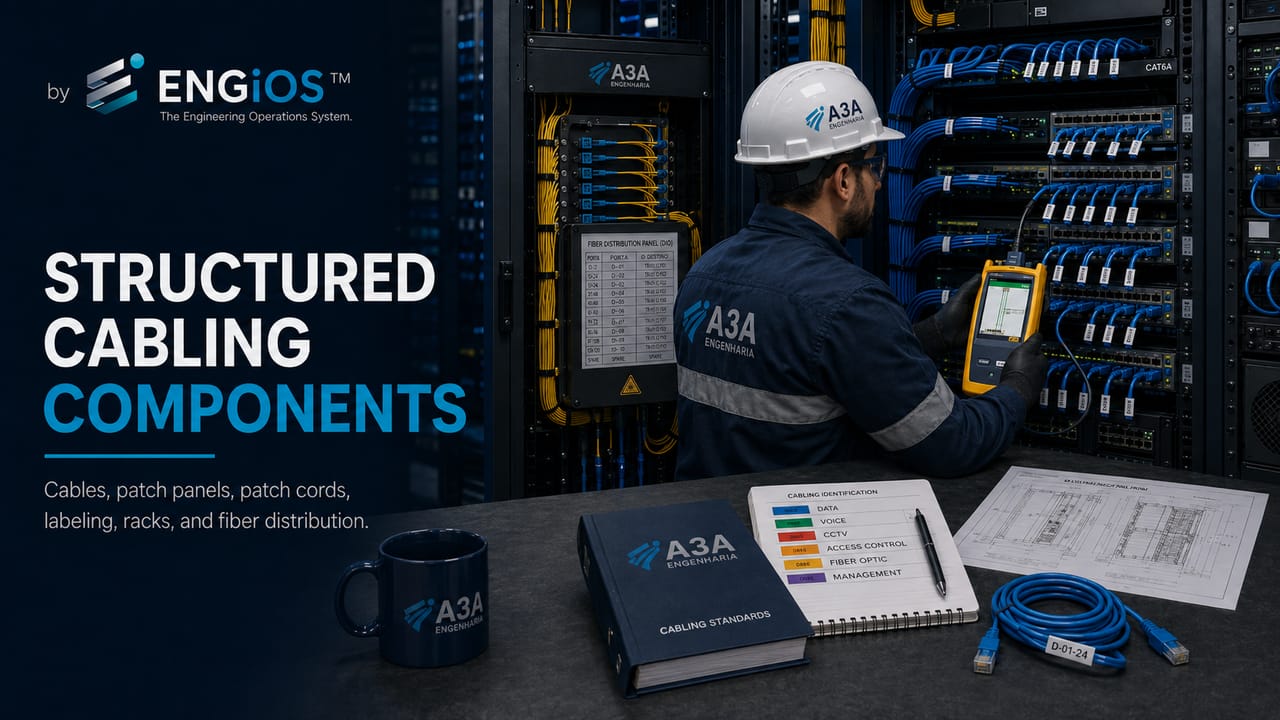
Learn about the main structured cabling components: copper cables, fiber optics, patch panels, racks, DIOs, patch cords, outlets, connectors, pathways, identification, and certification.
Check it out!
Structured cabling components form the physical system responsible for organizing, connecting, identifying, protecting, and certifying a building’s telecommunications infrastructure. The main components include copper cables, fiber optics, patch panels, DIOs, racks, patch cords, RJ45 outlets, keystones, cable managers, cable trays, conduits, identification, and technical documentation.
In a professional network, these items should not be treated as isolated purchasing components. Final performance depends on compatibility among all components, proper installation, link certification, rack organization, and compliance with structured-cabling technical standards.
This article works as a technical map of the system’s main components and indicates when each topic should be explored in greater depth through specific content in A3A Engenharia’s structured-cabling cluster.
What Are the Main Structured Cabling Components?
The main structured cabling components are:
| Component | Main function | Where it appears in the system |
| Copper cables | Transmit data over twisted-pair links | Horizontal cabling, network outlets, IP CFTV, Wi-Fi, and IP telephony |
| Fiber optics | Interconnect racks, buildings, backbones, and longer-distance links | Backbone, data centers, campuses, industrial environments, and optical networks |
| Patch panel | Terminate and organize copper cables in the rack | Technical room, telecommunications rack, and horizontal distribution |
| DIO | Terminate and organize optical fibers | Optical backbone, racks, splices, and optical patch cords |
| Rack or cabinet | Concentrate patch panels, switches, DIOs, and cable managers | Technical rooms, DPCs, data centers, and distributors |
| Patch cords | Provide connections between patch panels, switches, DIOs, and equipment | Rack front, work areas, and optical connections |
| Outlets and keystones | Terminate cables at work areas | Telecommunications outlets, desks, rooms, cameras, and access points |
| Pathways and spaces | Provide routes and spaces for cable installation | Cable trays, conduits, shafts, ladder racks, boxes, and technical rooms |
| Identification | Provide traceability for outlets, ports, and cables | Labels, maps, drawings, reports, and as-built documentation |
| Certification | Demonstrate link performance | Testing, reports, technical acceptance, and final documentation |
To understand how these components are organized within the network’s physical architecture, see the article on Structured Cabling Subsystems.
Use this article as a map of the cabling cluster.
After identifying the main components, deepen your view of the complete system: subsystems, standards, design, installation, certification, racks, and technical documentation.
Copper Twisted-Pair Cables
Copper twisted-pair cables are the most commonly used cables for Ethernet network outlets. The most common categories in current installations are Cat5e, Cat6, and Cat6A.
The cable category affects transmission capacity, frequency, distance, application, and certification requirements. However, channel category does not depend only on the cable. It also depends on connectors, patch panels, patch cords, outlets, installation method, and final testing.
For more detail, see Types of Network Cables, UTP Cable, and Cat6 vs. Cat6A.
Fiber Optics and Backbone
Fiber optics are used when greater distance, higher capacity, electromagnetic immunity, or interconnection among racks, buildings, floors, technical rooms, and data centers is required.
In structured cabling, fiber commonly appears in backbones, campus interconnections, industrial environments, DPCs, data centers, and higher-capacity connections. The choice between multimode and single-mode fiber depends on distance, active equipment, transceivers, topology, and expansion strategy.
In optical networks, the system includes optical cables, DIOs, adapters, connectors, optical patch cords, splice trays, identification, and optical-loss testing. See also DIO in Optical Networks and Fiber-Optic Backbone.
Patch Panel
A patch panel is the connection panel installed in the rack to terminate and organize permanent twisted-pair cables. It allows network outlets to be connected to switches through patch cords without directly handling the horizontal cabling.
The patch-panel category must be compatible with the system category, such as Cat5e, Cat6, or Cat6A. Using a patch panel rated below the specified cable category can limit channel performance and compromise certification.
The patch panel is also essential for identification, maintenance, moves and changes, and rack documentation. For more detail, see Patch Panel: What It Is and What It Does.
Telecommunications Racks and Cabinets
Racks and cabinets concentrate patch panels, DIOs, switches, routers, firewalls, UPS systems, power strips, cable managers, and telecommunications equipment.
Rack organization affects maintenance, ventilation, expansion, identification, and operational safety. A disorganized rack makes troubleshooting more difficult, increases the risk of accidental disconnections, and impairs network traceability.
In professional designs, the rack should include space for active equipment, horizontal and vertical cable managers, technical reserve, power distribution, ventilation, grounding, and documentation. See also Network Rack: Organization, Components, and Best Practices.
Patch Cords
Patch cords are flexible cables used to connect patch-panel ports to switches, outlets to equipment, and DIOs to optical equipment.
They may look simple, but they directly affect channel performance. Patch cords of a lower category, improper length, poor provenance, or damaged connectors can compromise the network even when the permanent cabling has been properly installed.
In professional racks, patch cords should have appropriate length, a color standard where useful, consistent organization, and identification compatible with the port map.
RJ45 Outlets, Connectors, and Keystones
RJ45 outlets and keystones terminate cables in work areas, rooms, cameras, access points, controllers, and other telecommunications points.
Correct termination preserves the electrical performance of the link. Excessive untwisting, poor termination, incompatible category, or low-quality components can cause performance loss and certification failures.
Keystones, outlets, and connectors must be compatible with the cable category and the application specified in the design.
DIO and Optical Components
The DIO, or Internal Optical Distributor, organizes and protects optical fibers in the rack. It houses adapters, connectors, splice trays, optical patch cords, and link identification.
In fiber networks, the DIO performs a role similar to a copper patch panel, adapted to the characteristics of fiber optics. It prevents improper fiber handling, protects splices, and facilitates maintenance.
Fiber installation requires attention to bend radius, connector cleanliness, identification, polarity, optical loss, and testing. In designs with an optical backbone, the DIO should be included in both the design and the as-built documentation.
Cable Managers
Horizontal and vertical cable managers help route patch cords and cables within the rack. They reduce crossings, preserve bend radius, prevent mechanical stress on ports, and facilitate maintenance.
Organization is not merely aesthetic. It affects operations, support time, traceability, and future expansion. In environments with many outlets, PoE switches, IP CFTV, and enterprise Wi-Fi, appropriate cable managers are essential.
Pathways and Spaces
Pathways and spaces comprise the routes and spaces used to route, protect, and organize cables. They include cable trays, conduits, ladder racks, shafts, pull boxes, technical rooms, ducts, supports, and infrastructure reserve capacity.
Without adequate pathways, even good components can be installed improperly. The infrastructure must consider fill, bend radius, segregation between power and data, accessibility, expansion, and coordination with architecture, electrical systems, lightning protection, CFTV, access control, and automation.
For more detail, see Pathways and Spaces for Structured Cabling.
Horizontal Cabling, Backbone, and Subsystems
Structured cabling components are organized within subsystems. Horizontal cabling connects the work area to the floor distributor or rack. The backbone interconnects racks, technical rooms, floors, buildings, or higher-concentration areas.
Separating subsystems helps standardize design, installation, certification, and maintenance. It also prevents decisions from being made ad hoc at each network point.
See also Horizontal Cabling and Structured Cabling Subsystems.
Identification and Documentation
Identification is an essential part of the system. Each outlet should be traceable across the outlet, cable, patch panel, switch port, rack, technical room, drawing, certification report, and final documentation.
Documentation may include drawings, rack diagrams, port maps, outlet schedules, cable identification, certification reports, quantities, design reports, and as-built documentation.
In larger environments, inventory, IPAM, and DCIM tools such as NetBox can help keep the infrastructure traceable and auditable.
Grounding, Equipotential Bonding, and Surge Protection
Metallic components, racks, cable trays, shields, DIOs, infrastructure, and equipment must be evaluated with respect to equipotential bonding and grounding.
This is especially important in networks with shielded cabling, IP CFTV, automation, industrial environments, lightning protection systems, surge protective devices, and sections exposed to electrical surges. Inadequate grounding can compromise safety, availability, and performance.
See also Grounding and Equipotential Bonding in Network Infrastructure and SPD for Data Lines, CFTV, Automation, and Telecommunications.
Incompatible components create failures that are difficult to correct after installation.
Cables, patch panels, DIOs, racks, pathways, identification, and certification criteria need to be defined in the design before implementation is contracted.
Certification of Components and the Channel
Certification demonstrates whether the installed link meets the specified category. In copper cabling, it is not enough for the cable to be Cat6 or Cat6A: the complete system must meet the category parameters.
Certification evaluates link or channel performance considering the cable, connectors, patch panels, outlets, patch cords, and installation. In fiber optics, testing may involve optical loss, connector inspection, polarity, and OTDR, depending on the scope.
For technical-acceptance criteria, see Cable Certification Parameters and Network Cabling Certification.
Are Active Devices Part of Structured Cabling?
Switches, routers, firewalls, controllers, and servers are not passive structured-cabling components in the same way as cables, patch panels, and outlets. However, they connect directly to the physical infrastructure and influence network architecture.
Therefore, the physical design must consider active equipment, available ports, PoE, uplinks, redundancy, VLANs, addressing, security, and expansion. The boundary between the physical network and the logical network must be clear in the documentation.
Common Mistakes When Selecting Components
The most common mistakes include:
- purchasing components separately without a design;
- mixing different categories in the same channel;
- using a higher-category cable with a lower-category patch panel or connector;
- failing to provide enough space in racks and cable trays;
- overlooking DIOs and fiber-optic organization;
- connecting permanent cables directly to the switch;
- leaving outlets unidentified;
- failing to document port maps;
- ignoring grounding and equipotential bonding;
- accepting the network without certification;
- failing to plan for future expansion.
How Should Components Be Specified in the Design?
The specification should define category, quantity, location, identification standard, compatibility, installation criteria, certification criteria, and expected documentation.
A structured cabling design should indicate:
- quantity and location of outlets;
- copper-cabling category;
- fiber type and backbone;
- racks, patch panels, DIOs, and cable managers;
- pathways and spaces;
- outlet identification;
- certification criteria;
- interfaces with CFTV, Wi-Fi, access control, automation, and the logical network;
- as-built documentation.
How Components Form a Performance System
In structured cabling, performance does not belong to an isolated component. The channel results from the combination of cable, connection hardware, outlets, patch panels, patch cords, and other passive interfaces. ABNT NBR 14565 treats cabling as a system capable of supporting different applications and clearly distinguishes the performance of components, permanent links, and channels.
This means that specifying Cat6 or Cat6A cable does not automatically make the entire system Cat6 or Cat6A. Patch panels, connectors, outlets, and cords must be compatible with the category and the designed architecture. Mixing components from different classes can introduce loss, impedance discontinuities, increased crosstalk, and marginal certification results.
| Layer | What must be verified | Technical impact |
| Permanent cable | Category, construction, shielding, bend radius, application | Physical basis of the link |
| Connection hardware | Category, pinout, termination method, and compatibility | Insertion loss, return loss, and crosstalk |
| Patch cords | Category, length, construction, and application | Complete-channel performance |
| Rack and organization | Space, bend radius, ventilation, and separation | Reliability, maintenance, and expansion |
| Identification | Traceability among port, cable, outlet, and equipment | Operations and maintenance |
| Certification | Test model, limits, calibration, and report | Objective demonstration of compliance |
Component Category, Permanent Link, and Channel
The distinction among component, permanent link, and channel prevents a recurring specification error. The permanent link comprises the fixed section between the floor distributor and the telecommunications outlet and may include a consolidation point. The channel adds patch cords and other connections used to connect active equipment and terminal devices.
In practice, the design must define not only the nominal category of the materials but also which configuration will be certified. An infrastructure may have individually suitable components and still fail the channel test because of too many connections, inappropriate cords, poor termination, violated bend radius, or an incorrect combination of components.
Compatibility Among Cables, Connectors, and Patch Panels
Compatibility must be treated as an engineering and quality requirement. ABNT NBR 16869-1 requires the quality plan to address component acceptance and verification of compatibility among the elements used in the installation. This is particularly important when expanding existing networks, where components from different generations may coexist.
- cables and connectors must meet the category specified for the link;
- the termination method must follow the hardware and applicable instructions;
- patch cords must be selected for the intended channel, not merely by appearance or connector type;
- shielded components require consistent treatment of shielding, equipotential bonding, and continuity;
- optical components require compatibility of fiber type, connector, polarity, and performance.
Racks and Cabinets Are Also Engineering Components
A rack should not be specified solely by the number of rack units. ABNT NBR 16415 relates racks and cabinets to maintenance space, floor loading, access, organization, ventilation, cooling, grounding, separation between electrical distribution and telecommunications, and compliance with minimum cable bend radius.
Therefore, selection should consider usable depth, number of patch panels, switches, DIOs, cable managers, UPS systems, power strips, growth reserve, and airflow. A rack that appears large may become unsuitable when equipment depth, patch-cord volume, and maintenance requirements were not considered in the design.
Expansion Reserve
Future expansion should be planned both in physical space and in cable-management systems. NBR 16415 indicates that cabinets and racks should allow later cable installation without violating minimum bend radii and recommends provision of vertical and horizontal cable managers. This reserve reduces the tendency to accumulate cords over ports, block ventilation, or occupy spaces intended for new equipment.
PoE Changes How Components Are Selected and Organized
When cabling also carries power through PoE, selection is no longer only a data-transmission decision. ABNT NBR 14565 covers power delivery over balanced cabling and distinguishes architectures such as endspan and midspan. In networks with a high density of PoE devices, design and installation must consider cable bundling, temperature, patch panels, cords, connectors, and environmental conditions.
This is especially relevant in networks with high concentrations of access points, IP cameras, phones, sensors, and automation devices. The specification must verify the intended application rather than assume that any physically compatible set of components will provide the same thermal and electrical behavior.
Optical Components: Cable, DIO, Adapters, Pigtails, and Patch Cords
In the optical backbone, performance depends on a different set of interfaces. The cable must be compatible with the application and environment; the DIO organizes terminations; adapters provide the mechanical interface; pigtails and splices terminate the fibers; and optical patch cords connect equipment or distributors.
The design must maintain consistency among fiber type, connectors, polarity, allowable attenuation, and link architecture. It must also provide identification of fibers, ports, origin and destination, as well as technical reserve. Optical documentation cannot be limited to the total fiber count: it must make it possible to identify which fibers are in use, available, reserved, or out of service.
Components in Industrial Environments
In industrial environments, component selection must consider the actual installation conditions. The MICE classification organizes mechanical requirements, ingress of contaminants, climatic or chemical conditions, and electromagnetic interference. This affects cables, connectors, boxes, mechanical protection, shielding, pathways, and even the location of termination points.
A component suitable for an air-conditioned office may be unsuitable for an area exposed to vibration, dust, humidity, chemicals, or high electromagnetic fields. Therefore, the technical specification should begin with the environment and application and only then select the construction solution.
How to Specify Components Without Turning the Design Into a Brand List
A good specification describes verifiable requirements: performance category or class, application type, construction, compatibility, environmental characteristics, interfaces, applicable certifications, documentation, and acceptance criteria. This allows proposals to be compared technically without reducing the design to a list of commercial part numbers.
In procurement, technical equalization must verify whether each proposal preserves system performance. Replacing only a cable or patch panel with an apparently equivalent product may alter channel compatibility. The analysis must consider the proposed set, technical documentation, and planned tests.
Component Receiving and Quality Plan
NBR 16869-1 directly connects components and quality control. Before and during installation, the quality plan may establish verification of physical, mechanical, optical, or electrical specifications, compatibility with existing cabling, treatment of nonconformities, instrument calibration status, and inspection criteria.
This creates a traceability line among what was specified, what was supplied, what was installed, and what was certified. In corporate, industrial, and critical projects, this traceability reduces acceptance disputes and prevents materials different from those specified from being incorporated into the infrastructure without technical assessment.
Installation Quality of Passive Components
Even when all components meet the specified category, installation can alter link performance. Terminations with excessive untwisting, improper pressure, reduced bend radius, crushing by ties, excessive pulling tension, or poor organization change the electrical and mechanical characteristics of the system.
Therefore, component inspection should not end with checking brand and model. It is necessary to verify how each item was incorporated into the link. The patch panel must be correctly terminated and secured; cables should arrive without mechanical stress; outlets must preserve pair geometry; and cords should be organized without blocking maintenance or ventilation.
| Element | Common installation failure | Possible effect |
| Twisted-pair cable | Excessive bending, crushing, or pulling | Change in impedance and certification margin |
| Connector/keystone | Excessive pair untwisting | Increased crosstalk |
| Patch panel | Irregular termination or cables without strain relief | Intermittent failures and difficult maintenance |
| Patch cord | Excessive length or improper organization | Channel outside the intended model |
| Fiber optics | Tight bends, contaminated connectors, or poor splices | Increased attenuation and power loss |
Shielding, Grounding, and Equipotential Bonding
In shielded systems, shielding cannot be treated as an isolated cable characteristic. Connectors, patch panels, cords, and interfaces must maintain the strategy defined in the design. Metallic infrastructure associated with the system must also be assessed for equipotential bonding and continuity.
ABNT NBR 17040 complements cabling standards by addressing equipotential bonding of telecommunications infrastructure. The objective is to create controlled electrical conditions for racks, cabinets, metallic pathways, and components that depend on an equipotential reference. In design, this must be coordinated with the building grounding system and the other electrical disciplines.
There is no benefit in specifying shielded cable if the installation does not preserve continuity and the intended grounding architecture. Likewise, applying shielding indiscriminately without assessing the environment, interference, and maintenance can increase cost and complexity without proportional benefit.
How to Compare Equivalent Components in Procurement
In procurement processes, equivalence does not simply mean having the same commercial category. The analysis must verify the attributes that actually support the design requirement and compatibility with the complete channel.
| Family | Typical equalization criteria |
| Copper cable | Category, construction, shielding, diameter, application, performance, and environmental conditions |
| Connector/keystone | Category, termination type, mechanical compatibility, and performance |
| Patch panel | Category, density, mounting, identification, grounding where applicable, and compatibility |
| Patch cord | Category, length, construction, connectors, and intended application |
| Fiber optics | Fiber type, construction, fiber count, environment, and performance |
| DIO | Capacity, adapter type, organization, splices, reserve, and accessibility |
| Rack | Usable dimensions, load, ventilation, access, organization, grounding, and expansion |
Performance-based specification reduces dependence on a brand without giving up engineering rigor. When a supplier proposes a substitution, the comparison must be documented and consider the impact on other components, system warranty, installation method, and certification model.
Component Standardization in Multi-Site Networks
Companies with multiple branches, plants, or buildings benefit from a standardized component architecture. The objective is not to freeze technology, but to reduce unnecessary variation in racks, identification, patch panels, connectors, cords, DIOs, and installation criteria.
Standardization facilitates spare-parts inventory, team training, documentation, procurement, maintenance, and expansion. It also enables the creation of rack templates, typical details, bills of materials, and inspection checklists that can be reused across projects.
As technology evolves, the organization can control transitions by generation: for example, define where Cat6 remains adequate, where Cat6A becomes mandatory, which backbones need capacity upgrades, and how compatibility will be maintained during coexistence.
Spare Parts and Lifecycle Strategy
The design should also consider future maintenance. Some components are easily replaceable; others affect installed infrastructure and require greater intervention effort. Outlets, patch cords, optical adapters, and modules can be maintained as strategic spares, while permanent cables and pathways should be sized for a long service life.
A spares strategy should consider criticality, installed quantity, replacement lead time, and obsolescence risk. In critical environments, maintaining small quantities of compatible components can reduce downtime and avoid improvised substitutions that alter channel performance.
Component Acceptance Matrix
Receiving can be organized through a matrix that connects design documents, supply evidence, physical inspection, and final testing. This makes the process auditable and reduces disputes about materials after installation has already been completed.
- before installation: check specification, datasheets, models, quantity, and compatibility;
- during installation: verify storage, handling, termination method, organization, and identification;
- before spaces are closed: inspect routes, boxes, racks, terminations, and conditions that will become concealed;
- during commissioning: compare certification, identification, and documentation with the design;
- at acceptance: consolidate nonconformities, corrections, reports, and as-built documentation.
This logic applies the quality-plan principles of NBR 16869-1 to component management and turns receiving into a technical process rather than merely checking an invoice.
When Should a Component Become a Dedicated Article?
This article serves as a system map. Components with their own design, installation, or testing criteria deserve separate in-depth coverage. This is the case for patch panels, racks, DIOs, copper cables, optical fibers, and termination devices.
The cluster architecture should avoid repeating every specification on a single page. The role of this URL is to explain how component families relate to one another and which criteria allow them to be selected, while leaving product, testing, and application details to specialized content.
Conclusion
Structured cabling components form an integrated system. Cables, connectors, patch panels, racks, DIOs, patch cords, outlets, pathways and spaces, identification, grounding, documentation, and certification must be compatible with one another.
In professional installations, network performance does not depend only on cable category. It depends on design, installation, organization, certification, and the ability to keep the infrastructure documented over time.
Technical references
[1] BRAZILIAN ASSOCIATION OF TECHNICAL STANDARDS. ABNT NBR 14565 — Structured cabling for commercial buildings. Available at: ABNT Catalog.
[2] BRAZILIAN ASSOCIATION OF TECHNICAL STANDARDS. ABNT NBR 16415 — Pathways and spaces for structured cabling. Available at: ABNT Catalog.
[3] BRAZILIAN ASSOCIATION OF TECHNICAL STANDARDS. ABNT NBR 16521 — Industrial structured cabling. Available at: ABNT Catalog.
[4] BRAZILIAN ASSOCIATION OF TECHNICAL STANDARDS. ABNT NBR 16665 — Structured cabling for data centers. Available at: ABNT Catalog.
[5] BRAZILIAN ASSOCIATION OF TECHNICAL STANDARDS. ABNT NBR 16869 — Structured cabling: planning, testing, and special configurations. Available at: ABNT Catalog.
[6] BRAZILIAN ASSOCIATION OF TECHNICAL STANDARDS. ABNT NBR 17040 — Equipotential bonding of telecommunications cabling infrastructure. Available at: ABNT Catalog.
[7] BRAZILIAN ASSOCIATION OF TECHNICAL STANDARDS. ABNT NBR 5410 — Low-voltage electrical installations. Available at: ABNT Catalog.
[8] ISO; IEC. ISO/IEC 11801 — Generic cabling for customer premises. Available at: ISO.
[9] ISO; IEC. ISO/IEC 14763 — Implementation and operation of customer premises cabling. Available at: ISO.
[10] TELECOMMUNICATIONS INDUSTRY ASSOCIATION. ANSI/TIA-568 — Telecommunications cabling standard. Available at: TIA.
[11] TELECOMMUNICATIONS INDUSTRY ASSOCIATION. ANSI/TIA-569 — Telecommunications pathways and spaces. Available at: TIA.
[12] TELECOMMUNICATIONS INDUSTRY ASSOCIATION. ANSI/TIA-606 — Administration standard for telecommunications infrastructure. Available at: TIA.
[13] TELECOMMUNICATIONS INDUSTRY ASSOCIATION. ANSI/TIA-607 — Bonding and grounding for telecommunications. Available at: TIA.
Frequently asked questions
The main components are copper cables, optical fibers, patch panels, DIOs, racks, patch cords, RJ45 outlets, keystones, connectors, cable managers, pathways and spaces, identification, and certification.
Yes. The patch panel terminates and organizes permanent cables in the rack, enabling connections with patch cords and facilitating maintenance, identification, and certification.
Yes. The rack concentrates patch panels, DIOs, switches, cable managers, power, and the network’s physical documentation, making it an essential part of infrastructure administration.
Yes. The DIO organizes and protects optical fibers in networks with optical backbones, interconnections among racks, buildings, data centers, and longer-distance networks.
Yes. Patch cords of an unsuitable category, incorrect length, or poor quality can compromise channel performance even when the permanent cabling was properly installed.
The cable is only one component. The permanent link covers the installed fixed cabling. The channel also includes patch cords and connections used in operation.
Mixing categories can limit final channel performance to the weakest component and compromise certification. Compatible components should be specified.
Switches, routers, and firewalls are not passive cabling components, but they connect to the physical infrastructure and must be considered in the design.
Identification makes it possible to trace outlets, cables, patch-panel ports, switches, racks, and certification reports, facilitating maintenance and as-built documentation.
Certification evaluates the performance of the installed link or channel, considering cables, connectors, patch panels, outlets, patch cords, and the installation method.
Additional technical materials
Related solutions
- Structured Cabling
- Industrial Structured Cabling
- Optical Networks
- Data Centers
- NetBox for network infrastructure
Engineering services
Guide and core content
- Complete Guide to Structured Cabling
- Structured Cabling Design: Stages, Standards, and Deliverables
- Structured Cabling Subsystems
- Horizontal Cabling
- Pathways and Spaces
Cables, categories, and components
- Types of Network Cables
- UTP Cable
- Cat6 vs. Cat6A
- Shielded Network Cables
- Criteria for Cables, Patch Cords, and Connectors
Racks, patch panels, and optical networks
- Patch Panel
- Network Rack
- DIO in Optical Networks
- Fiber-Optic Backbone
- MPTL: Modular Plug Terminated Link
Standards and technical criteria
Certification, testing, and technical acceptance
- Cable Certification Parameters
- Network Cabling Certification
- Network Cable Certifier
- How to Certify a Structured Network
