Learn the technical, regulatory, and practical criteria for planning pathways and spaces in structured cabling projects according to NBR 16415.
Check it out!
The dry infrastructure of a structured cabling system is a fundamental element for ensuring the efficiency, safety, and physical and mechanical protection of cables and, as a consequence, the communication systems installed in corporate, commercial, and industrial buildings.
In this article, we address the regulatory principles, requirements, recommendations, and best practices for planning, sizing, and implementing pathways and spaces for structured cabling, with a focus on indoor, outdoor, underground, and shared environments, using the criteria established by NBR 16415 as the main reference.
Take a look.
[elementor-template id=”24446″]
Fundamental Concepts of Structured Cabling Pathways and Spaces
The concept of pathways and spaces is associated with the physical infrastructure dedicated to the distribution of telecommunications cables, including conduits, cable trays, shafts, junction boxes, manholes, and other construction compartments intended for this purpose.
These elements ensure, in addition to logical cable organization, protection against interference, mechanical stress, and environmental agents.
- Pathways: These refer to physical routes, either internal or external, through which data and voice cables are installed.
- Spaces: These are specific compartments such as telecommunications rooms, racks, vertical shafts, and technical areas where cabling infrastructure is housed, with restricted access and controlled security management.
Pathways may be internal to buildings, serving horizontal cabling and building backbones, or external, interconnecting buildings through underground or aerial structures as part of the campus backbone.
Spaces for Structured Cabling
NBR 16415 clearly defines the essential spaces that make up structured cabling infrastructure in commercial and corporate buildings.
These environments are designed to ensure the organization, protection, and flexibility of telecommunications components, preserving the integrity and efficiency of the system.
The main spaces established by the standard are:
- Entrance Facility / Telecommunications Entrance;
- Equipment Room / Data Center
- Telecommunications Room / Telecommunications Closet
- Work Area
Entrance Facility
The entrance facility is the physical space intended for the arrival and connection of external telecommunications services to the building.
This is where cables from outside networks, such as telephony providers, Internet providers, and other services, are terminated.
The design must ensure the proper routing of these cables to other internal environments, respecting physical protection, grounding, and access-control requirements in order to avoid risks associated with both failures and external interference.
Equipment Room
The equipment room houses the main electronic components of the telecommunications infrastructure, including network equipment, servers, controllers, and centralization devices.
According to NBR 16415, this room must meet strict criteria regarding physical security, climate conditions compatible with the work area, electrical availability, and restricted access.
The cabling backbone is typically terminated in this room, facilitating interconnection between different floors or sectors of the building.
Telecommunications Room
The telecommunications room, also called a telecommunications closet, is intended for the termination and distribution of the horizontal cabling that serves the work areas on the corresponding floor.
According to NBR 16415, each floor must have at least one telecommunications room, strategically positioned to provide short pathways, maintenance accessibility, and accommodation for patch panels, cross-connects, and access switches.
The environment must satisfy infrastructure requirements including electrical outlets, access to the grounding system, and environmental conditions equivalent to neighboring areas, in addition to seismic and physical protection.
Work Area
The work area is the place where end users interact with the structured cabling system through telecommunications outlets for data, voice, and other services.
Horizontal cabling reaches this space, providing flexibility and ease for modifications, expansions, or reconfigurations.
The standard recommends that cabling and its devices in the work area allow users to easily move, add, or remove equipment while maintaining organization and performance of the telecommunications system.
Types of Structured Cabling Pathways
Structured cabling pathways are made up of various elements designed to route, protect, and organize telecommunications cables, according to the specifications of NBR 16415 and the guidelines established in international structured cabling guides. The main types of pathways are detailed below.
Conduits
Conduits are metallic or thermoplastic tubes, either rigid or flexible, intended for the routing and mechanical protection of cables used in structured cabling systems. They may be embedded in walls and slabs or installed exposed. Conduits make it possible to segregate telecommunications networks from electrical installations and ensure the physical integrity of the conductors, minimizing risks of interference and mechanical damage.
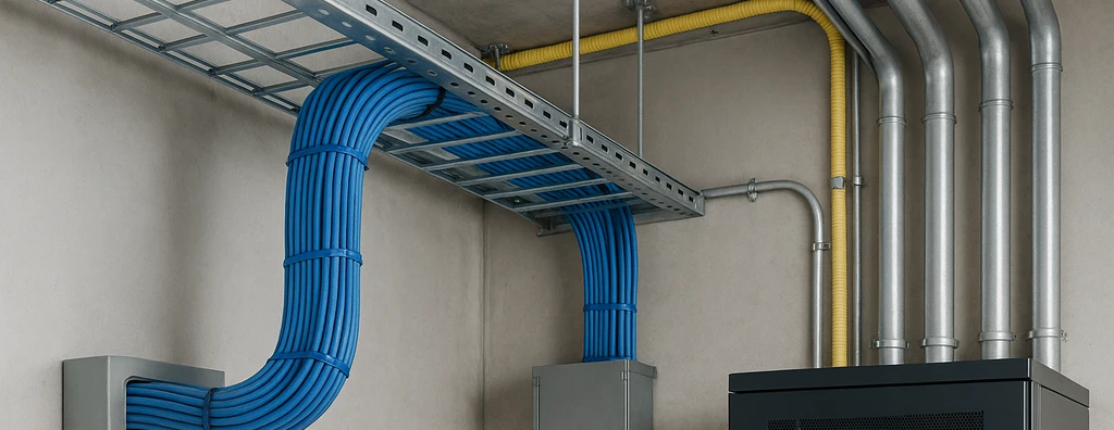
Cable Trays
Cable trays are open conduits, generally manufactured from galvanized steel or aluminum, used to accommodate large quantities of cables, especially on horizontal runs. They usually have a U or tray shape and allow visual inspection, ventilation, and easy access for future maintenance, expansion, or reconfiguration of the cabling system.
Cable Ladders
Cable ladders are metallic structures, generally ladder-shaped, indicated for accommodating large cable volumes in horizontal or vertical installations. They provide continuous mechanical support and favor cable management and heat dissipation in installations with high cable density.
Strut Channels
Strut channel is a type of perforated metallic pathway for cable routing, widely used in structured cabling installations to support and organize conductors, especially on horizontal routes.
Raceways
Raceways are closed or partially closed profiles, manufactured in PVC or metal, and installed on the surface of walls, baseboards, or furniture.
They are intended for cable routing in areas where civil interventions are not feasible.
This type of pathway stands out for easy installation, flexibility, and accessibility for cabling changes and expansions.
Shafts
Shafts are vertical compartments or passage ducts that cross multiple floors of a building, intended for the safe transposition of cables between different levels. These spaces allow centralization, protection, and organization of backbone and horizontal cables coming from different rooms and racks.
Raised Floor
Raised floor consists of a modular system made up of removable panels supported by adjustable pedestals, creating a technical space between the structural slab and the finished floor. This space is widely used to accommodate and distribute data, voice, and power cabling, especially in corporate environments and technical rooms.
Technical Criteria for Designing Internal Pathways
The design of cable pathways inside buildings must consider multiple regulatory and technical aspects, including:
- Sizing: Width, height, and quantity of conduits or trays must be planned according to current cable volume and future expansions.
- Minimum bend radii: Essential to avoid physical damage and preserve cable transmission characteristics, especially for optical fibers.
- Mechanical protection: Installation should take place in dry areas not subject to flooding, avoiding elevator shafts and stairwells. Compartments such as conduits and trays must be dedicated exclusively to structured cabling and cannot be shared with electrical distribution.
- Segregation compliance: If there is vertical sharing through shafts, all requirements of IEC 60364-4-41, IEC 60364-4-44, and IEC 60364-5-52 must be strictly met.
- Electromagnetic interference: Maximum separation between power and telecommunications cables is recommended, along with metallic barriers and separate routes to mitigate EMI.
- Grounding: For metallic materials, all pathways must ensure safe grounding and compliance with ABNT NBR 5410.
Structures and Spaces for External Cabling: Aerial and Underground
For interconnections between buildings, structured cabling may use underground or aerial pathways, each with specific technical requirements:
Underground Pathways
- These include buried conduits, manholes, inspection boxes, and ducts under public or private roads.
- They may be dedicated exclusively to structured cabling, such as direct-buried cable or conduit-based routing, or shared, such as in technical tunnels.
- It is essential that every access point preserves the environmental characteristics of the space, including sealing and watertightness.
Aerial Pathways
- These use poles, traction elements, self-supporting cables, and anchoring structures.
- Every aerial structure must ensure mechanical safety, strain relief at building entries, and protection against accidental stress.
Pull boxes and splice boxes should preferably be located on straight sections and must never form pathway bends. Cable splices may not be made inside pull boxes; specific and accessible boxes are required for that purpose.
Planning and Design of Pathways: Essential Guidelines and Considerations
Planning routes and pathways for structured cabling must address a broad set of factors that ensure construction feasibility, operational safety, and regulatory compliance:
- Existing structures and buildings: Analyze the building layout, constraints, interferences, and critical points.
- Growth forecast: Size the pathways considering expandability without disruption to the infrastructure.
- Geographic and environmental location: Assess the risk of exposure to water, heat, chemical agents, and physical damage.
- Accessibility and maintenance: Ensure easy access to inspection and intervention points without exposing cables to safety risks.
- Compatibility with other building systems: Coordinate electrical, plumbing, HVAC, and security specialty designs, minimizing crossings and interference.
- Local legislation and technical standard restrictions: Comply with all regulatory and technical requirements applicable to the type of infrastructure and building use.
Physical Security, Signage, and Access Control in Cabling Spaces
Spaces intended for structured cabling must present adequate levels of physical security, including:
- Restricted access: Physical controls must be implemented for technical areas through electronic devices, credentialing, and circulation limitations.
- Signage: Every technical area, rack, duct, and compartment must have signage in accordance with the organization’s security policy.
- Shared environments: Cables serving multiple buildings or occupants must be located in areas with restricted and controlled access, according to supplementary project guidelines.
No opening in spaces or infrastructure may compromise the environmental characteristics of the location. Cable entry points must provide proper strain relief and limit bend radii, protecting the integrity of terminations and shields.
Compartmentalization, Expandability, and Reliability Requirements
Cabling compatibility in relation to other systems is a critical aspect, addressed through the following technical requirements:
- Compartmentalization: The use of electrical compartments for structured cabling is prohibited; exclusive pathways, ducts, or trays are required.
- Expandability: Every pathway must provide spare capacity for future cable runs without requiring structural rework, minimizing operational risk.
- Reliability: Redundancies, alternate routes, and contingency diagrams must be considered in high-availability projects, especially in data centers and critical buildings.
Practical Implementation and Recommendations for Construction Execution
The implementation of pathways and spaces requires strict compliance with technical standards and detailed executive design:
- Materials: Select according to purpose, load, and environment, such as metallic trays for industrial areas, flame-retardant conduits for public-access areas, and PVC ducts for dry environments.
- Installation: Respect minimum separation between power and data pathways, limit the use of sharp bends, avoid unplanned crossings, and ensure robust fixation points.
- Inspection and testing: Perform detailed inspection of the entire installed infrastructure before cable pulling, with photographic documentation, as-built diagrams, and compliance reports.
- Commissioning: Final tests of connectivity, continuity, mechanical protection, grounding, and physical identification of the pathways for project acceptance.
Specific Considerations for Alternative Spaces and Shared Infrastructure
In situations where total segregation of structured cabling pathways is not feasible, additional requirements apply:
- Continuous metallic barriers: These must be used whenever cables from different systems coexist in the same shaft, minimizing noise coupling and ensuring adequate safety and system operation levels.
- Shared spaces: In service tunnels, ensure specific signage, labeling, maintenance zones, and accurate documentation of the occupancy of ducts and channels by each system.
Environmental Aspects, Resilience, and Durability of Pathways and Spaces
In environments subject to environmental aggressions such as humidity, excessive heat, and corrosive agents, pathway design must adopt high-durability solutions:
- Resistant materials: Use treated metals, anti-corrosion coatings, and engineered plastics.
- Sealing: Boxes, ducts, and building entries must be watertight, with sealing systems specified against the ingress of water, dust, and insects.
- Environmental monitoring: Use sensors, alarm systems, and predictive maintenance to anticipate failures caused by external agents.
The infrastructure must provide for easy maintenance, periodic inspection, and rapid response capability to incidents or technological changes.
Conclusion
The careful definition, sizing, and implementation of pathways and spaces intended for structured cabling are foundational steps for ensuring the performance, safety, and longevity of modern communication networks. Compliance with regulatory premises such as those established by NBR 16415, together with integration with other national regulations including ABNT NBR 5410, ABNT NBR 14565, ABNT NBR 16264, and IEC 60364, preserves the functional integrity of the infrastructure and significantly reduces the risks of failure, outage, or legal noncompliance.
Investment in robust technical solutions, scalability planning, and routine application of inspections and access controls is recommended so that IT and telecommunications infrastructure remains capable of supporting the constant evolution of business and technological demands. Engineering decision-making should always prioritize reliability, safety, and strict adherence to technical requirements, building solid foundations for critical operations and future expansions.
Relevant Links (Supplementary Technical Materials)
Telecommunications Network Design
Structured Cabling Design – Complete Guide
Structured Cabling Technical Standards
Standard 14565 – Structured Cabling
eBook – Why hire a Structured Cabling Design?
Dry Infrastructure – Cable tray occupancy rate
Fiber Optic Cable
Indoor Optical Distributor (IOD)
Testing and Performance
Network Certification for Structured Cabling Systems
Consulting for Structured Cabling Projects
Structured Cabling Installation
How to avoid common problems in Structured Cabling Systems?
Components and Subsystems
Main benefits of Structured Cabling
Topology and Architecture
Network Architecture and Topology – How to Ensure Performance
Network Topology: Types and Applications in Telecommunications Networks
Services