
Learn the main structured cabling subsystems and how campus backbone, building backbone, and horizontal cabling support scalable network infrastructure.
Check it out!
The structured cabling subsystems are integral parts of network infrastructure defined by technical standards such as NBR 14565 and ANSI/TIA-568.
Each subsystem has a specific role within the cabling system, ranging from the backbone to horizontal cabling, and including elements such as the work area, the telecommunications room, and the consolidation point.
Dividing the infrastructure into subsystems ensures organization and interoperability, while allowing the network to be installed, expanded, and maintained with standardization and predictable performance.
A Structured Cabling System compliant with technical standards is made up of several fundamental subsystems. Each subsystem has specific characteristics and functions, and all of them are essential to ensuring high-performance connectivity.
In this article, we will explore each of them in detail and understand how they contribute to creating a solid and scalable network.
Take a look!
[elementor-template id=”24446″]
Functional Cabling Elements
Structured Cabling is a robust, integrated infrastructure composed of essential components that work together to provide a flexible and scalable communications network.
In general applications, the functional elements of a cabling system are:
- Campus Distributor (CD);
- Building Distributor (BD);
- Floor Distributor (FD);
- Consolidation Point (CP);
- Consolidation Point Cable (CP cable);
- Telecommunications Outlet (TO);
- Multiuser Telecommunications Outlet (MUTO);
- Terminal Equipment (TE).
When interconnected through the Structured Cabling Subsystems, these fundamental elements establish a complete infrastructure designed to efficiently meet the communication requirements of a computer network, ensuring high performance and flexibility for future technological expansion.
Structured Cabling Subsystems
A Structured Cabling System is made up of three main subsystems:
- Campus Backbone;
- Building Backbone;
- Horizontal Cabling.
Let us understand the role of each subsystem:
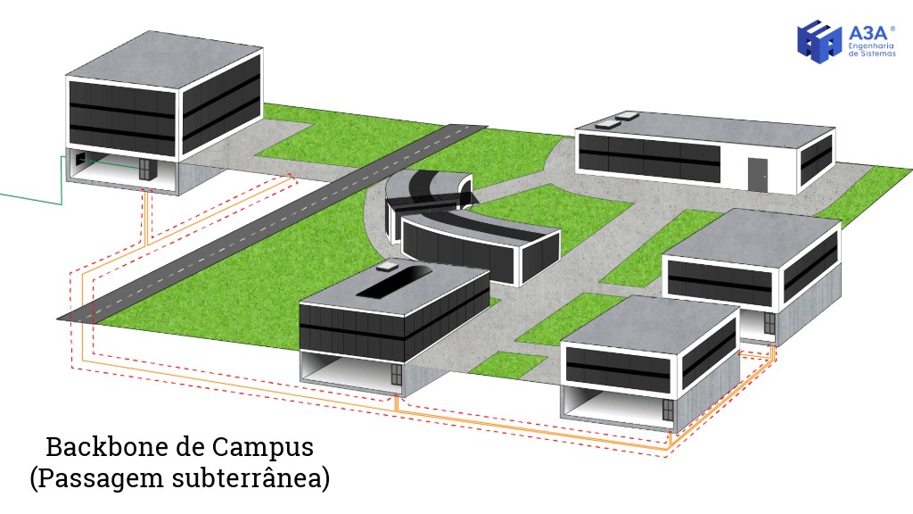
Campus Backbone
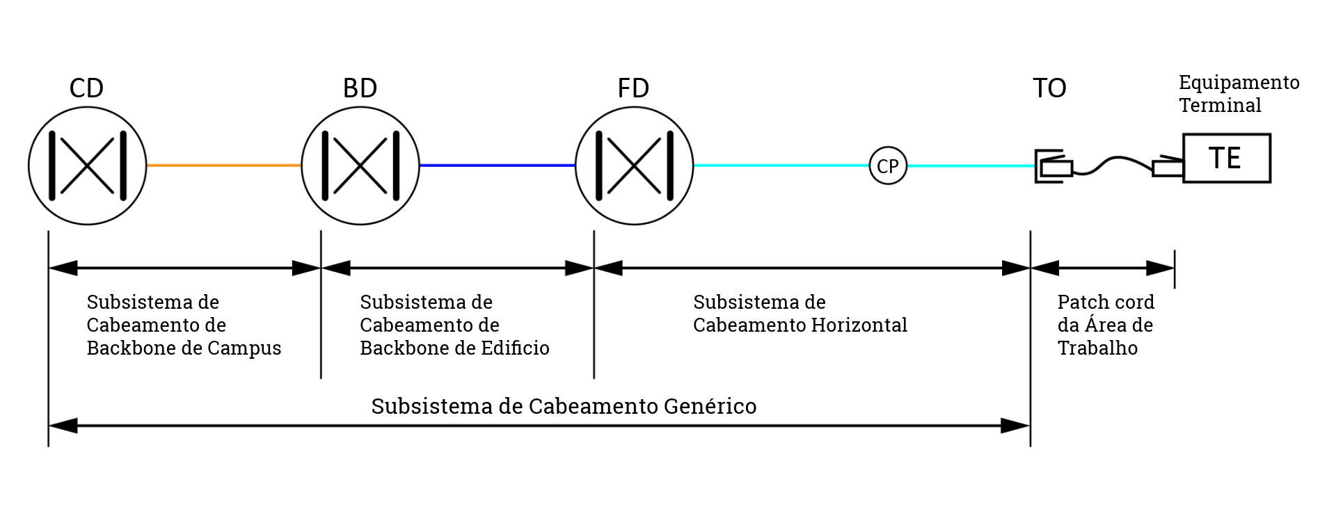
The Campus Backbone interconnects the campus distributor (CD) to the building distributors (BD).
The Campus Backbone Cabling Subsystem is composed of:
- The transmission medium used (UTP/STP or FO);
- Telecommunications Entrance Infrastructure;
- Network Equipment (Switches and Routers).
In applications where the distribution structure is not complete, such as on small university campuses or in small companies, the cabling infrastructure may be adapted.
In these situations, this subsystem may directly connect the campus distributor (CD) to the floor distributors (FD).
In certain circumstances, the Campus Backbone subsystem may also establish direct connections between Building Distributors (BD), eliminating the need to pass through the campus distributor (CD).
However, these direct connection arrangements must follow the rules of the Basic Hierarchical Topology.
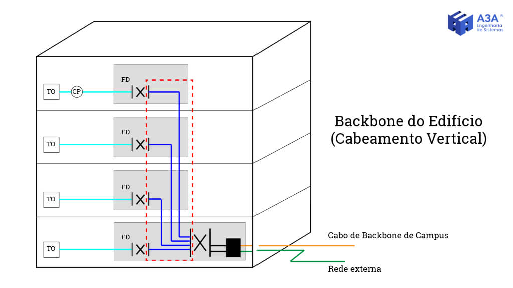
Building Backbone
The Building Backbone interconnects the building distributors (BD) to the floor distributors (FD).
The Building Backbone Cabling Subsystem is composed of:
- The transmission medium used (UTP/STP or FO);
- Network Equipment (Switches and Routers).
The Building Backbone cabling may also establish a direct connection between floor distributors (FD).
This can be done to simplify the infrastructure or to provide alternative and redundant paths, increasing network reliability.
This direct connection must also comply with the rules of the Basic Hierarchical Topology.
Horizontal Cabling
Horizontal Cabling interconnects the floor distributors (FD) to the telecommunications outlets (TO/MUTO).
The Horizontal Cabling Subsystem is composed of:
- The transmission medium used (UTP/STP or FO)
- Network Equipment (Switches and Routers);
- Consolidation point (optional);
- Telecommunications outlets.
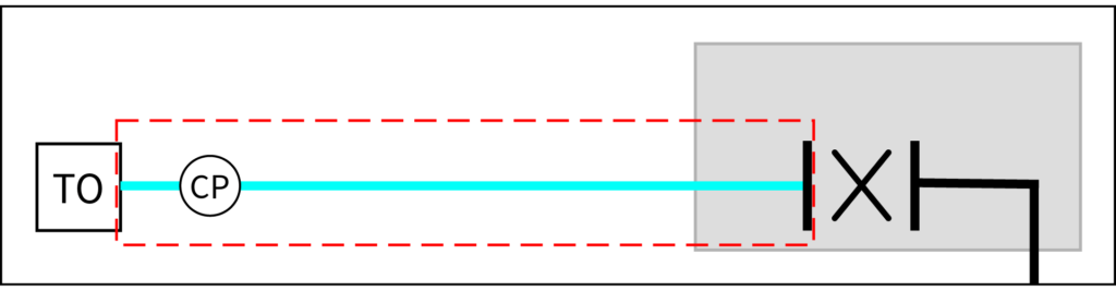
Technical standards set a maximum distance of 90 m for horizontal cabling. This distance is measured from the transition point between vertical cabling (building backbone) and horizontal cabling to the farthest telecommunications outlet.
Horizontal cables must be continuous from the floor distributor to the telecommunications outlet, unless there is a consolidation point.
The consolidation point is intended to simplify network changes and maintenance, allowing adjustments without the need to modify the main cabling. It is especially useful in environments where work area configurations are dynamic and subject to frequent reconfiguration.
The diagram below represents the complete interconnection of the subsystems that make up a Structured Cabling System.
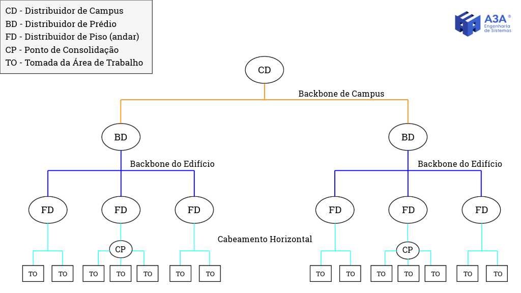
Although patch cords are used to connect transmission equipment to the Network Infrastructure, they are not considered an integral part of the subsystems.
Types of Connections
Connections between cabling subsystems may be classified as passive or active, depending on whether electronic equipment is present.
The configuration may be implemented through interconnection, which directly links terminal equipment to the cabling system, or cross-connect, which uses intermediary devices for enhanced system management.
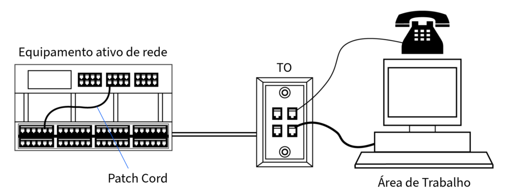
Interconnection
In interconnection, the fixed cable (horizontal or backbone) is terminated on a patch panel or optical distributor, with fixed termination on the rear side.
On the other side is the active device, usually a switch. The connection between the patch panel and the active device is made by means of a patch cord, whether for twisted-pair cabling or optical fiber.
This method is direct and simplified, providing an efficient connection between the patch panel and the active device.
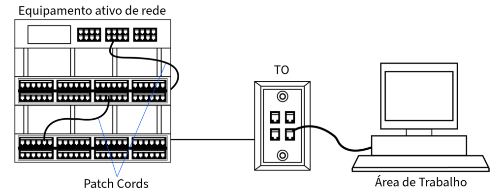
Cross-Connect
Cross-connect, on the other hand, involves more components and offers greater flexibility.
The horizontal or backbone cabling is terminated on a patch panel, and the active equipment is mirrored to another patch panel by means of equipment cords.
These cords connect all the switch ports and are terminated on the rear side of the mirrored patch panel.
This way, one patch panel mirrors the active equipment ports while another terminates the fixed cabling, with both connected through patch cords.
Both methods have advantages and disadvantages, are defined in technical standards, and are applied according to project requirements:
Interconnection is simpler and more economical, occupying less space and requiring fewer components. Cross-connect, while more complex and costly, offers the advantage of isolating move/add/change operations, facilitating maintenance and reducing the risk of damage to active equipment ports.
In environments with frequent changes, cross-connect allows all moves to be performed between patch panels, keeping switch ports permanently connected and protected.
This methodology enables agile reconfiguration of network connections without altering the main cabling. Such flexibility makes it possible to promptly adapt the system as network demands evolve, without requiring complex and time-consuming recabling processes.
This simplifies maintenance and allows for much more efficient and economical network expansion.

In scenarios where centralized optical cabling is adopted, connections may be made at distribution points using optical splices. However, this approach may limit the system’s flexibility in accommodating future reconfigurations because of the semi-permanent nature of splices.
Distributors, which are fundamental elements in this context, play an essential role by providing the infrastructure required to implement different Network Topologies, such as star and ring.
The subsystems are designed to support service integration and expansion, ensuring that the cabling system can adapt to different communication requirements and network configurations.
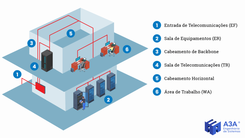
Six-Subsystem Model (ANSI/TIA-568)
The ANSI/TIA-568 standard defines a six-subsystem model for Structured Cabling.
In addition to the cabling interconnection subsystems, the six-subsystem model identifies certain spaces within the facility as critical system components.
In this context, it includes the Entrance Facility, the Equipment Room, and the Telecommunications Room, which may also be implemented as a Telecommunications Closet.
Structured Cabling Spaces
Structured Cabling Spaces are fundamental to the operation of Network Infrastructure.
They must be carefully planned to ensure that cabling can be easily installed, managed, and maintained, creating an environment conducive to efficient system performance.
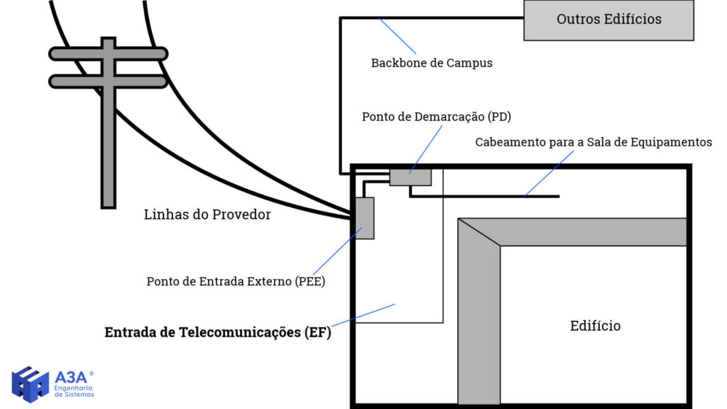
Telecommunications Entrance / Entrance Facility (EF)
The Telecommunications Entrance is the convergence point where campus and building backbone cables meet the circuits provided by external service providers.
The purpose of this space is to ensure access to the external connectivity and telecommunications services required for the organization’s operations.
This includes Internet connectivity, voice services, video services, and other communications applications. Therefore, it is critical that entrance cabling be properly designed and implemented, taking into account applicable technical specifications and standards.
In some cases, the Telecommunications Entrance may be integrated into the Equipment Room if the site structure allows or if required.
The entrance space should house only installations directly related to the Structured Cabling System and its supporting systems.
Equipment unrelated to telecommunications support systems (for example, water, gas, sewage piping, and general ducts) may not be installed in, pass through, or enter the entrance space.
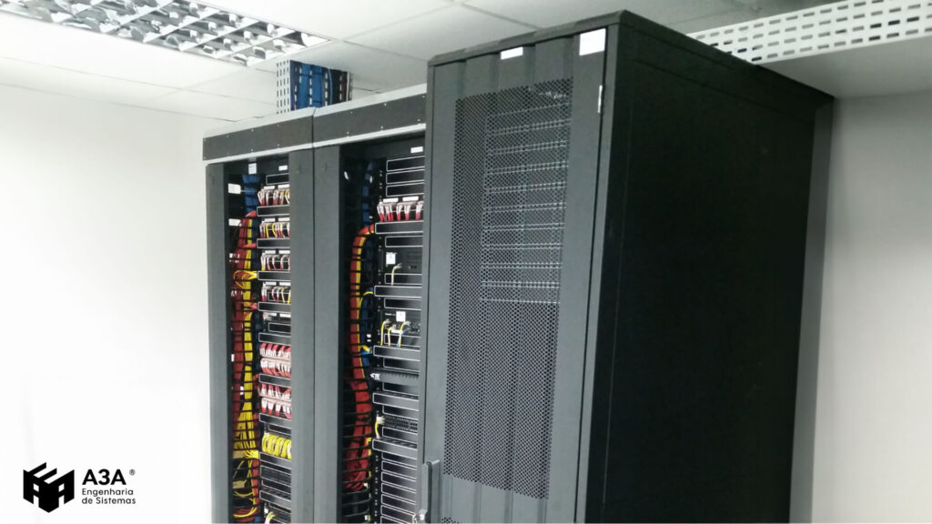
Equipment Room / Equipment Room (ER)
The Equipment Room is the space that houses critical IT and telecommunications infrastructure. Its design and implementation are fundamental to ensuring the integrity and high availability of critical services.
It is essential that access for the installation of heavy equipment be considered from the earliest stages of the project. It is recommended that the room be strategically located as close as possible to the building backbone, thereby facilitating connectivity and maintenance.
The room must be provided with robust infrastructure and Electronic Security measures, including Access Control Systems, Video Monitoring, and Fire Prevention Systems, to ensure equipment protection and the integrity of network services.
Internal organization of the room is crucial. Racks should be arranged to optimize airflow and simplify maintenance.
Effective cable management is essential to maintaining order, reducing interference, and enabling expansions or changes to the infrastructure with ease.
Cable selection is another critical point. High-quality cables should be specified, such as optical fiber or higher-category copper cables, in order to ensure stable performance and sufficient bandwidth.

In multi-story buildings, it is recommended that the room be located on an intermediate floor to facilitate cabling access to telecommunications rooms on other levels.
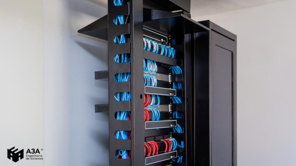
Telecommunications Room / Telecommunications Room (TR)
The Telecommunications Room is the space designated to act as the distribution and connection point for network cables coming from the various areas of the building.
This reserved space may range from a Telecommunications Closet to a room entirely dedicated to this function, depending on the size and needs of the infrastructure in question.
Its strategic location is defined to minimize cabling length and enable efficient cable distribution, both of which are fundamental to ensuring network performance.
The TR is usually located on each floor of the building or at strategic intermediate points. It enables interconnection between Vertical Cabling (Backbone) and Horizontal Cabling.
The Telecommunications Room design must take into account a ventilation and/or air-conditioning system as described by the applicable technical standards, in order to prevent overheating of installed active equipment.
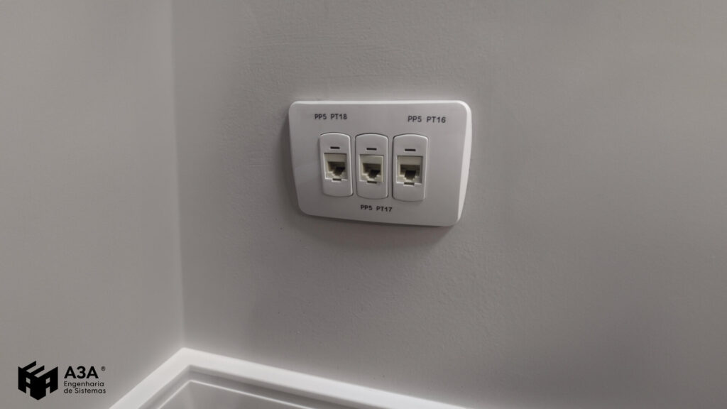
Work Area / Work Area (WA)
The Work Area is the interconnection point between terminal devices and the horizontal cabling system.
This is the space where users carry out their daily tasks, using equipment such as computers, IP phones, and printers.

In the Work Area, telecommunications outlets are used as the termination point for cables coming from the horizontal cabling. These outlets are connected to devices through patch cords.
Clear, standardized labeling and identification of outlets makes it easier to quickly locate connections and helps with cabling management and maintenance.
To ensure efficient connectivity, careful planning of the number of telecommunications outlets (network points) is essential.
This planning must take into account both the square footage of the facilities and the number of devices that will require connectivity, thereby ensuring that connectivity demands are fully met.
In addition, the standards establish maximum limits for the distance between telecommunications outlets and workstations, with the goal of ensuring that patch cords do not exceed a maximum length of 5 meters.
Structured Cabling Pathways
Structured Cabling Pathways are essential for protecting, organizing, and facilitating maintenance of the telecommunications infrastructure.
They ensure that cables remain safe and accessible, contributing to the integrity and performance of the cabling system as a whole. There are several types of pathways used to accommodate and protect cables:
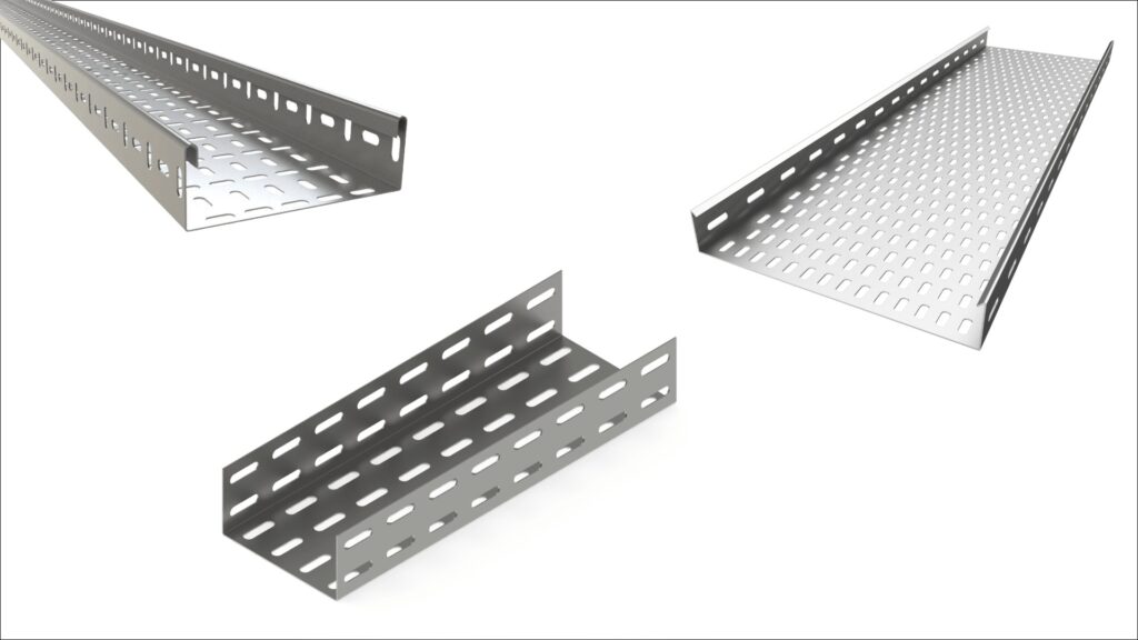
Cable Trays
Cable trays are perforated tray systems that provide a robust and flexible route for cabling.
They are ideal for large volumes of cables and are frequently used in industrial environments or wherever heavier and more complex cable distribution is required.
Conduits
Conduits are raceways that provide solid protection for cables, preventing physical damage and electromagnetic interference.
They may be made of different materials, such as PVC, steel, or aluminum, and are suitable for installations that require extra protection, such as outdoor areas or locations with heavy traffic.

Trunking
Trunking is a practical solution for cable management in office or residential environments. It allows for a clean, discreet installation and makes it easy to add or remove cables as needed.
Trunking can be installed on the floor, on walls, or on the ceiling, and it is available in a variety of sizes and styles to suit different aesthetic and functional needs.
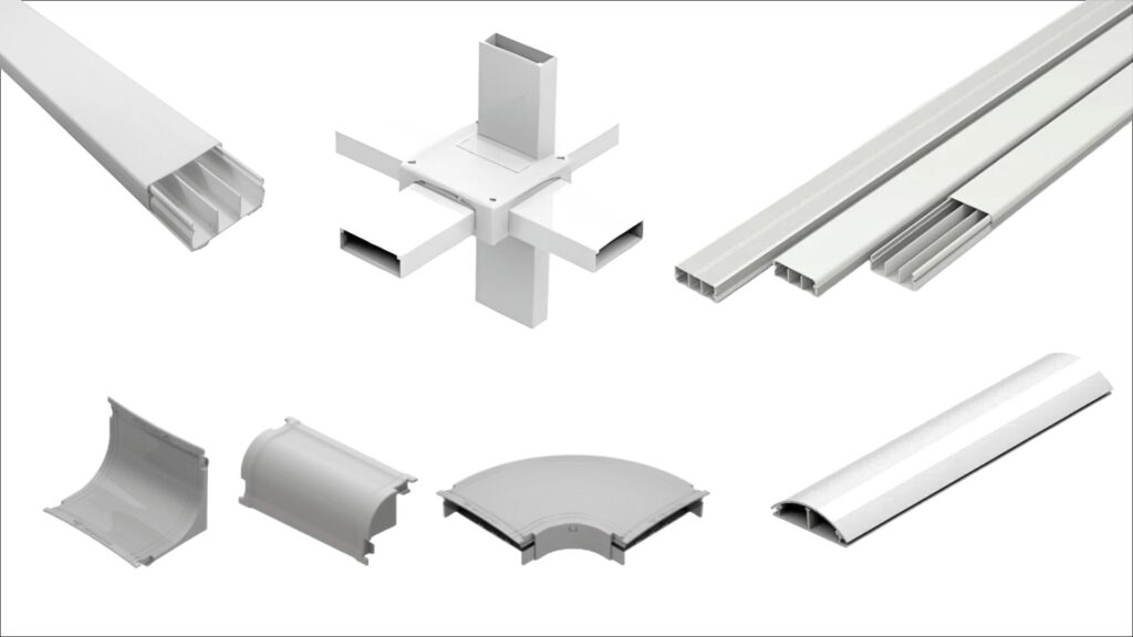
Source: Dutotec Catalog
Design of these cable pathways must align with the specific requirements of the cabling to be installed, following the guidelines of the applicable technical standards.
The amount of cabling, cable dimensions, minimum bend radii, and the possibility of future expansion must all be taken into account in order to properly size these pathways.

Key Benefits of Structured Cabling
By implementing a Structured Cabling System in compliance with standards and best practices, organizations can ensure a reliable, flexible, high-performance network capable of supporting today’s growing technological demands.
Below are the main benefits of a well-designed Structured Cabling System:
Flexibility: Structured Cabling Infrastructure is designed to be flexible and easily scalable. This characteristic allows the organization to adapt the network as its needs evolve. Adding new devices and services to the network becomes much simpler, without the need for major changes to the existing infrastructure.
Reliability: A properly planned Structured Cabling System results in a highly reliable network. Through the careful selection of certified cables, connectors, and components, connection failures are minimized, providing greater stability and service availability. This leads to less downtime and greater user satisfaction.
Simplified Management: With Structured Cabling, management of the network infrastructure becomes easier. Standardized components and logical cable organization make it easier to locate problems and perform corrective maintenance. This results in more efficient administration and less time spent on maintenance tasks.
Support for Multiple Services: One of the major advantages of Structured Cabling is its ability to support multiple services within a single infrastructure. In addition to data, it can also accommodate voice, video, and other applications. This enables the integration of converged technologies such as IP telephony and videoconferencing, making communications more efficient and reducing operating costs.
High-Speed Performance: A well-designed Structured Cabling System using appropriate cabling can support high data transmission rates. With the required bandwidth, the network can handle demanding applications, ensuring fast data transfers and a more agile, efficient network experience for users.
Conclusion
Structured Cabling Subsystems are essential components for ensuring reliable, efficient performance in communications networks. A well-designed Structured Cabling System provides a flexible, scalable infrastructure capable of supporting a wide range of applications, from voice and data to video and automation systems.
When designing and implementing a Structured Cabling System, it is essential to follow established Technical Standards and to consider both the quality of the components used and the experience and knowledge of the professionals involved in the project.
At A3A Engenharia de Sistemas, we are specialists in structured cabling and committed to delivering reliable solutions in compliance with established standards. Our team of certified professionals has the knowledge and experience required to ensure excellence in every project.
We work in partnership with renowned companies in the sector such as COMMSCOPE, FURUKAWA, NEXANS, and LEGRAND, all of which are leaders in network infrastructure solutions. These solid partnerships allow us to offer our clients the most advanced technologies and the best practices in the market.
Our certified team is ready to support you from planning through implementation of your structured cabling project. We work closely with our clients, understanding their needs and delivering customized, high-value solutions.
Contact us and find out how to boost the connectivity and efficiency of your Network Infrastructure.
Relevant Links (Supplementary Technical Materials)
Telecommunications Network Design
Structured Cabling Design – Complete Guide
Structured Cabling Technical Standards
Standard 14565 – Structured Cabling
eBook – Why Hire a Structured Cabling Design Project?
Cable Routing – Dry Infrastructure
Fiber Optic Cable
Internal Optical Distributor (IOD)
Testing and Performance
Network Certification for Structured Cabling Systems
Consulting for Structured Cabling Projects
Structured Cabling Installation
How to avoid common problems in Structured Cabling Systems?
Components and Subsystems
Key Benefits of Structured Cabling
Network Cabling – General Overview
CAT5e vs. CAT6 Network Cabling
CAT6 vs. CAT6A Network Cabling
Topology and Architecture
Network Architecture and Topology – How to Ensure Performance
Network Topology: Types and Applications in Telecommunications Networks
Services
Normative References
“NBR 14565 – Structured Cabling for Commercial Buildings” – ABNT (Brazilian Association of Technical Standards)
“ISO/IEC 11801 – Generic Cabling for Customer Premises” – ISO/IEC (International Organization for Standardization) & International Electrotechnical Commission
“ANSI/TIA 568 – Generic Telecommunications Cabling for Customer Premises” – ANSI/TIA (American National Standards Institute) & Telecommunications Industry Association
“What are structured cabling services and their corresponding technical responsibilities?” – CREA (Regional Council of Engineering and Agronomy)
“Structured Cabling Systems: the Fact File” – CommScope
Frequently Asked Questions
According to NBR 14565, the structured cabling system is divided into six main subsystems:
Entrance cabling – Connects the public network to the demarcation point inside the building.
Equipment room (MDF) – Houses the main active network equipment and centralizes backbone connections.
Backbone cabling – Responsible for interconnecting technical rooms, floors, or buildings (on campuses).
Telecommunications room (IDF) – Termination and redistribution point for horizontal cabling.
Horizontal cabling – Connects the telecommunications room to network points in work areas.
Work area – Final connection point for user equipment such as computers, IP phones, and access points.
A Structured Cabling System (SCS) is a standardized infrastructure of cables, connectors, racks, cable trays, patch panels, and active network equipment that provides the foundation for a telecommunications network to operate efficiently.
A Structured Cabling System works through the installation of various network components, including cables, active equipment, patch panels, and other devices, following technical standards and specifications.
A cabling structure is a generic system organized into interconnected subsystems, composed of cables, connectors, and devices designed to support multiple services such as voice, data, video, and building automation in a standardized, flexible, and application-independent way, allowing modifications and expansions without major intervention in the physical infrastructure.
The structured cabling system is designed to meet connectivity needs in corporate, commercial, industrial, and residential environments, providing a reliable, high-performance network.
The most common are UTP cable (unshielded twisted pair), STP cable (shielded twisted pair), coaxial cable, and optical fiber. Each one has different applications and transmission capabilities.
UTP (Unshielded Twisted Pair) has no shielding. It is cheaper and used in environments with low levels of interference. STP (Shielded Twisted Pair), on the other hand, has shielding that reduces electromagnetic interference and is recommended for industrial environments or locations with high electromagnetic pollution.
The main standards are ABNT NBR 14565 (Brazil), ISO/IEC 11801 (international), ANSI/TIA-568 (North America), and NBR 16264 for Data Centers. They define installation, performance, and testing rules.
Horizontal cabling connects telecommunications outlets to distribution rooms on the same floor, while vertical cabling, or backbone, interconnects different floors or buildings, carrying data between main and floor distributors.
It is the main cabling that connects telecommunications rooms, data centers, or buildings to each other. It usually uses higher-capacity media, such as optical fiber or higher-category copper cabling.
Electrical engineers, network engineers, telecommunications technicians, network infrastructure designers, and specialized companies responsible for corporate network design and deployment.