Understand network cable certification parameters: wire map, length, insertion loss, return loss, NEXT, ACR, alien crosstalk, PoE, PASS/FAIL, retesting, and acceptance documentation.
Check it out!
Network-cable certification parameters are the measurements used to verify whether copper structured-cabling links comply with technical standards, the category specified in the design, and infrastructure acceptance criteria.
In structured cabling projects, corporate buildings, data centers, industrial networks, IP CCTV, corporate Wi-Fi, and critical systems, these parameters should not be analyzed as isolated numbers. They indicate whether the permanent link, channel, or MPTL termination provides performance compatible with the intended application.
This article explains the main certification parameters for twisted-pair cabling, including wire map, length, resistance, insertion loss, return loss, crosstalk, and signal-to-noise relationships, with emphasis on technical reports, As-Built documentation, and installation acceptance.
Summary: Certification Parameters for Copper Cabling
| Parameter | What it verifies | Acceptance impact |
|---|---|---|
| Wire map | Continuity, pairs, reversals, and shorts | Confirms correct link termination |
| Length | Electrical length of the link and standard limit | Validates whether the channel or permanent link is within the limit |
| Insertion loss | Signal attenuation along the cable | Indicates transmission performance within the category |
| Return loss | Reflections caused by discontinuities | Helps identify termination, impedance, or physical damage |
| Crosstalk | Interference between cable pairs | Affects performance in Gigabit and 10 Gigabit Ethernet networks |
| Report | Record of measurements and final result | Forms part of As-Built documentation and technical acceptance |
Test Configuration: What Must Be Defined Before Testing?
Certifying a link is not simply connecting the certifier and pressing Test. Before measurement, the technician must select the actual installed configuration, category or class, link type, and corresponding standard limit. A PASS result against the wrong limit does not demonstrate design compliance.
| Configuration | What it represents | Typical use |
|---|---|---|
| Permanent link | Fixed cabling between permanent terminations | Acceptance of installed horizontal infrastructure |
| Channel | Permanent link mais patch cords/equipment cords previstos no modelo | Validation of the complete operational channel |
| MPTL | Link with a field-terminated plug at the device end | Cameras, access points, and other fixed devices when the configuration is specified |
| Patch cord | Cord assembled as a specific component | Cord testing using the appropriate method and adapters |
Test adapters must also correspond to the selected configuration. Permanent-link adapters, channel adapters, and MPTL-specific adapters are not interchangeable simply because they use physically similar connectors.
Acceptance, Compatibility, and Reference Testing
Annex A of ABNT NBR 14565 distinguishes three purposes. Acceptance testing validates installed cabling by measuring required parameters and comparing them with category limits. Compatibility testing is used to evaluate an installation formed by known or unknown components. Reference testing compares models and instruments under controlled conditions and may include properties that are impractical to measure in the field.
| Parâmetro | Acceptance under NBR 14565 | Main function |
|---|---|---|
| Mapping/continuity | Normative | Detect opens, shorts, and termination errors |
| Comprimento | Calculated | Verify estimated electrical length |
| Perda de retorno | Normative | Evaluate reflections and impedance discontinuities |
| Perda por inserção | Normative | Measure signal attenuation |
| NEXT | Normative | Evaluate near-end crosstalk between pairs |
| PS NEXT | Calculated | Evaluate the combined effect of interfering pairs |
| ACR / PS ACR | Calculated | Evaluate margin between useful signal and crosstalk |
| ACR-F / PS ACR-F | Calculated | Evaluate far-end crosstalk compensated for attenuation |
| Propagation delay | Normative | Measure signal travel time |
| Delay skew | Normative | Measure delay difference between pairs |
Calibration, Adapters, and Test-Limit Selection
Test traceability depends on both instrument and process. Before a certification campaign, check the condition of adapters and reference cords, software version, selected limit, calibration date, and operator identification. Worn test connectors or an incorrect adapter can produce failures that do not belong to the link — or mask real problems.
It is also advisable to record in the design or test plan which standard, category/class, configuration, and retest criteria will be adopted. This prevents different teams from testing the same installation using different parameters.
Wire Map Tests
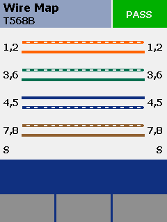
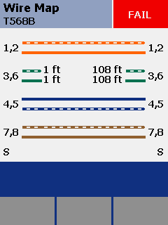
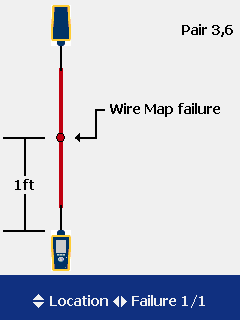
The wire-map test verifies the integrity of the connections of all four conductor pairs in a twisted-pair cable, ensuring that each conductor is connected correctly according to the applicable standards.
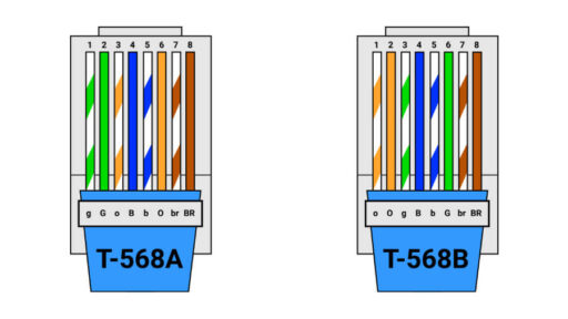
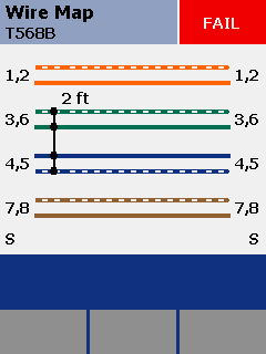
During this test, all eight conductors are evaluated for compliance with normative specifications. The main checks include:
- pin-to-pin continuity;
- short circuits;
- pair transposition;
- pair reversal;
Propagation Tests
Propagation tests are used to evaluate signal-transmission performance over a physical medium.
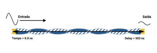
Propagation Delay is the time required for a signal to travel the full cable length from one point to another, measured in nanoseconds (ns). This delay is one of the factors involved in length limits for copper telecommunications cabling.
In networks using collision-detection mechanisms, such as legacy Ethernet operation, propagation delay must remain within the applicable limits so timing requirements are met. The standards define a maximum horizontal delay of 570 ns for cabling up to 100 meters.
Because each pair in a network cable has its own twist rate, delay varies from pair to pair.
Delay Skew is the difference in propagation time between the fastest and slowest pairs in a twisted-pair cabling system.
This variation must not exceed 50 ns for any link segment up to 100 meters.
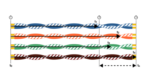
This difference can significantly affect data transmission, especially applications that use all four pairs, such as Gigabit Ethernet.
Although receivers are designed to tolerate small propagation-delay differences, excessive delay skew can prevent correct reconstruction of the original signal.
Cable Length
Cable-length measurements are derived from propagation delay.
This calculation is based on Nominal Velocity of Propagation (NVP), generally expressed as a percentage (%) of the speed of light in vacuum (300,000 km per second).
The NVP value is provided by manufacturers and generally ranges from 56% to 78%, depending on cable design and materials. The measurement is evaluated based on the shortest pair within the cable.
Acceptance criteria for cable length are based on the maximum permitted channel length (100 m) or permanent-link length (90 m), together with a 10% measurement allowance associated with NVP, as specified by the applicable standards.
In the example below, the measured length based on the shortest pair exceeds the nominal limit by 0.8 m but still passes because of the applicable 10% measurement allowance.
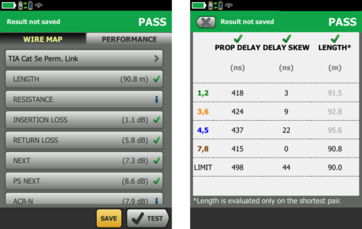
Cable length matters for several reasons. As cable length increases, insertion loss increases, reducing signal margin and potentially affecting transmission performance.
The conductors inside the cable are typically slightly longer than the cable’s linear length because of pair twisting, which is used to reduce electromagnetic interference and preserve signal integrity.
In practice, network layout should avoid unnecessarily long routes and keep connection points within the dimensional limits and architecture established by the design.
Conductor Resistance
Resistance is the opposition to electric-current flow in a conductor. In structured cabling systems, conductor resistance must remain within applicable limits to support the intended data and power applications.
Cable resistance is directly proportional to length and inversely proportional to conductor cross-sectional area. Longer cables or smaller conductors therefore have higher resistance.
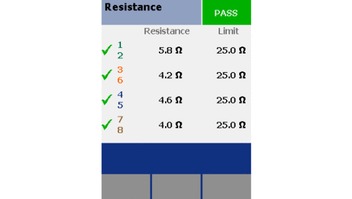
Resistance also increases with temperature, so cables operating in hotter environments exhibit higher resistance. This should be considered in network designs for elevated-temperature environments.
Resistance becomes even more important in PoE (Power over Ethernet) applications. A critical parameter in this context is resistance balance, the difference in resistance between the two conductors of a pair.
Resistance unbalance can create current imbalance in the cabling channel, potentially affecting PSE transformer operation and proper power delivery.
Signal Attenuation (Insertion Loss)
Insertion Loss is the attenuation a signal experiences while propagating through a cable. It is expressed in decibels (dB) and represents signal loss caused by the electrical characteristics and energy dissipation of the cabling.
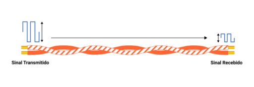
Insertion loss varies with signal frequency. Higher frequencies generally experience greater attenuation, so loss increases as frequency rises.
Insertion loss must be measured across the frequency range applicable to the channel. For example, a Category 5e channel is evaluated from 1 MHz through 100 MHz, while Category 6 links are evaluated from 1 MHz through 250 MHz.
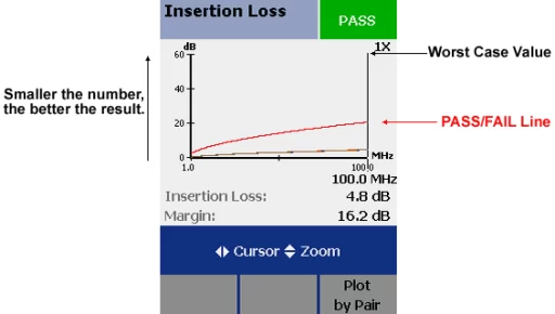
Insertion loss also increases with link length, so longer cabling has greater attenuation.
Return Loss
Return Loss indicates how much signal is reflected back toward the transmitter because of discontinuities or imperfections in the transmission path. It is expressed in decibels (dB) from the relationship between transmitted and reflected power.
A higher Return Loss value represents better performance because a smaller proportion of the signal is reflected back toward the transmitter.
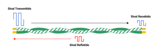
Return Loss can be degraded by physical cable damage such as excessive bends or crushing that introduce impedance discontinuities. Poor termination practices, such as excessive untwisting of pairs, can also disturb impedance uniformity and increase reflections.
Water ingress is another significant source of Return Loss degradation because it changes the dielectric properties of the cable insulation and affects characteristic impedance.
Crosstalk
Crosstalk occurs when a signal transmitted on one pair interferes with another pair in the same cable. This can introduce noise and degrade data-transmission performance.
Several crosstalk-related parameters are considered during structured-cabling certification:
NEXT
NEXT, or Near-End Crosstalk, measures interference at the same end of the cable where the signal is transmitted. It represents the amount of signal coupling from one pair into another near the signal source.
The interference results from electromagnetic coupling between pairs. When an electrical signal is transmitted through one pair, it creates a surrounding electromagnetic field.
If another pair is sufficiently close, this field can induce an unwanted signal in that pair.
NEXT is expressed in decibels (dB). A higher value indicates better isolation between pairs and therefore greater crosstalk margin.
NEXT is especially relevant in high-speed, high-frequency applications, where insufficient margin can contribute to transmission errors and reduced reliability.
PSNEXT
PSNEXT is a cumulative measure of near-end crosstalk at the transmitting end.
It is calculated from the combined NEXT contributions of the other pairs at the near end.
In applications such as Gigabit Ethernet that use all 4 pairs simultaneously, PSNEXT is important because it represents the combined interference environment rather than a single pair-to-pair relationship.
During PSNEXT testing, the instrument evaluates the combined crosstalk contributions from the other pairs.
The objective is to evaluate the cumulative crosstalk a given pair can experience when the other pairs are transmitting.
PSNEXT helps verify that the cabling maintains sufficient margin when all pairs are active simultaneously.
Signal-to-Noise Relationships
A Signal-to-Noise Relationships (Signal-to-Noise Ratio), é uma métrica expressa em decibéis (dB) que quantifica a clareza de um sinal em relação ao ruído de fundo.
In structured cabling, these relationships are important indicators of transmission margin.
Certification includes calculated relationships such as ACR-F (Attenuation to Crosstalk Ratio at Far-end) and PSACR-F (Power Sum ACR-F).
ACR-F
ACR-F, historically also referred to as ELFEXT, represents far-end crosstalk normalized by insertion loss.
By accounting for insertion loss, ACR-F provides a more meaningful indication of far-end crosstalk margin.
This supports evaluation of cabling performance with respect to far-end crosstalk among pairs.
PSACR-F
PSACR-F, historically also referred to as PSELFEXT, applies a power-sum approach to far-end crosstalk contributions from multiple pairs.
Like PSNEXT, PSACR-F is important in applications that use all four pairs for transmission, including Gigabit Ethernet.
PSACR-F considers the combined far-end crosstalk contributions affecting a given pair.
This allows evaluation of cumulative crosstalk effects across the cable pairs.
PSACR-F therefore provides a broader view of far-end crosstalk performance under simultaneous pair activity.
Adequate margins support reliable operation in systems that use all pairs for data transmission.
Certification parameters should be evaluated together with the cabling design, specified category, measurement method, final report, and infrastructure acceptance criteria.
See also services and solutions related to cabling specification, implementation, validation, and technical governance.
ACR-N, PS ACR-N, and Performance Margins
In addition to NEXT, certification includes calculated relationships between insertion loss and crosstalk. ACR-N expresses the margin between NEXT and insertion loss, while PS ACR-N considers the combined effect of the other pairs. These values must be interpreted against the standard limit selected in the instrument, not as an independent link score.
Alien Crosstalk in Cat6A and Class EA
In Class EA/Category 6A links, interference may also come from neighboring cables. This phenomenon is alien crosstalk. ABNT NBR 16869-1 provides for link sampling to verify it when applicable to the installed system.
| Number of links | Sampling |
|---|---|
| 3 to 150 | 10% |
| 151 to 3,200 | 15% |
| 3,201 to 35,000 | 20% |
Link selection should represent higher-exposure scenarios. A Cat6A system should not be accepted solely on internal cable parameters when an applicable alien-crosstalk requirement has been omitted.
Resistance, Unbalance, and PoE
PoE applications increase the importance of DC parameters. High resistance increases voltage drop and heating, while unbalance can distribute current unevenly. Design, specification, termination, and certification must be evaluated together when the network powers cameras, access points, phones, or IoT devices.
The certification report does not replace PoE-budget sizing, but it can reveal anomalies associated with conductors, connections, and terminations. CCA cables, unsuitable conductor gauges, and high-resistance connections are incompatible with professional infrastructure.
How to Interpret PASS, FAIL, and Diagnose Failures
A passing link must meet the selected limit for every required parameter. A FAIL must trigger diagnosis, correction, and retesting — never be replaced by a simple continuity test.
| Predominant failure | What to investigate |
|---|---|
| Wire map | Open, short, split pair, reversal, or termination |
| NEXT / PS NEXT | Untwisting, connectorization, compression, or incompatible component |
| Return Loss | Bend, crushing, splice, impedance, or termination |
| Insertion Loss | Length, temperature, cable, or category |
| Resistência | Conductor, gauge, length, or connection |
| Alien crosstalk | Bundles, proximity, and cable organization |
After correction, the link must be retested. Nonconformance history should be preserved when required by the contract, quality plan, or commissioning process for traceability.
Certification and Technical Acceptance Flow
A reliable certification campaign starts in the design and ends in documentation. Limits, identifiers, and test configuration must be defined before field work; results must be associated with the correct outlet; failures must trigger correction and retesting; and the approved set must become part of the As-Built.
What Should Be Included in the Certification Report?
- unique link identifier and correspondence with drawings;
- tested category or class and configuration;
- selected standard limit;
- certifier model, serial number, and calibration;
- adapters and test type used;
- date, time, and operator;
- results and margins by parameter;
- record of corrections and retests;
- native electronic file or auditable export.
Certification, As-Built, and Traceability
A test file has operational value only if it can be associated with the physical point. Identification should correspond to the outlet, patch-panel port, rack, room, and drawing. When this chain is lost, certification no longer functions as objective acceptance evidence.
At handover, results should form part of the commissioning dossier or As-Built documentation together with updated drawings, port maps, closed punch-list items, and other records required by the project.
Conclusion
Technical acceptance requires traceable evidence.
Certification reports, outlet identification, port maps, and As-Built documentation must correspond to what was actually installed.
Network-cable certification parameters make it possible to evaluate whether a copper link meets applicable standard limits, the specified category, and the requirements defined in the structured-cabling design.
Wire map, length, resistance, insertion loss, return loss, crosstalk, and signal-to-noise relationships support the certification report, As-Built documentation, and technical acceptance of the installed infrastructure.
Technical References
[1] ABNT. ABNT NBR 14565:2019 — Structured cabling for commercial buildings. Available at: https://www.abntcatalogo.com.br/
[2] ABNT. ABNT NBR 16869-1:2020 — Structured cabling — Part 1: Planning requirements. Available at: https://www.abntcatalogo.com.br/
[3] ISO/IEC. ISO/IEC 11801-1:2017 — Information technology — Generic cabling for customer premises — Part 1: General requirements. Available at: https://www.iso.org/standard/66182.html
[4] IEC. IEC 61935-1 — Specification for the testing of balanced and coaxial information technology cabling — Part 1: Installed balanced cabling. Available at: https://webstore.iec.ch/
[5] IEEE. IEEE 802.3 — Ethernet. Available at: https://www.ieee802.org/3/
Frequently Asked Questions
Key parameters include wire map, length, insertion loss, return loss, NEXT, PS NEXT, ACR-N, PS ACR-N, ACR-F, PS ACR-F, propagation delay, and delay skew, according to the selected limit and test configuration.
The permanent link represents the fixed infrastructure between permanent terminations. The channel also includes the cords defined by the application model and must be tested with the corresponding configuration and adapters.
PASS means the link met the selected limit for the required parameters. The result is valid only if category, standard, configuration, and adapters are correctly defined.
The failure should be diagnosed by its predominant parameter, corrected, and the link retested. A continuity test does not replace certification retesting.
When applicable to a Class EA/Category 6A system, NBR 16869-1 provides for link sampling to evaluate alien crosstalk. The test plan should define the sample before acceptance.
Yes. Results should be traceable to the physical point and associated with drawings, port identification, rack, and infrastructure handover documentation.
Additional Technical Materials
Related Solutions
Related Services
Main Content on the Topic
- Network Cabling Certification
- How to Certify a Structured Network
- Guia Completo sobre Structured Cabling
