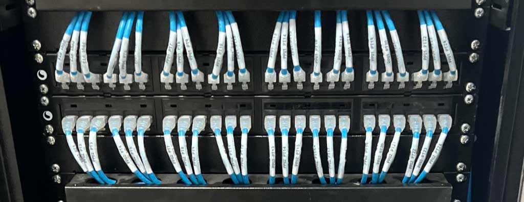
Learn how to organize and size a network rack: components, patch panels, switches, DIOs, space, reserve capacity, PoE, power, ventilation, labeling, documentation, and technical acceptance.
Check it out!
A network rack is the technical cabinet used to install, protect, organize, and manage telecommunications equipment and components such as switches, patch panels, DIOs, routers, firewalls, servers, UPS systems, cable managers, power strips, and other elements of the physical network infrastructure.
Rack organization directly affects maintenance, availability, expansion, documentation, ventilation, operational safety, and troubleshooting time in the event of failures. In corporate environments, data centers, schools, hospitals, industrial facilities, condominiums, commercial buildings, and public agencies, a disorganized rack can turn a simple intervention into a slow, risky, and untraceable activity.
This article explains how to organize a network rack, which components should be considered, how to size capacity, space, ventilation, and technical reserve, and how to coordinate patch panels, switches, DIOs, cabling, power, labeling, documentation, certification, and infrastructure management.
What Is a Network Rack?
A network rack is a standardized cabinet or structure for mounting telecommunications and IT equipment. It concentrates the elements used to distribute, connect, and manage the physical and logical network of an environment.
A rack may contain:
- metal patch panels;
- DIOs and optical panels;
- access or distribution switches;
- routers and firewalls;
- servers or appliances;
- UPS systems;
- power strips;
- horizontal and vertical cable managers;
- fixed or sliding shelves;
- cable guides;
- CFTV, access control, automation, or IP telephony equipment.
The rack is therefore a critical infrastructure point. If it is not properly designed, labeled, and organized, the network becomes difficult to operate, maintain, and expand.
Why Is Rack Organization Important?
Organizing a rack is not simply about making cables look aligned. Proper organization creates a technical structure that facilitates maintenance, reduces the risk of accidental disconnections, improves airflow, simplifies moves and changes, and increases documentation reliability.
A well-organized rack helps to:
- reduce troubleshooting time;
- quickly identify outlets, ports, and equipment;
- avoid handling permanent cabling;
- improve ventilation and heat dissipation;
- separate power and telecommunications;
- facilitate future expansion;
- preserve cable bend radius;
- reduce mechanical stress on ports and connectors;
- improve operational safety;
- support certification and technical acceptance;
- keep documentation consistent with the actual installation.
A disorganized rack, on the other hand, makes ports harder to identify, increases the risk of disconnections, creates crossed cables, complicates equipment replacement, impairs ventilation, and reduces network reliability.
An Organized Rack Is Not Just About Appearance
Appearance is a consequence of good organization, but it should not be the primary objective. The focus should be functionality, documentation, maintenance, and predictability.
A rack may look visually “clean” and still be technically inadequate if it lacks labeling, technical reserve, proper segregation, updated documentation, compatible patch cords, organized power distribution, and expansion space.
Likewise, a superficial correction made only to improve how the rack looks in a photo may conceal design problems such as missing patch panels, permanent cabling connected directly to switches, no DIO, mixed power and data cabling, lack of grounding, patch cords without a standard, and no port map.
A network rack should be treated as part of the design, not merely the installation.
Proper organization depends on patch panels, switches, DIOs, power, labeling, ventilation, documentation, certification, and technical reserve.
Main Components of a Network Rack
Rack composition varies by environment, but some components are common in corporate networks.
| Component | Function in the rack | Relationship to structured cabling |
| Patch panel | Terminates and organizes permanent copper cables | Connects horizontal cabling to switches through patch cords |
| Switch | Active Ethernet switching equipment | Activates network outlets connected to the patch panel |
| DIO or optical panel | Terminates and organizes optical fibers | Used for optical backbones and interconnections between racks/buildings |
| Horizontal cable manager | Organizes patch cords at the front of the rack | Reduces crossings and stress on ports |
| Vertical cable manager | Organizes cables along the sides | Helps in racks with higher port density |
| Shelf | Supports equipment that is not mounted directly to rails | Useful for appliances, converters, and smaller equipment |
| Power strip | Distributes electrical power | Must be positioned safely with adequate separation |
| UPS | Maintains power during supply failures | Must be sized according to load and required runtime |
| Labels and identification | Provide traceability | Must correspond to drawings, maps, and certification reports |
For a deeper look at the role of the patch panel, see the article Patch Panel: What It Is, What It Does, and How to Use It in Network Racks.
Patch Panel, Switch, and Patch Cords: How Should They Be Organized?
The arrangement of patch panels, switches, and patch cords is one of the most important aspects of a rack. Horizontal cabling should terminate at the patch panel, and switches should be connected using patch cords.
Avoid connecting permanent cables directly to switches. This practice makes maintenance more difficult, increases the risk of damage to horizontal cabling, and undermines infrastructure organization.
Good practices include:
- using patch panels compatible with the cabling category;
- positioning patch panels close to the corresponding switches;
- using patch cords of appropriate length;
- avoiding excessively long cables;
- preserving bend radius;
- avoiding mechanical stress on switch or patch-panel ports;
- maintaining a color standard where it provides operational value;
- labeling ports and outlets;
- documenting the connection map.
The channel category depends on the complete system formed by the cable, connector, outlet, patch panel, patch cord, and installation. Therefore, the choice among Cat5e, Cat6, and Cat6A must consider the entire system, not just the cable. See also Types of Network Cables and Cat6 vs. Cat6A.
Cable Organization Inside the Rack
Cable organization must preserve functionality and maintainability. Overly tight cables, excessive bends, unnecessary crossings, and lack of identification increase failure risk and make interventions more difficult.
Important criteria include:
- separating data and power cables;
- using horizontal and vertical cable managers;
- avoiding excessive slack at the front;
- routing patch cords through predictable paths;
- protecting optical cables from excessive bending;
- avoiding rigid ties that deform cables;
- maintaining access to ports;
- preserving equipment ventilation;
- avoiding obstruction of switch and server exhaust paths.
In fiber-optic networks, DIOs, fiber patch cords, and splice trays require even greater care because optical connectors are sensitive to contamination, bending, and improper handling.
Rack Identification and Documentation
An organized rack without identification remains an operational problem. Labeling must allow any outlet to be traced from the telecommunications outlet to the patch-panel port, switch port, rack, technical room, and project documentation.
Documentation may include:
- patch-panel port map;
- switch port map;
- telecommunications outlet drawings;
- rack and technical-room identification;
- certification report for each outlet;
- list of installed equipment;
- asset inventory;
- IP addressing, where applicable;
- backbone diagram;
- as-built documentation.
In larger environments, inventory, IPAM, DCIM, and source-of-truth tools such as NetBox can help keep the infrastructure documented and auditable.
How to Size a Network Rack
Rack sizing should start with the number of terminations, active equipment, optical panels, cable managers, power requirements, expansion needs, and maintenance conditions. Selecting a cabinet solely by the number of available rack units tends to produce two opposite errors: insufficient space for cables and equipment, or excessive volume with no operational benefit.
In professional designs, the rack elevation should show the position of each component in rack units (U), planned reserves, cable entry and exit paths, power distribution, vertical and horizontal cable-management areas, and the clearances required for ventilation and maintenance.
| Criterion | Design definition | Risk if omitted |
|---|---|---|
| Ports | Current outlets, reserve capacity, patch panels, and switches | Early saturation |
| Height in U | Active equipment, managers, DIOs, PDUs, shelves, and reserve | Lack of usable space |
| Depth | Deepest equipment, connectors, and bend radii | Compressed cables or incompatible door |
| Load | Weight of equipment, UPS, and accessories | Mechanical overload |
| Cables | Front, vertical, and rear cable managers | Stress, crossings, and slow maintenance |
| Power | PDU, circuits, UPS, and redundancy | Improvised solutions and downtime |
| Ventilation | Airflow and heat load | Hot-air recirculation |
| Expansion | Future U, ports, power, and cable capacity | Premature interventions |
Wall-Mounted, Floor-Standing, Open, or Enclosed Rack?
The format should match the function of the environment. Wall-mounted racks can serve small concentrations when depth, weight, cabling, and access are compatible. Floor-standing racks provide greater capacity and vertical management. Open structures favor access and ventilation in controlled rooms; enclosed cabinets add physical protection but require closer attention to airflow.
| Configuration | Typical application | Points of attention |
|---|---|---|
| Wall-mounted | Low density and small rooms | Depth, load, and rear access |
| Enclosed floor-standing | Telecommunications rooms | Ventilation, doors, depth, and access |
| Open | Controlled technical environments | Physical security and dust |
| High density | Data centers and large concentrations | Heat load, power, and cable management |
Access and Maintenance Space Around the Rack
ABNT NBR 16415 establishes a minimum clearance of 0.90 m at cabinet or rack faces that require access and recommends 1.20 m. This directly affects technical-room layout: a rack may physically fit in the room and still be unsuitable for safe intervention.
Where overhead pathways are present, the standard also limits cabinet and rack height to 2.4 m or 75% of the room height and recommends a height of up to 2.1 m. Application must consider the actual room configuration, equipment, and cable-installation method.
Technical Reserve: How Much Space Should Be Left in the Rack?
There is no universal reserve percentage that replaces planning. Reserve capacity should result from the expected expansion of outlets, switches, fiber, PoE, auxiliary equipment, and project growth. The design should indicate which positions are reserved and for what purpose.
Capacity must also be reserved in cable managers, entry pathways, PDUs, circuits, and cooling. A rack with empty U positions but no room for new patch cords, or without electrical power and heat-dissipation capacity, does not have real expansion capacity.
Rack Elevation: The Drawing That Prevents Improvisation
The rack elevation is an important detailed-design deliverable. It represents the component sequence from the front and converts the bill of materials into an installable configuration. Complex environments may require front, rear, and side views, as well as details for cable entry, power, and grounding.
- rack and room identification;
- height and numbering of U units;
- position of patch panels, DIOs, and cable managers;
- position of switches and other active equipment;
- shelves, blanking panels, and accessories;
- PDUs, UPS, and power supply;
- identified technical reserves;
- cable entry, exit, and vertical organization;
- grounding, ventilation, and maintenance notes.
Front, Rear, and Vertical Cable Management
Cable management must match port density. High-density racks may require robust vertical managers, rear guides, strain-relief bars, and separate routes for fiber, copper, and power. The goal is not to hide cables, but to maintain predictable and accessible pathways.
NBR 16415 requires both the initial and future installation to preserve minimum bend radii and provides for horizontal and vertical cable managers. Where cables have different requirements, the largest applicable bend radius should govern the arrangement.
PoE and Port Density Change the Rack Design
PoE switches can concentrate significant electrical and thermal loads. IP cameras, access points, phones, and IoT devices also make the rack a remote power-distribution point over the network.
The design should consider required power, switch PoE budget, conductor resistance, bundle temperature, ventilation, redundant power supplies where applicable, and UPS capacity. A switch with enough ports does not necessarily have enough PoE power to energize all of them simultaneously.
Power, Ventilation, and Safety in the Rack
Rack organization also involves power and ventilation. PoE switches, servers, UPS systems, firewalls, and CFTV equipment can generate significant heat loads and require careful airflow management.
Points of attention include:
- avoiding obstruction of air inlets and outlets;
- separating electrical circuits from telecommunications cables;
- labeling power strips and power supplies;
- considering the load of PoE equipment;
- providing UPS support when operations require availability;
- maintaining proper grounding and equipotential bonding;
- avoiding multi-plug adapters, improvised extensions, and loose power supplies;
- ensuring safe maintenance access.
Metal racks, cable trays, shields, DIOs, and other metallic parts should be assessed for equipotential bonding and grounding, especially where SPDA, surge protective devices, shielded cabling, IP CFTV, automation, or industrial environments are involved.
Network Racks for CFTV, Wi-Fi, and Access Control
In many projects, the network rack also concentrates electronic-security and automation systems. IP cameras, recorders, PoE switches, controllers, readers, access points, and servers may depend on the same technical environment.
Therefore, organization should consider:
- segregation between systems where required;
- port identification by system;
- PoE for cameras and access points;
- electrical availability;
- surge protection;
- maintenance documentation;
- expansion reserve;
- compatibility with network and security policies.
The physical infrastructure should be designed together with the systems it serves. An IP CFTV, enterprise Wi-Fi, or access-control project can fail operationally when the rack and cabling are treated as secondary items.
Certification, Technical Acceptance, and As-Built Documentation
Rack organization must be consistent with infrastructure certification and technical acceptance. It is not enough for the network to operate at handover: link performance must be demonstrated, outlets must be identified, and documentation must match what was installed.
Acceptance should verify:
- outlet identification;
- correspondence between ports and outlets;
- certification reports;
- patch-panel organization;
- patch-cord organization;
- cable integrity;
- installation of DIOs and fibers;
- rack documentation;
- compliance with the design;
- open items and nonconformities.
For test criteria, see Cable Certification Test Parameters and Network Cabling Certification.
Rack organization must be consistent with certification and documentation.
Port maps, certification reports, outlet identification, and as-built documentation must correspond to what is actually installed in the rack.
Learn about the Technical Testing and Commissioning service.
Common Rack-Organization Mistakes
The most common mistakes include:
- permanent cables connected directly to switches;
- missing patch panels;
- unlabeled ports;
- missing or outdated documentation;
- patch cords that are too long;
- patch cords that are too short and under tension;
- power and data mixed without defined criteria;
- blocked equipment ventilation;
- missing cable managers;
- DIOs and fiber without adequate protection;
- no technical reserve;
- improvised power strips and power supplies;
- no link certification;
- no expansion standard.
How to Organize a Network Rack
Proper organization normally follows a technical sequence:
- survey the existing condition and record the initial state;
- map equipment, cables, ports, circuits, and dependencies;
- separate permanent cabling, patch cords, fiber, and power;
- validate drawings, port maps, inventory, and existing certifications;
- define the target configuration and migration sequence;
- review patch panels, DIOs, switches, cable managers, PDUs, and reserves;
- replace unsuitable patch cords and correct routes that create stress or excessive bending;
- identify racks, panels, ports, cables, and circuits;
- perform moves and changes during controlled windows, with a rollback plan where necessary;
- test connectivity and certify affected links where applicable;
- update maps, inventory, and as-built documentation.
How to Plan the Reorganization of an Existing Rack
Reorganizing a rack that is in operation is different from assembling a new rack. Before removing any patch cord, it is necessary to understand connection functions, business dependencies, VLANs, and critical systems, as well as to document the existing condition. In sensitive environments, the intervention should be treated as a controlled change, with a defined window, responsible parties, sequence, and rollback criteria.
Reorganization should also avoid turning a visual problem into operational downtime. When documentation is insufficient, connections should first be discovered and labeled, ports validated, and the inventory updated; only then should physical moves be performed.
Reorganizing an existing rack requires understanding the infrastructure before moving connections.
Technical Due Diligence helps survey ports, cables, assets, dependencies, documentation, and risks before defining the intervention and migration sequence.
Learn about the Engineering Technical Due Diligence service.
Procurement: How to Compare Racks and Accessories
Two racks with the same nominal height may be technically different. Bid equalization should compare usable dimensions, depth, load capacity, mounting standard, doors and side panels, ventilation, cable access, cable managers, grounding accessories, PDU installation capability, spare-parts availability, and compatibility with the specified equipment.
| Equalization item | What to verify |
|---|---|
| Dimensions | Height in U, width, external depth, and usable depth |
| Structure | Allowable load, stability, and anchoring |
| Mounting | 19-inch rails, depth adjustment, and mounting kits |
| Cables | Top/bottom entries, managers, and bend radius |
| Ventilation | Doors, panels, fans, or cooling compatibility |
| Power | PDU and UPS mounting, and cable segregation |
| Security | Locks, room access control, and segregation capability |
| Accessories | Shelves, blanking panels, grounding kits, and spare parts |
Rack Receipt, Assembly, and Inspection
Receiving inspection should confirm model, dimensions, accessories, physical integrity, and design compatibility before equipment is installed. After assembly, verify leveling, anchoring, continuity of metallic parts where applicable, doors and side panels, rails, cable entries, cable managers, and accessibility.
Final acceptance should compare the designed elevation with the as-built configuration and verify identification, reserve capacity, organization, grounding/equipotential bonding, power, ventilation, documentation, and correspondence with certification reports.
For existing racks, intervention windows should be planned because reorganization may require shutdowns, port moves, patch-cord replacement, relabeling, and connectivity validation.
Conclusion
Network-rack organization is an essential part of physical telecommunications infrastructure governance. A well-organized rack reduces maintenance time, improves traceability, facilitates expansion, preserves link performance, and reduces operational risks.
More than an aesthetic matter, organization depends on design, documentation, identification, component compatibility, certification, power, ventilation, and technical-acceptance criteria. It should therefore be treated as part of the structured-cabling lifecycle, not merely as a one-time visual correction.
Technical references
[1] ABNT. ABNT NBR 14565:2019 — Structured cabling for commercial buildings. Available at: https://www.abntcatalogo.com.br/
[2] ABNT. ABNT NBR 16415:2021 — Pathways and spaces for structured cabling. Available at: https://www.abntcatalogo.com.br/
[3] ABNT. ABNT NBR 16869-1:2020 — Structured cabling — Part 1: Planning requirements. Available at: https://www.abntcatalogo.com.br/
[4] ABNT. ABNT NBR 17040 — Equipotential bonding of telecommunications cabling infrastructure. Available at: https://www.abntcatalogo.com.br/
[5] ABNT. ABNT NBR 5410 — Low-voltage electrical installations. Available at: https://www.abntcatalogo.com.br/
[6] ISO/IEC. ISO/IEC 11801-1:2017 — Information technology — Generic cabling for customer premises — Part 1: General requirements. Available at: https://www.iso.org/standard/66182.html
Frequently asked questions
It is the technical cabinet or structure used to install, protect, and manage patch panels, DIOs, switches, routers, firewalls, servers, PDUs, UPS systems, and other telecommunications components.
Sizing should consider port count, height in U, usable depth, equipment weight, cable management, power, ventilation, maintenance access, and future expansion.
ABNT NBR 16415 establishes a minimum clearance of 0.90 m at faces that require access and recommends 1.20 m, while the layout must preserve safe maintenance access.
Wall-mounted racks serve smaller concentrations and require attention to depth and load. Floor-standing racks provide greater capacity, vertical management, and accommodation for deeper equipment.
There is no universal percentage. Reserve capacity should be calculated from expected growth in ports, switches, fiber, equipment, PoE, power, cooling, and cable management.
Yes. PoE power budget, heat load, power supplies, UPS, ventilation, cabling, and the actual number of powered devices must be considered.
Additional technical materials
Related solutions
Related services
Core content on this topic
- Complete Guide to Structured Cabling
- Structured Cabling Components
- Patch Panel
- Structured Cabling Design
