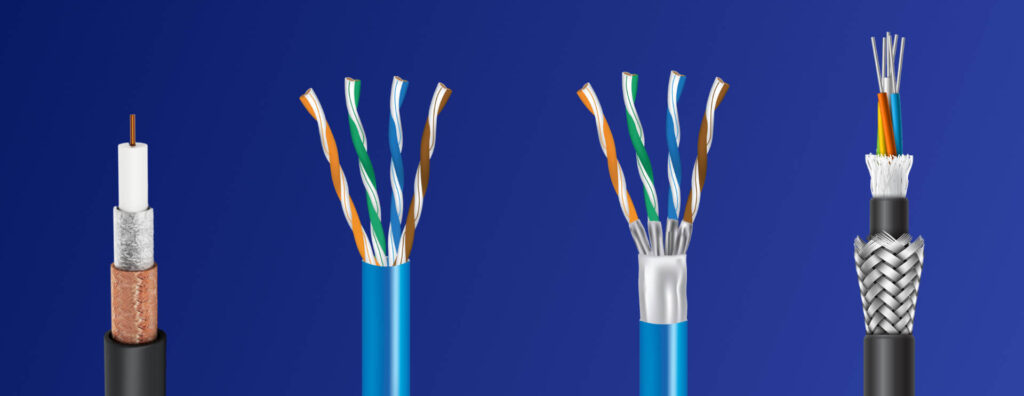
Compare the main network cable types — Cat5e, Cat6, Cat6A, shielded cables, and fiber optics — and understand speed, distance, PoE, connectivity, certification, and design-selection criteria.
Check it out!
The most widely used network cable types in modern infrastructure are balanced twisted-pair cables — mainly Cat5e, Cat6, and Cat6A — and fiber-optic cables. Coaxial cable still exists in specific and legacy applications, but it is not the predominant medium in modern structured Ethernet cabling.
The correct choice does not depend only on the speed printed on the package. Performance category and class, channel length, number of connections, electromagnetic interference, temperature, PoE, conductor type, installation environment, expected service life, and compatibility among cable, connectors, patch panels, and patch cords determine actual performance.
It is also important to distinguish concepts that are often mixed in everyday use: a network cable is the physical medium; Ethernet is a family of network technologies; Cat6/Cat6A are component categories for balanced cabling; and RJ45 is the popular name associated with the eight-position modular connector used in many copper networks. Infrastructure should be specified as a system, not as an isolated list of materials.
What are the main types of network cables?
In a corporate network, physical media can be grouped into three main families: balanced twisted pair, fiber optics, and, for specific cases, coaxial. Within twisted-pair cabling there are also different performance categories and shielding constructions.
| Type | Where it appears most often | Main characteristic | Design consideration |
| Cat5e | existing networks and less demanding applications | Class D, up to 100 MHz | evaluate service life before specifying in a new network |
| Cat6 | corporate and commercial networks | Class E, up to 250 MHz | 10GBASE-T should not be assumed at 100 m |
| Cat6A | higher-capacity and longer-life networks | Class EA, up to 500 MHz | larger diameter and greater pathway requirements |
| Cat7 / Cat7A | specific applications with compatible connectivity | Classes F and FA | ecosystem and connectors must be defined in the design |
| Category 8 | specialized high-frequency applications | up to 2,000 MHz | not an automatic replacement for conventional horizontal cabling |
| Multimode fiber | backbone and high-capacity links over controlled distances | OM1 through OM5 | compatibility with transceivers and optical budget |
| Single-mode fiber | campus, long distances, and high-capacity links | OS1/OS1a/OS2 depending on context | design must consider environment, connectivity, and application |
| Coaxial | RF, TV, legacy CFTV, and special systems | shielded concentric construction | not the typical basis of a modern structured Ethernet LAN |
ABNT NBR 14565:2019 recognizes balanced-cabling classes and categories ranging from legacy applications through Category 8. For fiber, the standard addresses optical-channel classes and multimode and single-mode fiber types. Selection should start from the applications the infrastructure must support and its expected service life, not from a generic rule that “the higher the category, the better.”
Are network cable, Ethernet cable, and RJ45 the same thing?
No. The three terms describe different things.
Network cable is a broad term for the physical medium used to carry communication signals. In a LAN, this normally means twisted pair or fiber optics.
Ethernet is a family of communication technologies standardized by IEEE 802.3. It can operate over different physical media. Therefore, “Ethernet cable” is an informal expression for the cable used in a given Ethernet implementation, not the name of a normative cable category.
RJ45 is the popular designation used for the eight-position modular connector found in twisted-pair networks. In technical documentation, it is more precise to describe the interface according to the applicable connection standard. ABNT NBR 14565 recognizes the T568A and T568B configurations for eight-position outlets in common balanced-cabling categories.
This distinction avoids ambiguous specifications. “RJ45 cable” does not specify category, shielding, channel class, conductor type, jacket, performance, application, or link configuration.
Cable category is not the same as channel class
A common mistake is to assume that installing Cat6 cable automatically creates a Cat6 system. Cabling-network performance depends on the complete channel or the permanent link, depending on the configuration being evaluated.
Category is associated with component requirements. Class describes the performance of the installed cabling. In NBR 14565, common associations include:
| Class | Associated category | Reference frequency |
| D | Category 5e | 100 MHz |
| E | Category 6 | 250 MHz |
| EA | Category 6A | 500 MHz |
| F | Category 7 | 600 MHz |
| FA | Category 7A | 1,000 MHz |
| Category 8 | Category 8 | 2,000 MHz |
If a channel mixes components of different categories, resulting performance is limited by the lowest-performing component. A Cat6A cable used with a Cat6 patch panel, for example, should not be treated as a Class EA channel simply because the horizontal cable has a higher category.
The same logic applies to termination and installation. Excessive pair untwisting, compression, improper bend radius, incompatible patch cords, poorly terminated connectors, and elevated temperature can degrade performance even when all components have the same nominal category.
Cat5e: where does it still make sense?
Cat5e is associated with Class D, specified up to 100 MHz. It remains widely present in existing installations and can support applications such as 1000BASE-T when the channel meets the applicable requirements.
In retrofit, maintenance, or expansion of an existing Cat5e network, retaining the category may be technically justified when:
- the application is clearly limited to 1 Gb/s or less;
- the infrastructure has remaining service life compatible with the investment;
- existing links are certified and documented;
- PoE, temperature, and cable density are compatible with the solution;
- there is no migration requirement for applications demanding higher performance.
In a new corporate design, however, specifying Cat5e simply because it meets the current application may create only small initial savings compared with the future cost of replacing fixed cabling. NBR 14565 establishes that horizontal cabling should support existing and emerging applications and have a minimum operational life of ten years. That expectation changes the economic analysis: cable selection should consider the infrastructure lifecycle, not only the switch installed today.
Cat6: the most common standard in corporate networks
Cat6 is associated with Class E and is specified up to 250 MHz. It is widely used in offices, schools, hospitals, stores, administrative buildings, IP CFTV, IP telephony, access control, and Wi-Fi networks.
For Gigabit Ethernet, Cat6 provides greater technical margin than Cat5e when the entire system is correctly designed and installed. This does not mean, however, that Cat6 and Cat6A are equivalent for 10 Gigabit Ethernet.
NBR 14565 itself notes that Class E channels may support 10GBASE-T under specific conditions and lengths, but recommends Class EA or better for new installations when that performance is part of the strategy. Therefore, simply stating that “Cat6 supports 10 Gb/s” without indicating channel limitations creates an inappropriate expectation.
Cat6 can be a rational choice when an organization requires 1 Gb/s, has a known expansion horizon, controlled budget, and a network architecture that does not require 10 Gb/s to the work area. The decision should be recorded in the design and coordinated with Wi-Fi, PoE, IP CFTV, and other connected systems.
Cat6A: when infrastructure needs longer life and 10 Gb/s
Cat6A is associated with Class EA, specified up to 500 MHz, and is the natural reference when the design must support 10GBASE-T over a channel of up to 100 m, provided all system requirements are met.
It tends to be appropriate in scenarios such as:
- high-capacity Wi-Fi access points;
- workstations or equipment that may migrate to multigigabit and 10 Gb/s;
- technical areas with higher traffic density;
- projects where future cabling replacement would be complex or costly;
- installations with a long expected service life;
- environments where additional performance margin is part of the risk strategy.
Cat6A also has physical consequences. Cables and components may occupy more space, have a larger bend radius, and require additional attention in conduits, cable trays, organizers, and racks. Therefore, migration from Cat6 to Cat6A should not occur only in the bill of materials; it must also be reflected in the sizing of cabling pathways and spaces.
The detailed comparison between these two categories is covered in the dedicated Cat6 vs. Cat6A article. Here, the purpose is to show where each category fits within the broader selection of cable types.
Cat7, Cat7A, and Category 8: why are they less common in offices?
Higher categories do not represent a mandatory upgrade sequence for every corporate network. Cat7 and Cat7A are associated with Classes F and FA, while Category 8 operates at an even higher frequency. Connectivity, applications, interfaces, and test criteria must be evaluated as a complete system.
In many commercial buildings, Cat6 and Cat6A dominate because the ecosystem of equipment, connectors, and Ethernet applications is broadly aligned with these categories. A design should not select Cat7, Cat7A, or Cat8 solely on the basis of nominal frequency or marketing claims.
The correct question is: which application must be supported, over what distance, for how long, and with which connectivity architecture? If the higher category does not solve a real requirement, it may only increase cost, installation complexity, and maintenance difficulty.
U/UTP, F/UTP, U/FTP, and S/FTP: understanding shielding
“UTP,” “FTP,” and “STP” are widely used commercial terms, but they can be ambiguous. The systematic nomenclature presented in NBR 14565 separately describes the overall cable construction and shielding of the pairs.
The X/YTP format identifies construction more precisely:
| Nomenclature | Simplified construction | Typical application |
| U/UTP | no overall shielding and individually unshielded pairs | offices and environments with controlled electromagnetic conditions |
| F/UTP | overall foil shield and individually unshielded pairs | locations where overall shielding is desired |
| U/FTP | no overall shield, with individually shielded pairs | applications requiring greater control of coupling between pairs |
| S/FTP | overall braid with foil-shielded pairs | more demanding electromagnetic environments and high-performance systems |
| SF/UTP | overall braid + foil, with individually unshielded pairs | specific constructions with dual overall shielding |
The nomenclature describes construction; by itself it does not guarantee category or performance. A shielded cable is not automatically Cat6A, and an unshielded cable is not automatically inferior for every application.
Shielded cable is not always better
Shielding should be treated as an engineering decision. NBR 14565 requires the components in a shielded channel to preserve shielding continuity. Terminations should maintain low impedance, and racks and cabinets are part of the grounding and bonding strategy.
Installing shielded cable with unshielded connectors, without electrical continuity, or without a coherent bonding system undermines part of the technical rationale for the choice. In industrial environments, the decision must also consider the electromagnetic environment, pathways, proximity to power circuits, grounding, and installation-specific requirements.
For a dedicated explanation of unshielded construction, the article on UTP cable retains that specific search intent.
Solid and stranded cable: why are they not interchangeable without analysis?
In horizontal cabling, the permanent portion normally uses cable appropriate for fixed installation, while patch cords use flexible construction to allow equipment connection and handling.
This difference has electrical consequences. NBR 14565 modeling considers that stranded cables used in patch cords may have higher insertion loss than horizontal cable. Therefore, the 90 m permanent-cable + 10 m patch-cord rule is a reference model, not authorization to assemble any 100 m channel in any configuration.
When total patch-cord length increases, the available length for horizontal cable may need to be reduced according to the configuration, category, and relative loss of the components. This is one reason why using long patch cords to compensate for poor distribution design is technically inappropriate.
It is also not advisable to fabricate patch cords indiscriminately from horizontal cable simply to “gain performance.” The assembly must meet application, connector, termination-method, and test requirements for the configuration being used.
90 m or 100 m: what is the distance limit for a network cable?
In balanced horizontal cabling, the two numbers refer to different quantities.
- 90 m is the reference physical limit for the permanent-link cable;
- 100 m is the physical limit for the complete horizontal channel;
- the channel includes patch cords and operational connections defined by the configuration;
- when patch cords exceed the reference model, the horizontal cable may need to be shortened;
- temperature above the reference condition may require additional length reduction.
In NBR 14565, implementation models consider 90 m of solid-conductor cable, 10 m of patch cords, and a defined number of connections. The standard also presents derating factors for operating temperatures above 20 °C; the effect differs between shielded and unshielded cables.
Therefore, the statement “network cable works up to 100 meters” is incomplete. The application must comply at the channel level, not only with the linear distance measured between two points.
The complete subsystem architecture is detailed in the article on Horizontal Cabling.
Temperature, bundles, and PoE can change cable selection
Power over Ethernet carries data and power over the same balanced cabling. This simplifies installation of IP cameras, access points, phones, sensors, and controllers, but introduces thermal and electrical criteria that do not exist in a link used only for data.
NBR 14565 draws attention to conductor gauge, electrical resistance, voltage drop, and operating temperature. In bundles with many energized cables, temperature rise can increase insertion loss and reduce the available channel margin.
When selecting cable for PoE, the design should consider:
- power required by the end device;
- planned PoE class and architecture;
- conductor resistance and applicable imbalance limits;
- ambient temperature;
- number of energized cables in the same bundle;
- pathway fill and ventilation;
- permitted cable and connector temperature;
- switch capacity and power budget;
- service life and potential future increases in power demand.
A cable that supports Gigabit Ethernet under favorable ambient conditions should not automatically be assumed suitable for a high-density PoE installation. The design must verify transmission and power delivery together.
Electrical sizing and power classes are discussed in greater depth in the Power over Ethernet article.
Fiber optics: when should copper be replaced by light?
Fiber optics should not be viewed simply as “a faster cable.” Its main difference is that it carries signals over an optical medium, providing high capacity and immunity to electromagnetic interference. This makes it particularly important for backbones, campus interconnections, building-to-building links, industrial environments, and routes where copper would be limited by distance or electrical context.
NBR 14565 classifies optical channels as OF-300, OF-500, and OF-2000 as length references and recognizes different multimode and single-mode fiber types. These class values do not eliminate the need to verify the application: connectors, splices, cable attenuation, and transceivers consume the optical loss budget.
Multimode fiber
OM1, OM2, OM3, OM4, and OM5 multimode fibers have different bandwidth and application characteristics. In current corporate networks, OM3 and OM4 frequently appear in high-capacity links over controlled distances, particularly within buildings and data centers.
Selection should not be based only on the OM designation. The following should be verified:
- Ethernet or Fibre Channel application;
- link length;
- wavelength;
- transceivers used;
- number of connections and splices;
- total permitted attenuation;
- redundancy architecture;
- expected evolution.
Single-mode fiber
Single-mode fiber is widely used in campus backbones, building interconnections, long-distance networks, and architectures that prioritize reach and capacity evolution. NBR 14565 addresses OS1, OS1a, and OS2 types in its optical-cabling context.
The design must coordinate fiber and cable type, indoor or outdoor environment, connectors, polish, transceivers, power budget, and operational strategy. Selecting “single-mode” without defining these elements is insufficient for procurement and acceptance.
Fiber does not carry PoE
Fiber optics do not conduct PoE electrical power through the optical medium itself. When a remote device depends on fiber and also requires power, power must be provided by electrical infrastructure or another suitable architecture. NBR 14565 makes this distinction when addressing wireless access points served by fiber.
For the complete optical system, the Fiber Optics Guide explores fibers, connectivity, links, and testing in greater depth.
Copper or fiber: how should the choice be made?
The choice does not need to be binary. Corporate networks normally combine both media: copper in horizontal access cabling and fiber in the backbone.
| Criterion | Twisted pair | Fiber optics |
| PoE power delivery | possible over the same cable | requires separate power |
| Typical horizontal distance | limited by the channel model | can significantly exceed copper depending on the application |
| Electromagnetic immunity | depends on balance, shielding, and installation | high immunity to EMI |
| Work-area termination | simple and widely deployed | depends on architecture and equipment |
| Backbone | possible in defined cases | generally preferred for capacity and distance |
| Building interconnection | requires rigorous electrical analysis | often favored because the medium provides electrical isolation |
| Future density/capacity | depends on category | high potential, subject to optical technology |
| Maintenance | widely established ecosystem | requires cleaning, inspection, and specific optical practices |
A building may, for example, use Cat6A horizontally for Wi-Fi and workstations, OM4 fiber between racks, and OS2 fiber between buildings. The design should create a coherent architecture rather than selecting one medium for every function.
Is coaxial cable still a network cable?
Historically, Ethernet networks used coaxial cable. Today it remains important in radio-frequency, television, antennas, analog CFTV, and special applications, but it is not the predominant medium in structured Ethernet cabling for commercial buildings.
In an infrastructure modernization project, finding coaxial cable does not necessarily mean it should be removed. The associated service should first be identified. A cable may still be required for RF or a legacy system even when the data network migrates to twisted pair and fiber.
The retrofit design should distinguish active infrastructure, abandoned cables, services still in operation, and pathways that may be reused. Removing or reusing cables without an inventory can affect systems that are not part of the data LAN.
How should a network cable type be selected in a design?
The choice among Cat6, Cat6A, fiber, and shielded cables should originate from application, distance, PoE, environmental, and lifecycle requirements — not only from the bill of materials.
Selection should start with the application and end in a verifiable specification. An engineering process can follow this sequence:
- Define applications and data rates: workstations, Wi-Fi, IP CFTV, telephony, automation, servers, and future requirements.
- Map distances: work area, building backbone, campus, and building-to-building links.
- Evaluate PoE: power, device count, bundle density, and switch capacity.
- Characterize the environment: temperature, humidity, interference, exposure, pathways, and mechanical requirements.
- Define medium and performance: copper or fiber, class, category, optical type, and connectivity.
- Size pathways and spaces: external cable diameter, fill, bend radius, access, and expansion.
- Specify compatible components: cable, outlet, patch panel, patch cord, DIO, and connectors.
- Plan identification and administration: codes, ports, racks, routes, and change control.
- Define testing and acceptance: test configuration, limits, instruments, reports, and traceability.
- Record the decision: design narrative, drawings, details, cable schedule, and technical-equivalence criteria.
This approach prevents the supplier from turning cable purchasing into an isolated decision. The Structured Cabling Design should establish performance and compliance evidence before procurement.
The installation environment can matter more than category
The same Cat6 cable can behave differently depending on the environment and installation method. Temperature, humidity, chemicals, mechanical stress, vibration, dust, electromagnetic interference, and outdoor exposure change the overall requirements.
In offices, U/UTP may be fully appropriate when pathways, separation, and environmental conditions are controlled. In an industrial facility, the solution may require shielding, suitable enclosures, greater mechanical protection, fiber optics, or a combination of these strategies.
NBR 16869-1 reinforces that installation planning and quality must consider environmental requirements and interfaces with other disciplines. Therefore, “shielded Cat6A” is not a universal answer for harsh environments. The medium, pathway, protection, and termination must be evaluated together.
Pathways and spaces must be sized for the selected cable
Changing category or construction changes occupied space. Cat6A cables and shielded versions can have significantly different outside diameters from simpler solutions. The impact appears in:
- conduits;
- cable trays;
- ladder trays;
- shafts;
- hooks and supports;
- rack entries;
- horizontal and vertical cable managers;
- boxes and consolidation points;
- corporate furniture.
ABNT NBR 16415 addresses pathway and space sizing and uses fill based on the actual area of cables and infrastructure, rather than generic tables independent of product diameter. Therefore, defining the cable after every conduit has already been sized can lead to rework.
The article on Horizontal Cabling Pathways and Infrastructure details fill, conduits, cable trays, boxes, bends, and expansion.
Patch panel, outlet, and patch cord are part of the selection
The horizontal cable is only one component. The channel includes connectivity and cords, and its performance depends on the complete assembly.
In a Cat6A specification, for example, the following should be coordinated:
- horizontal cable;
- outlets and connectors;
- patch panels;
- equipment patch cords;
- work-area patch cords;
- equipment connectors and interfaces;
- termination practices;
- test configuration.
NBR 14565 establishes backward compatibility for connectivity of different categories, but the assembly performance is limited by the lower category. This means components that “fit” do not necessarily deliver the intended class.
For termination of Category 5e and higher, the standard also limits pair untwisting to 13 mm. This detail illustrates how high-frequency performance depends on workmanship: buying the correct product is not enough; its performance must be preserved during installation.
The article on Structured Cabling Components explores the relationship among cables, patch panels, racks, DIOs, and other elements in greater depth.
T568A or T568B: what changes in the network cable?
T568A and T568B are termination configurations recognized by NBR 14565 for eight-position modular outlets. Both can provide proper connectivity when used consistently.
The main point is not to choose a “faster” sequence. Performance category is not determined by whether T568A or T568B is selected. The critical requirement is to maintain the configuration defined in the design and consistency between the two ends of the link.
Mixing terminations without control may preserve some electrical continuity while still compromising proper connectivity. The adopted standard should be documented in drawings, identification, and installation procedures.
Which cable should be used for corporate Wi-Fi?
Modern access points place two pressures on cabling: increasing capacity requirements and PoE power delivery. NBR 14565 contains a specific section for wireless-access-point infrastructure and recommends, for new implementations, Class EA/Category 6A for balanced cabling and OM3 when the solution is optical.
The standard also recommends that each coverage area be served by at least two telecommunications outlets to increase flexibility and capacity for future evolution. Outlet positions must be coordinated with the radio-frequency design; cabling should not arbitrarily determine where the access point will be installed.
The design should verify:
- number of radios and access-point capacity;
- 1, 2.5, 5, or 10 Gb/s uplink according to the equipment;
- PoE class and required power;
- ceiling outlet locations;
- channel length;
- possibility of redundancy or a second outlet;
- user density and system evolution.
For a new environment, installing cabling only for the current generation of access points can bring forward obsolescence of the passive infrastructure.
Which cable should be used for IP cameras and access control?
IP CFTV and access control frequently use Ethernet and PoE but have their own operational characteristics. Cameras may be installed outdoors, in parking areas, along perimeters, and in locations exposed to surges, moisture, and potential differences. Controllers and readers may integrate with corporate networks and security systems that have high availability requirements.
Cable selection should consider:
- indoor or outdoor environment;
- distance to the distributor;
- PoE power;
- surge protection where applicable;
- grounding and bonding;
- routes shared with power circuits;
- system availability;
- logical and physical segregation defined by the design;
- maintenance and accessibility.
For building interconnections or areas subject to complex electrical conditions, fiber optics may be more appropriate for the backbone, leaving copper only for the final segment where PoE is required.
Which cable should be used in the backbone?
Backbone is not synonymous with fiber, but fiber optics are often the preferred solution because of the combination of distance, capacity, density, and electromagnetic immunity.
Sizing should start from aggregate traffic, redundancy, fiber count, transceiver speed, spare capacity, topology, and expected growth. In a campus, route accessibility also matters: infrastructure that is difficult to replace should receive greater expansion margin.
NBR 14565 distinguishes campus backbone from building backbone. The campus layer may require a longer-life solution precisely because external routes are more difficult and expensive to modify.
The article on Fiber Optic Backbone addresses this architecture specifically and should remain the owner of that search intent.
How can cables be specified without tying the design to a brand?
A good specification describes measurable requirements. Instead of simply naming a commercial model, the design should state the performance and conditions the component must meet.
For balanced cables, the specification may include, as applicable:
- intended category and channel class;
- compatible nominal impedance;
- shielding construction;
- horizontal, backbone, or cord application;
- conductor characteristics required by the design;
- temperature range and environment;
- outside diameter for pathway sizing;
- identification requirements;
- compatibility with connectivity and patch panels;
- test and documentation criteria.
For fiber optics:
- OM or OS type;
- cable construction and installation environment;
- fiber count;
- connectivity and polish;
- attenuation and optical budget;
- bend radius and mechanical requirements;
- application and distance;
- identification and polarity strategy;
- planned loss and characterization tests.
This format enables technical bid equalization without reducing equivalence to “looks similar.” The supplier must demonstrate that the offered product meets the established requirements.
Procurement: price per meter is not the total system cost
Comparing only price per meter can distort the decision. Cabling cost includes connectivity, infrastructure, labor, rack occupancy, testing, documentation, and the possibility of future replacement.
A cheaper cable may require another intervention before the end of the building’s service life. On the other hand, specifying a higher category without an application or without the physical capacity to install it also destroys value.
Technical bid equalization should compare at least:
| Aspect | Verification question |
| Performance | does it meet the specified class/category and application? |
| System | are connectors, panels, and cords compatible? |
| Environment | does construction and operating range suit the location? |
| Installation | do diameter, bend radius, and pulling requirements fit the existing pathways? |
| PoE | do resistance and thermal conditions support the planned load? |
| Evidence | are datasheets, certificates, and traceability available? |
| Acceptance | does the supplier accept the tests and criteria defined in the design? |
| Lifecycle | does the solution support planned growth and maintenance? |
The goal of technical procurement is to purchase a demonstrable infrastructure capability, not merely an SKU.
Installation can destroy the performance of a good cable
Installation practices are part of performance. NBR 14565 emphasizes protection against mechanical tension, sharp surfaces, excessive compression, improper bending, and inadequate preparation for termination.
Frequent failures include:
- exceeding bend radius;
- crushing bundles with excessively tight ties;
- applying improper pulling force;
- removing more jacket than necessary;
- untwisting pairs excessively;
- making improvised splices in a horizontal link;
- mixing categories without control;
- using connectors incompatible with cable diameter or construction;
- leaving shielding without continuity;
- routing cables through unsuitable infrastructure;
- failing to respect the product’s environmental conditions.
These failures may not be visible in a simple continuity test. That is why a network that “pings” or “lights the switch port” is not necessarily certified for the contracted category.
Certification: the cable must be tested as an installed system
Certification should verify link or channel performance in the configuration defined by the design. For balanced cabling, NBR 14565 references test procedures and establishes acceptance parameters that include, depending on the configuration:
- wire mapping;
- continuity and shielding, where applicable;
- length;
- insertion loss;
- return loss;
- NEXT and PS NEXT;
- derived relationships such as ACR and ACR-F;
- DC loop resistance;
- propagation delay;
- propagation-delay skew.
The ABNT NBR 16869 series expands the treatment of installation quality and testing. Part 1 integrates planning, documentation, inspection, and acceptance; Part 2 specifically addresses optical-cabling testing; and Part 3 covers special configurations such as MPTL and direct connection.
For fiber, optical loss, continuity, polarity, and characterization must be planned according to the architecture and acceptance criteria. Reports should be traceable to the actual link identifier and, where applicable, preserve the instrument’s native files.
A continuity test does not replace certification. This distinction is essential in contracts, warranties, and technical acceptance.
How should network cables be handled in retrofit projects?
An existing network should not be replaced simply because it was installed with an older category. The first step is to determine what exists and its condition.
An audit can document:
- category and manufacturer of cables and components;
- topology, origin, and destination of links;
- channel length and configuration;
- physical condition of racks, patch panels, DIOs, and pathways;
- available identification and documentation;
- port utilization rate;
- current and future applications;
- PoE and expected loads;
- existing certification results;
- physical capacity for expansion or replacement.
Based on these findings, links can be classified for maintenance, recertification, correction, reuse, or replacement. In many projects, part of the cabling can remain in service while backbones, critical areas, or high-capacity points are selectively modernized.
This approach reduces waste without freezing the infrastructure in an unsuitable technology.
Quick matrix: which cable type should be selected?
The table below is an initial guide and does not replace the design.
| Situation | Solution normally evaluated first | What can change the decision |
| new office network | Cat6 or Cat6A | service-life horizon, Wi-Fi, 10 Gb/s, and PoE |
| high-capacity Wi-Fi | Cat6A | equipment, uplink, power, and architecture |
| indoor IP CFTV | Cat6/Cat6A according to design | PoE, density, distance, and environment |
| environment with relevant EMI | shielded solution or fiber | grounding, routes, MICE, and application |
| backbone between racks | fiber optics | distance, capacity, transceivers, and redundancy |
| building interconnection | fiber optics | campus architecture and availability requirements |
| existing Cat5e network | evaluate and certify before replacement | future application and system condition |
| data center | fiber and/or high-category copper | architecture, distance, density, and active platform |
| remote point with PoE | copper within channel limits | distance, power, and protection |
| long distance without power required on the same medium | fiber | optical budget and equipment |
The matrix helps formulate initial hypotheses. The final decision should result from requirements, site survey, and design calculations.
Common mistakes when selecting network cable types
Selecting only by advertised speed
“10 Gb/s” does not describe length, connections, temperature, application, or test conditions. The data rate is the result of a channel that complies with the applicable standard.
Treating RJ45 as a category
RJ45 does not define Cat5e, Cat6, or Cat6A. Connectivity must be specified together with category and termination configuration.
Using “STP” without defining the construction
The term can be interpreted in different ways. U/UTP, F/UTP, U/FTP, S/FTP, and other notations describe more precisely where shielding is present.
Buying Cat6A without resizing the infrastructure
Increased diameter and bend radius can make conduits, cable trays, and organizers unsuitable.
Using shielded cable without shielding continuity
A shielded channel requires coherent components and terminations, plus grounding and bonding according to the design.
Ignoring patch cords
Patch cords are part of the channel and may have greater loss than horizontal cable. Excessive lengths reduce margin and may require shortening the permanent segment.
Selecting fiber without an optical budget
The number of connectors, splices, link length, and transceivers must fit within the application’s loss budget.
Accepting continuity alone
Continuity indicates basic electrical connection; it does not demonstrate NEXT, return loss, insertion loss, or other category requirements.
Failing to plan for expansion
Passive infrastructure often remains in operation longer than switches, access points, and servers. Designing it only for immediate requirements brings forward future rework.
Checklist for specification and acceptance
Before procuring or accepting network-cabling infrastructure, verify:
- current and planned applications are defined;
- physical medium is selected according to requirements;
- class and category are identified;
- shielding type is specified without ambiguous terminology;
- distances and channel configurations are verified;
- patch cords are included in calculations;
- temperature and PoE are analyzed;
- pathways are sized using actual cable diameter;
- connectors, patch panels, and outlets are compatible;
- fiber is defined by type, connectivity, and optical budget;
- termination standard is documented;
- identification and administration are planned;
- tests are defined before installation;
- test instruments and configurations are compatible;
- failure and retest criteria are defined;
- reports are traceable to installed outlets and links;
- As Built documentation and port matrix are included in delivery;
- technical equivalence is based on performance, not only brand or price.
Final considerations
There is no single “best network cable” for every scenario. Cat5e, Cat6, Cat6A, shielded cables, and fiber optics occupy different positions within an architecture. The correct selection combines application, distance, environment, PoE, future capacity, pathways, connectivity, testing, and lifecycle cost.
For new installations, the greatest risk is treating cable as a commodity and leaving category, shielding, route, or connectivity decisions to the installer during construction. For existing networks, the opposite risk is replacing everything without diagnosis. In both cases, design, survey, specification, and acceptance criteria turn a material purchase into a verifiable engineering decision.
Certification turns the specified category into objective performance evidence. Acceptance should be planned before installation, with configuration, limits, instruments, and traceability defined.
Technical references
[1] ASSOCIAÇÃO BRASILEIRA DE NORMAS TÉCNICAS. ABNT NBR 14565:2019 — Cabeamento estruturado para edifícios comerciais. Rio de Janeiro: ABNT, 2019. Available at: https://www.abntcatalogo.com.br/.
[2] ASSOCIAÇÃO BRASILEIRA DE NORMAS TÉCNICAS. ABNT NBR 16415 — Caminhos e espaços para cabeamento estruturado. Rio de Janeiro: ABNT. Available at: https://www.abntcatalogo.com.br/.
[3] ASSOCIAÇÃO BRASILEIRA DE NORMAS TÉCNICAS. ABNT NBR 16869-1 — Cabeamento estruturado — Parte 1: Requisitos para planejamento. Rio de Janeiro: ABNT. Available at: https://www.abntcatalogo.com.br/.
[4] ASSOCIAÇÃO BRASILEIRA DE NORMAS TÉCNICAS. ABNT NBR 16869-2 — Cabeamento estruturado — Parte 2: Ensaio do cabeamento óptico. Rio de Janeiro: ABNT. Available at: https://www.abntcatalogo.com.br/.
[5] ASSOCIAÇÃO BRASILEIRA DE NORMAS TÉCNICAS. ABNT NBR 16869-3 — Cabeamento estruturado — Parte 3: Enlace ponto a ponto, MPTL e conexão direta. Rio de Janeiro: ABNT. Available at: https://www.abntcatalogo.com.br/.
[6] ASSOCIAÇÃO BRASILEIRA DE NORMAS TÉCNICAS. ABNT NBR 14703 — Cabos de telemática de 100 Ω para redes internas estruturadas — Especificação. Rio de Janeiro: ABNT. Available at: https://www.abntcatalogo.com.br/.
[7] ISO/IEC. ISO/IEC 11801-1 — Information technology — Generic cabling for customer premises — Part 1: General requirements. Available at: https://www.iso.org/standard/66182.html.
[8] IEEE. IEEE 802.3 — Ethernet. Available at: https://standards.ieee.org/ieee/802.3/.
Frequently asked questions
The main types are balanced twisted-pair cables such as Cat5e, Cat6, and Cat6A, and fiber-optic cables. Coaxial remains in specific and legacy applications.
A network cable is the physical medium. Ethernet is a family of communication technologies. An Ethernet implementation may use twisted pair or fiber depending on the application.
No. RJ45 is the popular designation used for the eight-position modular interface found in many copper networks. Cat5e, Cat6, and Cat6A are performance categories, not types of RJ45.
It depends on the application and lifecycle. Cat5e may remain suitable in existing networks; Cat6 is common in corporate networks; Cat6A is appropriate when 10GBASE-T over up to 100 m, greater technical margin, or long service life are requirements.
It can support 10GBASE-T under defined conditions and lengths, but it should not be assumed at 100 m. For new installations that require 10 Gb/s over a channel of up to 100 m, Class EA/Cat6A is the appropriate reference.
No. Shielding is an engineering decision. A shielded channel requires compatible components, shielding continuity, proper termination, and bonding. In a controlled environment, U/UTP can be fully appropriate.
In balanced horizontal cabling, the permanent-link cable has a reference maximum of 90 m and the complete channel 100 m. Patch cords, temperature, and configuration may require shortening the permanent segment.
Fiber is especially appropriate for backbones, long distances, building interconnections, high capacity, and environments with electromagnetic interference. Copper is highly useful for horizontal access and when PoE must reach the equipment.
NBR 14565 recommends, for wireless access-point infrastructure, at least Class EA/Category 6A for balanced cabling and OM3 for optical cabling, subject to design and equipment requirements.
In professional installations, link or channel performance should be verified according to the criteria defined in the design and applicable standards. A continuity test does not demonstrate the system category.
Complementary technical materials
Related solutions
Related services
Main content on this topic
- Complete Guide to Structured Cabling
- NBR 14565: Structured Cabling for Commercial Buildings
- Structured Cabling Components
- Horizontal Cabling
