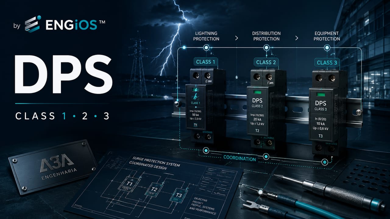
In-depth technical guide to Class 1, Class 2 and Class 3 SPDs: Iimp, In, Uoc, applications, LPS, S1-S4 sources, Up/f, Uw, coordination and selection criteria.
Check it out!
Class 1, Class 2 and Class 3 SPDs are not defined solely by the point in the distribution system where they are installed. The classification is linked to the tests to which the device has been subjected, the quantities that characterize those tests and the type of stress the SPD must withstand within the surge-protection architecture.
In ABNT NBR IEC 61643-11, Class I tests are characterized by impulse current Iimp; Class II tests by nominal discharge current In; and Class III tests by the open-circuit voltage Uoc of the combination-wave generator. The practical consequence is important: comparing the classes merely as “strong, medium and fine” oversimplifies the problem and can lead to incorrect selection.
Correct application depends on the origin of surges, the presence of an LPS, the share of current expected at the point, the maximum continuous operating voltage Uc, the voltage protection level Up, the equipment impulse withstand voltage Uw, the effective level Up/f, coordination between stages and short-circuit conditions. The class is one part of the specification, not the entire specification.
In industrial installations, corporate buildings, data centers, automation, telecommunications and other environments with sensitive electronic systems, the objective is not simply to distribute classes among panels. The objective is to create a protection chain capable of conducting the expected energy and reducing overvoltage to levels compatible with the protected equipment.
What do Class 1, Class 2 and Class 3 mean in an SPD?
The classification should be read as a test classification. It indicates which forms of stress were used to verify SPD behavior and which quantities are used to characterize its performance.
| Class | Main quantity | Type of stress | What the class demonstrates |
| Class I | Iimp | impulse current with peak, charge and specific-energy requirements | capability to withstand stresses associated with portions of lightning current |
| Class II | In | 8/20 µs impulse current | performance under shorter-duration surges, typical of induced surges and conducted transients |
| Class III | Uoc | 1.2/50 µs and 8/20 µs combination-wave generator | performance as a complementary stage, normally under lower-energy conditions at the protected point |
The introduction to ABNT NBR IEC 61643-11 itself distinguishes the three groups. Class I tests seek to simulate conducted partial lightning currents. Class II and III tests use shorter-duration impulses.
This explains why the commercial equivalence “Class 1 = service entrance, Class 2 = distribution board, Class 3 = outlet” is only a didactic approximation. The location may match this sequence in many installations, but actual selection depends on the source of damage, current distribution and SPM coordination.
For an overview of the device before examining the classes in depth, see SPD: what it is, what it is used for, classes, sizing and installation.
Test class is not the same as protection level
Another common mistake is to interpret Classes I, II and III as if the class directly determined how low the voltage reaching the equipment would be. This mixes energy capability with voltage limitation.
The parameter directly related to limitation is Up, the voltage protection level declared by the manufacturer. Actual performance in the circuit, however, must consider Up/f, which also incorporates the voltage drop in conductors and components of the SPD branch.
A Class I SPD may be capable of withstanding high energy while presenting a Up value higher than desirable for a sensitive electronic load. A downstream Class II or III SPD may then be necessary to reduce the effective voltage level. The correct logic is to coordinate withstood energy + limited voltage + location + connection.
Class 1 SPD: when impulse current Iimp is decisive
The Class 1 SPD, also identified in the market as T1 or Type 1, is tested for a stress represented by Iimp. This quantity is not merely a peak value in kiloamperes. Its definition involves peak value, charge transfer Q and specific energy W/R over a specified time.
This difference is essential to avoid directly comparing Iimp with In or Imax as though all were merely “SPD kA”. An impulse current associated with direct lightning has different energy content from an 8/20 µs current with the same peak amplitude.
Relationship between Class I and direct lightning
ABNT NBR 5419-4:2026 establishes in Annex C that when the structure requires an LPS, or when other sources of impulse current are identified in the installation, SPDs tested to Class I must be used at the corresponding points.
The logic derives from the sources of damage:
S1: direct lightning flash to the structure;S3: direct lightning flash to a line connected to the structure.
In these scenarios, part of the lightning current may reach power and signal lines. The SPD at the boundary must be selected for the portion of current that can actually pass through it.
Therefore, the statement “if there is a lightning protection system, use Class 1” is not entirely wrong, but it is insufficient. Engineering must determine where the current enters, how it divides and what Iimp is required in that protection mode.
Does the installation have an LPS, multiple metallic entrances or critical equipment?
In these cases, class selection should be part of a surge-protection architecture, defining boundaries, expected currents, Up, Up/f, grounding and coordination. See the Surge Protection Measures (SPM) Design service.
Iimp should not be selected solely from a product table
NBR 5419-4:2026 shows that the current expected in an SPD depends on factors such as:
- Lightning Protection Level;
- SPD installation point;
- number of metallic lines connected to the structure;
- current distribution between grounding and metallic services;
- grounding system;
- path impedance;
- interconnection with other structures;
- waveform and transferred charge.
Annex D even presents examples in which the current share in each conductor varies greatly according to the number of metallic services available to divide the discharge. This demonstrates why “using 12.5 kA because it is common in the market” does not replace system analysis.
10/350 µs and correct interpretation of Class I
Class I is commonly associated automatically with the 10/350 µs waveform. In lightning-protection practice, this waveform is an important reference for representing longer-duration currents with higher energy content. However, ABNT NBR IEC 61643-11 defines Iimp by peak, charge and specific energy, not merely by the name of a waveform.
The decisive information is to verify the declared values and product test regime, rather than simply looking for the “10/350” marking in the catalog.
Where is a Class 1 SPD usually installed?
The first opportunity to divert a portion of impulse current is normally close to the point where the line enters the structure and to the main equipotential bonding. For this reason, a Class I SPD frequently appears:
- at the power service entrance;
- in the main low-voltage switchboard near the entrance;
- at the boundary between an external and internal LPZ;
- in panels receiving lines exposed to direct currents;
- at metallic interconnections between structures, according to the SPM analysis.
NBR 5410 establishes specific criteria for locating SPDs at the service entrance or main distribution board, while NBR 5419-4 extends this logic to LPZs, SPM and internal systems.
However, it is not correct to conclude that every SPD installed in the main switchboard must be Class I. If the relevant source of damage is only induction or switching and no direct impulse current is expected at that point, a Class II SPD may be sufficient.
Class 2 SPD: the role of In and the 8/20 µs waveform
The Class 2 or T2 SPD is characterized by the nominal discharge current In, whose waveform is 8/20 µs. It is widely used in distribution boards and internal protection stages against induced or conducted surges.
NBR 5419-4:2026 establishes that, for protection only against induced-voltage effects or switching overvoltages, SPDs tested to Class II must be installed.
The most directly associated sources of damage are:
S2: lightning flash near the structure;S4: lightning flash near connected lines.
In these cases, the SPD is not necessarily conducting the same share of current associated with a direct strike, but it must withstand the expected induced surges.
What In actually means
In is the peak value of the 8/20 µs current used in Class II tests. The value is important because it participates in repetitive-performance verification and determination of residual voltage under standardized conditions.
However, In should not be confused with:
Imax, the maximum 8/20 discharge current declared by the manufacturer;Iimp, the Class I impulse current;ISCCR, the capability related to the network short-circuit current;- the rated current of a backup circuit breaker.
This distinction is discussed in more detail in 20 kA, 40 kA, 45 kA or 60 kA SPDs.
Where is a Class 2 SPD applied?
Class II is extremely common in main distribution boards where no direct current requires Class I, secondary distribution boards, industrial panels, automation panels, technical-room supplies, sensitive-equipment circuits and stages downstream of Class I SPDs.
But location is not sufficient. A Class II device must be evaluated for Uc, Up, In, Imax, ISCCR, TOV, protection mode, coordination and distance to the load.
A 40 kA Class II SPD may be excellent in one installation and unsuitable in another. Higher discharge current may only increase energy capability or expected service life; it does not guarantee that Up is suitable for the equipment.
Class 3 SPD: complementary protection and combination wave
The Class 3 or T3 SPD is tested using a combination-wave generator. The characteristic parameter is Uoc, the generator open-circuit voltage, associated with a 1.2/50 µs voltage waveform and an 8/20 µs short-circuit current.
This class is normally used as a complementary stage close to sensitive equipment when upstream protection is insufficient to guarantee the required level at the load terminals.
Class III does not replace the preceding stages
A Class III SPD was not designed to indiscriminately receive the same energy as an entrance device. If the installation is exposed to more severe currents, that energy must be reduced by upstream stages before reaching the fine-protection device.
Therefore, Class III must be analyzed within a coordinated SPD system.
When an additional SPD near the equipment is necessary
NBR 5419-4:2026 establishes criteria based on Up/f, Uw and distance.
When the length between the SPD and equipment is negligible, a basic condition is Up/f ≤ Uw. For sections up to 10 m, the standard introduces more conservative margins, such as Up/f ≤ 0.8 Uw; when system failure is critical, the condition may reach Up/f ≤ 0.5 Uw.
For distances greater than 10 m, additional measures may be required, such as another SPD near the equipment, two-port SPDs, shielded cabling, joint routing of live conductors and PE, and reduction of loop area.
This provides the technical justification for a third protection stage. It is not the class alone that determines the need; it is the effective protection level reaching the load.
Is critical equipment far from the protected distribution board?
Distance, routing and inductive voltage drop can increase Up/f even when the SPD was correctly selected from the catalog. SPM engineering verifies the need for additional stages, shielding, coordination and protection close to the load.
Can Classes 1, 2 and 3 exist in the same system?
Yes. A coordinated system may use different classes in sequence, provided there is energy and voltage compatibility between the devices.
A conceptual arrangement may be:
1. Class I at the entrance to conduct a portion of impulse current; 2. Class II at an intermediate board to reduce residual surges; 3. Class III close to the load when equipment withstand capability requires an additional stage.
This sequence, however, is not a universal recipe. In an installation without direct impulse current, the first stage may be Class II. In another, a combined T1+T2 SPD may fulfill more than one function. In equipment with built-in protection, coordination must consider the internal SPD.
The article SPD Coordination: cascade, energy, Up/f and system protection specifically addresses this interface.
Combined T1+T2 and T2+T3 SPDs
The market offers SPDs classified for more than one test class. A T1+T2 device, for example, may have declared performance for both Iimp and In.
This does not mean it automatically eliminates the need for every other stage. The decision depends on Up and Up/f, distance to the equipment, required energy capability, critical loads, coordination with downstream SPDs and signal lines connected to the same equipment.
A T1+T2 device can be excellent at the entrance and still require a T2 or T3 close to a distant, sensitive load.
Class, voltage protection and integration with the LPS
Uc is the maximum RMS voltage that can be continuously applied to the SPD protection mode. The class does not define Uc.
Class I, II or III SPDs can have different maximum continuous operating voltages. Selection must consider nominal system voltage, connection mode, TN, TT or IT system, supply tolerance, temporary overvoltages and phase-neutral, phase-PE, neutral-PE or phase-phase position.
Therefore, choosing “Class II 275 V” without checking the network may be just as unsuitable as choosing the wrong class.
See 175 V or 275 V SPD: difference, Uc, system voltage and how to choose for the specific voltage analysis.
How class relates to Up and Uw
Up represents the declared voltage protection level. Uw represents equipment impulse withstand voltage.
The objective is for the effective overvoltage reaching the terminals to remain below the load’s withstand capability. However, the actual level is affected by inductive voltage drop in SPD conductors, branch length, backup devices, connections, wave propagation, induction in the circuit and distance to the equipment.
This is why NBR 5419-4 uses the Up/f concept. A perfectly “ordered” class system may fail if SPDs are installed with long conductors or improper routing.
How class relates to the LPS
The external LPS handles interception, conduction and dissipation of direct lightning current. Protection of internal electrical and electronic systems is handled by SPM.
When the analysis indicates direct current flowing through lines, Class I SPDs are used at the relevant boundary. But the LPS does not automatically make every internal distribution board a Class I point.
Current divides, energy is reduced and the internal architecture then requires coordination with Classes II and III as needed.
Therefore, Surge Protection Measures (SPM) Design should be integrated with the LPS Design when both systems coexist.
How to select the SPD class: an engineering method
The class should emerge as a consequence of characterizing the installation and expected stress, not as an isolated catalog choice. A practical design sequence is:
| Step | Engineering verification |
|---|---|
| 1. Characterize the installation | Voltage, TN/TT/IT, source, boards, distances, LPS, external and signal lines, critical equipment and short-circuit current. |
| 2. Identify surge sources | Differentiate S1/S3, associated with direct currents, from S2/S4, induction and switching overvoltages. |
| 3. Determine expected current | Define Iimp when Class I is required and suitable In for Class II, considering location and current division. |
| 4. Select Uc and verify TOV | Confirm continuous voltage by protection mode and possible temporary overvoltages. |
| 5. Verify Up, Up/f and Uw | Compare the effective protection level with equipment withstand capability, including connection lengths and geometry. |
| 6. Define additional stages | Evaluate downstream Class II or III where distance, criticality or load withstand capability requires additional protection. |
| 7. Coordinate energetically | Use manufacturer data and applicable criteria to ensure compatibility among cascaded devices. |
| 8. Verify short-circuit and backup protection | Confirm ISCCR, disconnectors, backup protection and prospective current. The interface is discussed further in SPD and Circuit Breaker. |
Examples and application decisions
Consider a building with an LPS, a main low-voltage switchboard at the entrance, floor distribution boards and IT equipment tens of meters away.
At the main switchboard, engineering identifies the possibility of a share of direct current. The entrance stage must be compatible with Class I and with Iimp calculated or defined according to the normative assumptions.
At the floor distribution boards, the available energy is already lower, but residual and induced surges are still present. Class II SPDs may be used, provided they are coordinated with the first stage.
At the supply to a distant technical room, Up/f at the load terminal is evaluated. If the level does not meet the equipment Uw, an additional stage close to the load may be necessary, potentially Class III.
The correct reasoning is: threat → current → residual voltage → distance → withstand capability → coordination. The classes appear as a consequence of this process.
Conceptual example: installation without an external LPS
A building may not require an external LPS and still need surge protection.
If the analysis indicates that no direct S1/S3 currents are involved at the entrance point, but induced and switching surges exist, a Class II SPD may be the first stage.
This demonstrates that “Class I always at the entrance” is not a universal rule.
Conceptual example: critical equipment more than 10 m from the protected board
Suppose a Class II SPD is installed in the board and presents a Up compatible with the load. The equipment, however, is 25 m away.
Surge propagation, induction and circuit geometry can increase overvoltage at the load terminal. NBR 5419-4 provides additional measures for distances greater than 10 m.
In this case, engineering may evaluate an additional SPD near the equipment, Class III or another Class II depending on available energy, two-port SPDs, shielding and routing changes.
The need arises from effective performance, not from a decorative class rule.
Class I or Class II in the main board?
The answer depends on the source of damage and expected current.
The technical question is: can a portion of direct lightning current flow through this point?
If yes, Class I should be considered. If not, and the stress is induced or caused by switching, Class II may be sufficient.
The existence of overhead lines, LPS, structure and grounding, connected metallic services, risk analysis, current distribution, BEP location and connection arrangement should also be verified.
Class II or Class III near the load?
The choice depends on how much energy can still reach the point and what effective voltage level must be achieved.
A Class III SPD is not automatically “better” for electronic equipment. If the available energy exceeds its capability, it must be preceded by suitable stages.
In many cases, a low-Up Class II SPD that is correctly coordinated may be used close to the load. In others, Class III is the appropriate solution. Manufacturer documentation and coordination must be verified.
Common mistakes when choosing the class
| Mistake | Why it compromises the specification |
|---|---|
| Choosing the class only by panel location | Location is a consequence of the architecture and surge source; it does not replace analysis of stress at the point. |
| Treating Class I as “more protective” than Class II | Class indicates the test regime. For the load, Up, Up/f and Uw may be more decisive. |
| Directly comparing Iimp with In | They are quantities associated with different test regimes and do not form a linear kA scale. |
| Installing Class III directly at a high-energy point | This may subject the device to stress above the regime for which it was designed. |
| Using Class II where direct current exists without verifying Iimp | This may result in energy undersizing of the first stage. |
| Ignoring Uc and TOV | The class may be correct while maximum continuous operating voltage is unsuitable for the network. |
| Ignoring Up/f and physical installation | Long conductors, routing and connections can raise the effective voltage above the load’s withstand capability. |
| Mixing manufacturers without coordination data | Energy compatibility between stages is no longer demonstrated. |
| Ignoring signal lines | The equipment may receive an overvoltage through another metallic port even with the power supply protected. |
Connection arrangements, grounding and physical installation
A multipole SPD has more than one protection mode or a combination of interconnected devices. In multipole applications, it is also important to verify the total discharge current ITotal when declared.
NBR IEC 61643-11 highlights the relevance of ITotal, especially for Class I SPDs used for lightning-related equipotential bonding, because multiple modes may conduct simultaneously.
This is particularly important in three-phase systems with a neutral, where simply reading the per-pole value may not represent the full stress on the assembly.
Class and TN, TT and IT systems
The class does not define the connection. The grounding system determines which modes must be protected and which voltages appear between terminals.
Under NBR 5410, additional SPDs in TN-S, TT with neutral and IT with neutral may be configured, depending on the arrangement, between phases and PE and between N-PE, or between phases and neutral and between neutral and PE. In TN-C and circuits without neutral, the configuration changes.
Therefore, a “Class II 275 V SPD” is not a complete solution without defining where its poles will be connected.
The role of conductor length
NBR 5410 requires SPD connection conductors to be kept as short and straight as possible, preferably with a total length no greater than approximately 0.5 m in applicable arrangements.
NBR 5419-4 explains why: inductive voltage drop ΔU is added to Up to form Up/f for voltage-limiting SPDs. As a reference, the standard presents an example in which a 1 m connection carrying 10 kA may add approximately 1 kV.
Thus, correct class selection can be undermined by poor physical installation.
When selection should become an SPM design
The need goes beyond component specification when there are an LPS, multiple LPZs, signal lines, several interconnected structures, critical equipment, relevant distances, multiple distribution boards, uncertainty about current division, shielding and routing needs, different grounding systems or operational-continuity requirements.
In these situations, the solution should be developed as a Surge Protection Measures (SPM) Design.
For existing installations, the preceding step may be SPD and SPM Inspection, Diagnosis and Upgrade, surveying devices, parameters, connections, condition, coordination and gaps before design.
Does the installation already exist, with uncertainty about SPD classes, coordination or condition?
Before replacing components based on catalog equivalence, it is safer to survey the installed condition and verify Uc, Up, currents, backup protection, connections and integration with the LPS and grounding. Learn about SPD and SPM Inspection, Diagnosis and Upgrade.
Acceptance criteria in a class-based specification
A technical specification should not state only “Class I SPD” or “Class II SPD”. As applicable, it should record: test class or classes, Iimp, In, Imax when used, Uoc for Class III, Uc, Up, protection modes, ISCCR, disconnector and backup protection, grounding system, status indication, coordination with other SPDs, conductors and connection details, environmental requirements and manufacturer documentation.
This makes procurement verifiable and reduces the risk of replacing one device with another that merely appears equivalent because it “has the same class and the same kA”.
Technical summary: which SPD class should be used?
The answer can be summarized by a logic, not by a recipe table:
- Class I: when the point may receive a portion of direct lightning current and the specification must be based on
Iimp; - Class II: when protection is aimed primarily at induced surges and conducted transients, with performance characterized by 8/20 µs
In; - Class III: when a complementary stage close to the load is required, characterized by the combination wave and
Uoc.
The class must be made compatible with Uc, Up, Up/f, Uw, short-circuit current, grounding system, distance to the load and coordination among all stages.
It is this integrated reading that turns the choice of “Class 1, 2 or 3” into an engineering decision for surge protection.
Technical references
[1] ASSOCIAÇÃO BRASILEIRA DE NORMAS TÉCNICAS. ABNT NBR IEC 61643-11:2021, versão corrigida 2022 — Dispositivos de proteção contra surtos de baixa tensão — Parte 11: requisitos e métodos de ensaio. Available at: ABNT Catalog.
[2] ASSOCIAÇÃO BRASILEIRA DE NORMAS TÉCNICAS. ABNT NBR 5419-4:2026 — Proteção contra descargas atmosféricas — Parte 4: Sistemas elétricos e eletrônicos internos à estrutura. Available at: ABNT Catalog.
[3] ASSOCIAÇÃO BRASILEIRA DE NORMAS TÉCNICAS. ABNT NBR 5410:2004, versão corrigida 2008 — Instalações elétricas de baixa tensão. Available at: ABNT Catalog.
[4] INTERNATIONAL ELECTROTECHNICAL COMMISSION. IEC 61643-11:2011 — Low-voltage surge protective devices — Part 11. Available at: IEC Webstore.
Frequently asked questions
The main difference is the test regime. Class I is characterized by Iimp and stresses associated with portions of lightning current; Class II by In with an 8/20 µs waveform; Class III by Uoc and the combination-wave generator. The class should not be selected solely by panel location.
When direct lightning currents can reach the installation point, Class I should be considered. Exact selection depends on the architecture, risk analysis, connected lines and expected current share.
Yes. If there is no direct impulse current at that point requiring Class I and protection is intended for induced or switching surges, a Class II SPD may be suitable, provided the other parameters are also compatible.
Only when the energy available at the point is compatible with its test regime. In installations exposed to more severe surges, Class III normally operates as a complementary stage coordinated with upstream SPDs.
In the market, T1/T2/T3 or Type 1/2/3 are used to identify products tested according to Classes I/II/III. What matters is verifying the product standard, declared quantities and application.
Iimp is the impulse current used to characterize the Class I test. The quantity involves current peak, charge transfer and specific energy, not merely a generic kA value.
In is the nominal discharge current, with an 8/20 µs waveform, used in Class II tests.
Uoc is the open-circuit voltage of the combination-wave generator used in Class III tests.
No. The class indicates the test regime and capability under certain stresses. The Up protection level, Up/f, Uc, coordination and physical installation are also decisive.
Different classes can be used, but energy coordination must be demonstrated. When mixing product families or manufacturers, sufficient technical data are needed to demonstrate coordination.
When the entrance stage must conduct impulse current and internal stages must reduce residual surges to levels suitable for the loads. The need depends on the design and coordination.
They are independent criteria. Class characterizes the test; Uc is the maximum RMS continuous operating voltage of the protection mode. An SPD can have the correct class and an unsuitable Uc for the network.
Complementary technical materials
Related solutions
Related engineering services
- Surge Protection Measures (SPM) Design
- SPD and SPM Inspection, Diagnosis and Upgrade
- LPS Design
- Grounding Design
Related technical content
- SPD: what it is, what it is used for, classes, sizing and installation
- SPD Coordination
- NBR 5419-4: internal LPS, SPDs and system protection
- SPD and Circuit Breaker
