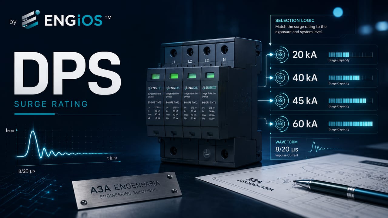
Technical guide to 20, 40, 45 and 60 kA SPDs: differences among In, Imax and Iimp, classes, Up, Up/f, Uw, ISCCR and an engineering sizing method.
Check it out!
The values 20 kA, 40 kA, 45 kA and 60 kA are prominently displayed in SPD catalogs, but they cannot be interpreted as a simple scale from “weak protection” to “strong protection”. A value in kiloamperes only makes sense when you know which quantity it represents, which waveform is associated with the test and which device class is being analyzed.
In a Class II SPD, the value may refer to the nominal discharge current In or the maximum discharge current Imax, both normally associated with an 8/20 µs waveform. In a Class I SPD, the relevant quantity is Iimp, which involves not only the peak value but also charge transfer and specific energy. In a Class III SPD, the test parameter is Uoc, associated with the combination-wave generator.
Therefore, comparing a “20 kA” SPD with a “40 kA” SPD without reading the datasheet may mean comparing different quantities. And even when both specify In or Imax, the device with the higher current rating does not necessarily provide lower residual voltage, better coordination or greater suitability for the installation.
Sizing must answer two independent questions: how much surge current must the SPD withstand at the point where it will be installed? and what effective voltage must remain at the terminals of the protected equipment? The first leads to Iimp, In and Imax; the second leads to Up, Up/f and Uw.
It is not enough to choose a higher-kA SPD and install it in the panel. The design must verify the condition of the electrical installation, the TN, TT or IT system, available short-circuit current, backup protection, grounding, equipotential bonding, integration with LPS/SPM, connection length and coordination with other stages. In existing installations, these conditions may require electrical diagnosis and upgrades before simply replacing the device.
What does kA mean in an SPD?
Kiloampere is a unit of current, but an SPD may declare different currents in kA. Correct interpretation requires identifying the symbol next to the value.
| Marking | Meaning | Test / context | Can it be compared directly? |
In | nominal discharge current | Class II, 8/20 µs waveform | only with another In under the same reference |
Imax | maximum discharge current | Class II, 8/20 µs waveform | only with another Imax under the same condition |
Iimp | impulse current | Class I, associated with peak, charge and specific energy | should not be directly equated with In or Imax |
ITotal | total discharge current | multipole SPD | depends on multipole architecture and simultaneous protection modes |
ISCCR | rated short-circuit current of the assembly | safety in the event of SPD failure | it is not surge current |
The first mistake to avoid, therefore, is using only the kA number. One product may highlight “40 kA” as Imax, while another highlights “20 kA” as In. Depending on the product family, the two may have very similar performance or different functions.
For an overview of the device, see SPD: what it is, what it is used for, classes, sizing and installation.
In, Imax and Iimp: how to interpret the declared currents
ABNT NBR IEC 61643-11 defines In as the peak value of a current passing through the SPD with an 8/20 µs waveform. It is the central quantity in Class II tests.
The word “nominal” should not be confused with the circuit’s rated load current. In is not the current that supplies the installation. It is a transient surge current used to characterize the SPD.
Why the 8/20 µs waveform matters
The waveform defines how the current rises and decays over time. A 20 kA 8/20 µs current has very different energy content and stress from a 20 kA current associated with a longer impulse.
Thus, the peak value alone does not describe the stress on the SPD.
What In tells the designer
In helps assess the device’s capability against repetitive surges and is part of determining Class II performance. Selection must be related to the expected stress at the point of installation.
The value alone does not define:
Uc;Up;Imax;ISCCR;- backup protection;
- coordination with another SPD;
- actual service life;
- suitability for a TN, TT or IT system.
Imax: maximum discharge current
ABNT NBR IEC 61643-11 defines Imax as the peak value of an 8/20 µs current passing through the SPD, with an amplitude specified by the manufacturer. The standard establishes that Imax is greater than or equal to In.
This point explains a large part of the confusion in the market.
An SPD may be marketed as “40 kA”, while its datasheet states, for example:
In = 20 kA;Imax = 40 kA.
Another may be advertised as “20 kA” because the marketing material highlights In.
Without reading the datasheet, the comparison is incomplete.
Iimp: why Class I should not be compared directly with 20 or 40 kA Class II
Iimp is the impulse current used for Class I tests. The definition incorporates:
- peak value;
- charge transfer
Q; - specific energy
W/R; - event duration.
ABNT NBR 5419-4:2026 shows preferred Iimp values associated with different charge and specific-energy values. Increasing Iimp, for example, greatly increases the specific energy involved.
This means that a Class I SPD with Iimp = 12.5 kA is not “weaker” than a Class II SPD with Imax = 40 kA simply because 12.5 is numerically lower than 40. They are different test regimes.
The distinction between classes is discussed in more detail in Class 1, Class 2 and Class 3 SPDs.
20 kA, 40 kA, 45 kA and 60 kA: why do these values appear so often?
Manufacturers organize product families around standardized or commercially convenient ratings. Class II products commonly specify In or Imax in ranges such as 10, 20, 40, 45, 60 kA or higher.
These values do not, by themselves, constitute a mandatory standards-based sequence for every installation.
The correct question is: what current is expected at the point, and which product parameter represents that capability?
20 kA SPD
It may be suitable in certain internal distribution boards, final circuits or applications where the expected 8/20 stress is compatible. It may also appear as the In of a device whose Imax is higher.
It should not automatically be considered “residential” or “weak”.
40 kA SPD
This is a very common rating in Class II products. It may represent In or Imax depending on the product family.
In distribution boards, 40 kA may provide capacity margin and service life, but it does not replace verification of Up, Uc, ISCCR and coordination.
45 kA SPD
The 45 kA value appears in several commercial product lines. Technically, it must be treated exactly like the others: identify whether it is In or Imax, the class, waveform, Up and test conditions.
There is no general standards-based rule making 45 kA superior to 40 kA for every installation.
60 kA SPD
A higher current rating may increase energy capability or margin against events, but that gain only matters if the installation can actually impose that stress and the other parameters are suitable.
Oversizing current without improving Up/f, connection layout, grounding or signal protection may provide little technical benefit.
Does a higher-kA SPD provide better protection?
Not necessarily.
Final protection depends on two dimensions:
1. energy capability, related to current and test regime; 2. voltage limitation, related to Up and the effective Up/f in the installation.
Consider two Class II SPDs:
- SPD A:
In = 20 kA,Imax = 40 kA,Up = 1.2 kV; - SPD B:
In = 40 kA,Imax = 60 kA,Up = 1.8 kV.
If the expected stress is below 20 kA and the load has low impulse withstand capability, SPD A may provide better voltage protection, provided the other criteria are met.
The example is not intended for product selection without a design; it shows why “more kA” does not automatically mean “better”.
Up: the parameter that must not disappear from the comparison
Up is the voltage protection level declared by the manufacturer.
During operation, the SPD does not reduce the voltage to zero. It limits the overvoltage to a residual level. The protected equipment must withstand this value with an adequate margin.
NBR 5419-4:2026 extends this concept to Up/f, the effective protection level at the branch.
For voltage-limiting SPDs, a simplified expression is:
Up/f = Up + ΔU
where ΔU represents the voltage drop associated with connection conductors, terminals and branch components.
A 60 kA SPD installed with long conductors may provide a worse Up/f than a lower-current SPD installed correctly.
Uw: equipment impulse withstand voltage
Uw is the equipment’s impulse withstand voltage. The objective is to keep Up/f below Uw, observing the applicable margins.
NBR 5419-4:2026 presents specific conditions:
Up/f ≤ Uwwhen the distance between the SPD and equipment is negligible;Up/f ≤ 0.8 Uwfor circuits no longer than 10 m;Up/f ≤ 0.5 Uwfor up to 10 m when failure of the internal system is critical;- for distances greater than 10 m, additional SPDs, two-port SPDs, shielding or improved routing may be required.
Therefore, choosing between 20, 40 or 60 kA does not answer the question of the effective voltage that will reach the load.
How NBR 5410 addresses In and Iimp
The consulted edition of ABNT NBR 5410:2004, corrected version 2008, establishes minimum current criteria according to the purpose of the SPD.
For protection against atmospheric overvoltages transmitted by the external line and switching surges, the standard establishes a minimum In per protection mode and provides specific conditions for the SPD between neutral and PE in certain systems.
When protection is intended for currents associated with direct lightning flashes to or near the building, the standard provides guidance for determining Iimp and specifies minimum values for situations where the current cannot be determined.
These values are minimum normative reference values, not justification for always choosing the smallest product that meets the number.
NBR 5419-4:2026 complements the reasoning with analysis of current distribution according to the Lightning Protection Level and the structure’s architecture.
Lightning current does not reach a single SPD in its entirety
In a direct strike, the current is distributed among several paths:
- grounding subsystem;
- protective conductors;
- PEN or PE;
- power lines;
- signal lines;
- metallic piping;
- interconnections with other structures.
NBR 5419-4:2026 shows that the portion passing through an SPD depends strongly on this division.
In the Annex D example, for LPL I and without a specific calculation, an approximation is presented in which part of the current is dissipated through grounding and part returns through the lines. In another example, the presence of three metallic lines reduces the share of current assigned to the electrical supply.
The design lesson is direct: Iimp must represent the expected share at the point, not the total lightning current.
How to size SPD current: an engineering sequence
1. Define the required class
Before choosing 20, 40 or 60 kA, determine whether the stress should be addressed as Class I, II or III.
- direct current S1/S3: evaluate Class I;
- induced surges S2/S4 and switching: evaluate Class II;
- complementary stage near the load: evaluate Class III.
2. Determine which quantity must be specified
For Class I, the central quantity is Iimp.
For Class II, In is the nominal test quantity and Imax may be used as an additional characteristic.
For Class III, Uoc is part of the characterization.
3. Estimate or calculate the stress at the point
Consider:
- Lightning Protection Level;
- source of damage;
- SPD location;
- number of metallic lines;
- grounding system;
- interconnection between structures;
- current division;
- field experience and design data.
Are you sizing SPDs for an installation with an LPS, multiple distribution boards or critical loads?
The kA rating must be defined from the expected stress at the point, not merely from the commercial range available. The Surge Protection Measures (SPM) Design consolidates current, class, Uc, Up, Up/f, grounding and coordination into a single architecture.
4. Adopt a coherent margin
A capacity above the expected current may increase robustness and, in many cases, SPD service life.
But the margin should not turn the specification into a competition for the highest kA rating.
5. Check Up and Up/f
Do not accept increased energy capability at the expense of poorer voltage limitation without analysis.
6. Check Uc and TOV
An SPD with a high discharge-current rating may fail or degrade if Uc and TOV behavior are incompatible with the network.
7. Check ISCCR and backup protection
Surge current and short-circuit current are different phenomena.
The interface with a circuit breaker or fuse is detailed in SPD and Circuit Breaker: backup protection, sizing and installation.
Does the panel have high short-circuit current or critical selectivity?
In this scenario, the “SPD kA” cannot be analyzed in isolation. ISCCR, backup protection, interrupting capacity and system coordination must be compatible. See the Short-Circuit, Selectivity and Protection Coordination Study.
8. Check coordination with downstream stages
A high-capacity service-entrance SPD does not eliminate the need for coordination with internal SPDs.
In and Imax do not define service life by themselves
The service life of an SPD depends on the accumulated energy of events, number of operations, temperature, temporary overvoltages, product quality, condition of connections and actual stress.
In general terms, greater energy capability may provide more margin for events below the limit. But there is no universal conversion such as “40 kA lasts twice as long as 20 kA”.
Degradation is associated with the overall stress profile and internal technology.
Is a 20 kA SPD sufficient in a residential installation?
There is no universal answer based solely on residential use.
You must verify:
- overhead or underground service entrance;
- region and exposure;
- existence of an LPS;
- panel location;
- grounding system;
- distance to sensitive loads;
- SPD classes used;
Up;Uc;- coordination.
An SPD with In = 20 kA may be suitable in one application and insufficient in another.
Is a 40 kA SPD sufficient in an industrial switchboard?
There is no automatic answer here either.
In an industrial main low-voltage switchboard, in addition to surge current, the available short-circuit current may be high. This requires checking ISCCR, backup protection and the interrupting capacity of the circuit breaker/fuse.
In addition, the presence of an LPS or external lines may require Class I, in which case a “40 kA Class II” device does not replace the evaluation of Iimp.
For existing installations, SPD and SPM Inspection, Diagnosis and Upgrade makes it possible to verify the device under the actual conditions of the panel.
Is there an SPD installed, but no one knows whether 20, 40 or 60 kA is actually suitable?
In existing installations, the diagnosis should verify the declared quantity, class, device condition, Uc, Up, ISCCR, backup protection, grounding and coordination. Learn about SPD and SPM Inspection, Diagnosis and Upgrade.
Is a 45 kA SPD better than 40 kA?
The 5 kA difference may be technically minor if the main parameters are different.
Before drawing a conclusion, compare:
- the symbol associated with the value;
- class;
In;Imax;Iimpwhen applicable;Up;Uc;ISCCR;- TOV;
- coordination;
- status indication;
- backup protection.
If a “45 kA” SPD has worse Up, unsuitable Uc or lower ISCCR, it is not automatically superior to a “40 kA” SPD.
Is a 60 kA SPD oversized?
It may or may not be.
A higher value may be justified when:
- the expected stress is high;
- there is a high frequency of surges;
- criticality requires greater margin;
- the incremental cost is small relative to the required availability;
- the product family maintains suitable
Up,Ucand other parameters.
It may be technically unnecessary when the expected stress is much lower and no other benefit is obtained.
Oversizing should be a conscious decision, not a substitute for calculation.
SPD current and the TN, TT or IT system
The grounding system influences protection modes and voltage distribution.
NBR 5410 establishes different connections between phase, neutral, PE and PEN depending on the system. In some configurations, the N-PE SPD may be subjected to combined currents from multiple phases, which changes the current required in that mode.
Therefore, a multipole assembly must be analyzed by mode and, where applicable, by ITotal.
Multipole SPDs and ITotal
ABNT NBR IEC 61643-11 defines ITotal as the current flowing through the PE or PEN conductors of a multipole SPD during the total discharge-current test.
This parameter is particularly relevant for Class I SPDs used for lightning equipotential bonding, because several protection modes may conduct simultaneously.
In a three-phase system, looking only at the per-pole rating may not represent the total stress on the assembly.
Higher Imax and lower Up: which should be prioritized?
The answer depends on the design.
If energy capability is already sufficient for the expected current, reducing Up may be more important for protecting sensitive loads.
If the SPD is close to its energy limit, increasing capacity may take priority.
Selection should seek a solution that simultaneously meets:
- current capability;
- voltage limitation;
- continuous voltage;
- TOV;
- short-circuit requirements;
- coordination.
There is no need to choose between current and voltage when the correct product can meet both requirements.
How conductor length changes the result
The kA capability remains the same in the catalog, but the effective voltage at the load may increase due to the inductance of the connection conductors.
NBR 5410 recommends short, straight connections and, in applicable arrangements, prefers a total length of approximately 0.5 m or less.
NBR 5419-4:2026 gives, as an example, an order of magnitude of 0.1 kV per kA per meter at the service-entrance connection. Thus, 10 kA over 1 m can add about 1 kV to the effective level.
This shows why replacing a 20 kA SPD with a 60 kA device without correcting a long connection may not solve the vulnerability.
Example 1: two Class II SPDs advertised as 40 kA
Consider two products:
Product A
In = 20 kA;Imax = 40 kA;Up = 1.2 kV;Uc = 275 V.
Product B
In = 40 kA;Imax = 40 kA;Up = 1.8 kV;Uc = 275 V.
Both may be marketed as “40 kA”, but they are not equivalent.
B has higher In; A has lower Up. The decision depends on the expected current, the load and coordination.
Example 2: Class I 12.5 kA versus Class II 40 kA
Numerically comparing 12.5 and 40 is inappropriate.
The first value may represent Iimp, with much greater charge and specific-energy requirements. The second may represent 8/20 µs Imax.
The correct question is which class and energy the point requires.
Example 3: main switchboard with high short-circuit current
A 40 kA Class II SPD may have excellent surge capability, but its SPD + disconnector assembly must withstand the prospective short-circuit current at the busbar.
If ISCCR is lower than the available current, the solution is unsuitable regardless of the Imax value.
This is one reason why Surge Protection Measures Design should interface with short-circuit studies and protection coordination in industrial installations.
What to request in a datasheet
When specifying or comparing SPDs, look for at least:
| Field | Why it matters |
| test class | defines the device’s test regime |
Iimp | Class I and impulse current |
In | Class II and nominal 8/20 current |
Imax | declared maximum 8/20 capability |
Uoc | Class III |
Uc | maximum continuous operating voltage |
Up | voltage limitation |
ISCCR | short-circuit safety |
| TOV | behavior under temporary overvoltage |
| protection modes | where the device operates |
| disconnector | failure behavior |
| status indication | maintenance |
| coordination | compatibility with other stages |
Without these data, “40 kA SPD” is an incomplete specification.
Common mistakes when choosing the kA rating
Choosing the largest number in the catalog
This may increase cost without improving actual protection.
Confusing In and Imax
Two products advertised with the same kA rating may have different nominal discharge currents.
Comparing Iimp and Imax
They are quantities from different test regimes.
Ignoring Up
An SPD capable of conducting high current may limit voltage at a level that is unsuitable for the load.
Ignoring Uc
A 60 kA SPD with incorrect Uc is still unsuitable.
Ignoring short-circuit conditions
ISCCR and backup protection must be compatible with the busbar.
Choosing kA by building type
“20 kA residential” and “40 kA industrial” are oversimplifications without sufficient technical basis.
Failing to coordinate stages
The largest SPD at the service entrance does not guarantee that distant equipment is protected.
Failing to consider power and signal interfaces
The load may receive a surge through another metallic interface.
Relationship between 20/40/60 kA and SPM design
Current-based selection is no longer a simple decision when there are:
- LPS;
- critical systems;
- multiple distribution boards;
- long distances;
- external lines;
- multiple structures;
- telecommunications and automation;
- high short-circuit current;
- continuity requirements;
- a history of failures.
In these situations, the kA rating must be calculated or justified within the SPM architecture.
The SPM Design turns this analysis into diagrams, specifications, design-criteria documentation, coordination and procurement requirements.
How to audit an existing 20, 40 or 60 kA SPD
In an existing installation, the inspection should verify:
- which quantity the value represents;
- class;
- location;
- source of damage;
Uc;Up;ISCCR;- backup protection;
- module condition;
- conductor lengths;
- coordination;
- subsequent changes to the panel;
- transformer changes;
- new connected systems.
Replacing an SPD simply because “the current one is 20 kA and the new one is 40 kA” is not a diagnosis.
The appropriate route is SPD and SPM Inspection, Diagnosis and Upgrade.
Summary: which SPD should you choose among 20, 40, 45 or 60 kA?
There is no universal answer based on the highest number.
The correct sequence is:
1. identify the class; 2. identify whether the value is In, Imax or Iimp; 3. determine the expected stress at the point; 4. check Up and Up/f against Uw; 5. check Uc and TOV; 6. check ISCCR and backup protection; 7. coordinate with other SPDs; 8. document the selection.
If 20 kA already exceeds the expected stress with adequate margin and provides better Up, a 60 kA product may provide no relevant gain. If the expected current exceeds 20 kA, the 20 kA SPD is unsuitable even if it has excellent Up.
The kA number is one piece of the specification. Correct sizing emerges when current, voltage, energy, installation and coordination are analyzed as a single system.
Technical references
[1] ASSOCIAÇÃO BRASILEIRA DE NORMAS TÉCNICAS. ABNT NBR IEC 61643-11:2021, versão corrigida 2022 — Dispositivos de proteção contra surtos de baixa tensão — Parte 11. Available at: ABNT Catalog.
[2] ASSOCIAÇÃO BRASILEIRA DE NORMAS TÉCNICAS. ABNT NBR 5419-4:2026 — Proteção contra descargas atmosféricas — Parte 4. Available at: ABNT Catalog.
[3] ASSOCIAÇÃO BRASILEIRA DE NORMAS TÉCNICAS. ABNT NBR 5410:2004, versão corrigida 2008 — Instalações elétricas de baixa tensão. Available at: ABNT Catalog.
[4] INTERNATIONAL ELECTROTECHNICAL COMMISSION. IEC 61643-11:2011 — Low-voltage surge protective devices — Part 11. Available at: IEC Webstore.
Frequently asked questions
It depends on the datasheet. The value may represent In or Imax in a Class II SPD, for example. The symbol and associated waveform must be identified before interpreting the capability.
Not necessarily. If both meet the expected current, parameters such as Up, Uc, ISCCR, TOV, coordination and installation may be more decisive for final protection.
In is the nominal discharge current used in Class II tests. Imax is the maximum 8/20 discharge current declared by the manufacturer and is greater than or equal to In.
No. Iimp is the impulse current associated with Class I tests and involves peak value, charge transfer and specific energy. Imax is a maximum 8/20 current associated with Class II.
The numerical difference alone does not support that conclusion. You must compare which quantity is being stated, as well as class, Up, Uc, ISCCR, TOV and coordination.
It may be technically acceptable in many applications, but the higher value does not compensate for incorrect Uc, high Up, lack of coordination or short-circuit incompatibility.
There is no single value defined solely by residential use. Service entrance, LPS, exposure, grounding system, class, Up, Uc and coordination must be considered.
There is no universal value here either. Industrial installations may require greater capability, but selection must consider source of damage, expected current, LPS, short-circuit conditions and criticality.
No. In, Imax and Iimp are surge currents. The backup circuit breaker or fuse is selected according to short-circuit current, ISCCR and the manufacturer’s instructions.
Greater capability may provide margin and reduce relative stress per event, but service life also depends on the number and energy of surges, TOV, temperature, technology and installation conditions.
The expected current at the point must be estimated or calculated, the class identified and the other protection parameters verified. The isolated number is not sufficient.
Only after verifying equivalence of class, Uc, Up, protection modes, ISCCR, backup protection and coordination. The same voltage and a higher kA rating do not guarantee equivalence.
Complementary technical materials
Related solutions
Related engineering services
- Surge Protection Measures (SPM) Design
- SPD and SPM Inspection, Diagnosis and Upgrade
- Short-Circuit, Selectivity and Protection Coordination Study
- Low-Voltage Electrical Design
Related technical content
- SPD: what it is, what it is used for, classes, sizing and installation
- SPD Coordination
- SPD and Circuit Breaker
- NBR 5419-4: internal LPS, SPDs and system protection
