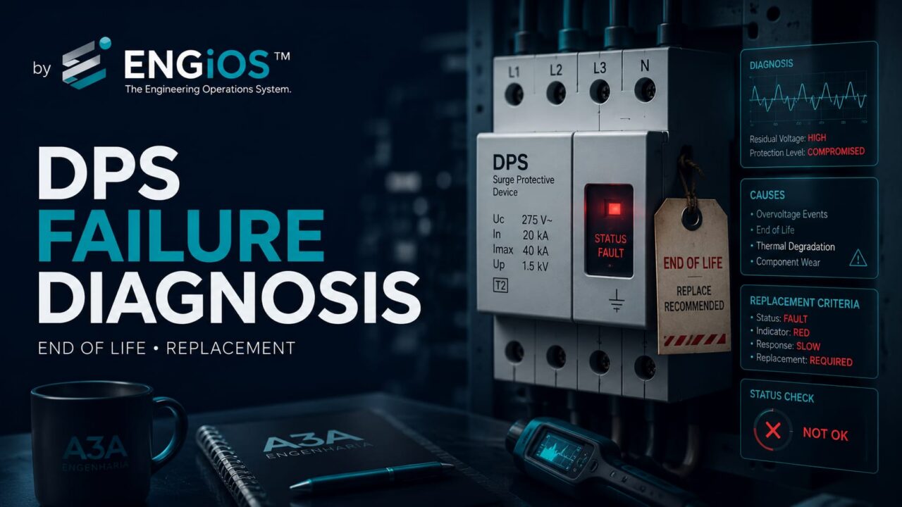
Learn what a red SPD status indication means, the main failure causes, and why replacing the module without diagnosing Uc, TOV, neutral, grounding, backup protection and coordination can make the problem recur.
Check it out!
A failure indication on a surge protective device should not be interpreted solely by the color of a window, LED or display. The SPD has status-signaling mechanisms defined by its manufacturer, but engineering diagnosis begins after that indication: it is necessary to determine whether the protective element reached end of life, whether the internal disconnector operated, whether a temporary overvoltage occurred, whether an impulse stress exceeded the intended level, whether the device was incorrectly specified, or whether another condition exists in the electrical installation.
What does a red indication on an SPD mean? In many models, a red indication means the protective element has been disconnected, has reached an end-of-life condition or no longer provides its intended protective function. However, color and signaling logic are not universal: correct interpretation depends on the manufacturer, model and technical documentation of the device.
From an engineering standpoint, the status indication tells you there is a condition that must be checked, but it does not automatically identify the cause. An SPD can reach end of life because of successive surge currents, an exceptional event, TOV, unsuitable Uc, neutral loss or displacement, incompatible backup protection, or deficiencies in coordination, grounding and equipotential bonding.
Replacing the cartridge may therefore be necessary to restore protection, but it should not end the investigation when failure is recurrent, when there are signs of heating or when there are doubts about the original design. In such cases the installation must be assessed as a system: power supply, TN/TT/IT arrangement, LPS, SPM, switchboards, backup protection, short-circuit current, grounding and documentation.
How to interpret the SPD status indication
ABNT NBR IEC 61643-11 defines a status indicator as a device that indicates the operating status of an SPD or part of it. The indicator may be local, visual or audible, and may also provide remote signaling through an output contact.
ABNT NBR 5410 requires that when an SPD ceases to perform its protective function because of failure or deficiency, that condition be evidenced by a status indicator or suitable protective device.
This does not mean that every red color has exactly the same meaning across all manufacturers. The equipment manual must be consulted. In a modular SPD with a replaceable cartridge, the indication may mean the protective module has been internally disconnected. Other products may use different signals for pre-alarm, failure or maintenance requirements.
The operational rule should be simple: if the manufacturer defines the visual status as loss of the protective function, the circuit should not be considered adequately protected merely because it remains energized.
Why an SPD can fail or reach end of life
An SPD is designed to limit overvoltages and divert surge currents. Each stress event can subject its components to thermal and electrical stress. Over time, this stress may cause degradation.
ABNT NBR IEC 61643-11 explicitly addresses performance degradation and requires operating-duty, thermal-stability, failure-behavior and temporary-overvoltage tests. This shows that SPD life depends not only on “how many lightning strikes occurred,” but also on how the device is stressed by the network.
The main causes that deserve investigation include:
- successive surge currents over the service life;
- an impulse event above the expected capability;
- Uc unsuitable for the voltage applied to the protection mode;
- temporary overvoltage — TOV — caused by an abnormal network condition;
- neutral loss or displacement;
- inadequate coordination between SPDs at different stages;
- incorrect selection of Class I, II or III for the installation point;
- incompatible backup protection;
- prospective short-circuit current above the capability of the assembly;
- poor connections or terminal heating;
- thermal environment outside intended conditions;
- installation inconsistent with grounding and equipotential bonding;
- changes to the installation made after the original design.
In an isolated occurrence after a severe event, the cause may be relatively clear. In recurrent failures, simple replacement should give way to a structured investigation.
Recurring failure should not be treated merely as component replacement. If the same SPD fails again, the installation needs to be assessed for TOV, Uc, neutral condition, grounding, surge energy, backup protection and coordination.
Incorrect Uc can cause premature failure
Maximum continuous operating voltage Uc is the highest RMS voltage that may be continuously applied to the SPD protection mode. It must be selected according to the actual voltage between the terminals to which the device is connected and the earthing arrangement.
NBR 5410 provides minimum Uc values as a function of Uo, U and TT, TN and IT arrangements. This means choosing an SPD “rated 175 V because the network is 127 V” or “275 V because the network is 220 V” may be an inadequate simplification if one does not know exactly which conductors the device is connected between and what temporary overvoltages can arise.
A Uc that is too low for actual conditions can subject the SPD to continuous or frequent stress. A Uc that is excessively high can impair the intended protection-level tradeoff. The article 175 V or 275 V SPD: Uc, network voltage and TOV examines this subject in depth.
When SPDs fail repeatedly, checking installed Uc and the voltage actually applied in each protection mode must be part of the diagnosis.
Temporary overvoltage is not the same as a lightning surge
One of the most common mistakes is to attribute every SPD failure to lightning. The SPD can also be exposed to temporary overvoltages, known as TOV. They last far longer than a lightning impulse and may result from network faults, neutral problems, abnormal grounding conditions or other electrical events.
ABNT NBR IEC 61643-11 establishes specific TOV tests because the behavior of the device under a sustained abnormal voltage differs from its behavior under a transient surge.
If the real cause is TOV, simply installing an SPD with a higher kA value may not solve the problem. In, Imax and Iimp describe capabilities related to surge currents; they do not replace correct selection of Uc and temporary-overvoltage withstand.
Neutral loss can damage SPDs and other equipment
In systems with a distributed neutral, a fault or interruption in the neutral can significantly alter voltages applied to loads and protection modes. Depending on network topology, unbalanced loads may be exposed to voltages well above their ratings.
In that situation, the SPD may be only one of the affected devices. If there is a history of burned lamps, damaged power supplies, electronic failures or abnormal voltages together with end-of-life SPDs, the investigation must go beyond the SPD itself.
The diagnosis should verify neutral connections at the source and switchboards, busbars, splices, terminal tightness, continuity, TN-C-S transitions, generators, UPS systems, transfer switches and any point where the neutral may have been altered or improperly switched.
A higher-kA SPD does not automatically correct recurrent failure
When a 20 kA SPD fails, an intuitive response is to replace it with a 40 kA or 60 kA unit. This decision only makes sense if the analysis shows that the device’s surge-current capability was actually insufficient for the existing stress.
ABNT NBR IEC 61643-11 distinguishes In, Imax and Iimp, while NBR 5419-4 relates current selection to the expected share at the installation point and to sources S1, S2, S3 and S4.
An SPD with greater energy capability may increase robustness and service life, but it can still fail if Uc is wrong, if TOV occurs, if backup protection is inadequate or if the device is installed at the wrong stage of the cascade.
See 20 kA, 40 kA, 45 kA or 60 kA SPD: how to size it.
The SPD class must match the exposure
The presence of an LPS or impulse-current sources associated with direct lightning changes the test class required at the service entrance. NBR 5419-4:2026 indicates Class I SPDs where direct lightning currents must be considered and Class II for induced effects or switching overvoltages in other scenarios.
Installing only Class II where the architecture requires Class I may expose the device to energy above that for which the stage was designed. Likewise, using Class I does not eliminate the need for downstream stages to reduce effective voltage near equipment.
The article Class 1, Class 2 and Class 3 SPDs details this distinction.
Recurring failure may indicate missing cascade coordination
A coordinated SPD system distributes stress throughout the installation. The idea is not to install many devices, but to make each stage perform a function compatible with its position and adjacent stages.
NBR 5410 requires coordination when SPDs exist at more than one point. NBR 5419-4 reinforces energy coordination and recommends that the manufacturer provide sufficient information to achieve it.
If a secondary-switchboard SPD fails repeatedly, the following questions should be asked:
- is there an adequate SPD at the origin?
- is the upstream stage Class I or II according to exposure?
- were the devices coordinated by the manufacturer?
- is there compatible distance or a decoupling element?
- is the secondary switchboard receiving a larger current share than expected?
- does any metallic line bypass the protection stage?
The article SPD coordination: cascading, energy and Up/f develops this diagnosis in more depth.
SPD condition must be assessed together with backup protection
An internal SPD failure can develop into a short circuit. NBR 5410 therefore addresses overcurrent protection associated with SPDs and alternatives for positioning the backup device.
ABNT NBR IEC 61643-11 uses ISCCR to express the maximum prospective short-circuit current of the network for which the SPD characteristics, together with the specified disconnector, are intended.
If the SPD failed with thermal damage, an open fuse, a tripped circuit breaker or marks in the switchboard, the investigation should verify:
- prospective short-circuit current at the point;
- installed backup device;
- rated current and trip curve where applicable;
- maximum limit recommended by the manufacturer;
- interrupting capacity of the devices;
- conductor cross section and condition;
- terminal tightness and integrity;
- signs of arcing or heating.
The article SPD and Circuit Breaker: backup protection, sizing and installation complements this analysis.
Long conductors can worsen protection without causing SPD failure
Not every SPD deficiency appears as a red cartridge. A device can remain operational and still deliver insufficient effective protection because of its installation.
NBR 5419-4 defines Up/f as the effective protection voltage on the branch, including the effect of ΔU in conductors. NBR 5410 recommends short and straight connections, preferably with a total length around 0.5 m in the reference configuration.
This means an SPD inspection should evaluate both the physical status of the device and the connection layout. Long conductors, loops, unsuitable routing and excessive distance from the PE busbar can increase the voltage that reaches protected equipment during a surge.
Poor grounding can be behind poor surge protection
The SPD operates within an equipotential-bonding network. If PE, PEN, main bonding points, busbars and the grounding system are not correctly established, surge current may find unintended paths or produce significant potential differences within the installation.
It is not correct to diagnose an SPD merely by measuring “how many ohms the grounding system has.” Engineering must assess topology, continuity, equipotential bonding, connections, LPS integration and current paths.
The article Electrical Earthing Arrangements: TN, TT and IT and the Grounding and Equipotential Bonding solution develop this interface in greater depth.
SPD failure after a lightning event
When there is evidence of direct lightning to the structure or nearby, the investigation should consider the complete lightning-protection system.
It is necessary to verify the external LPS, equipotential bonding connections, SPD at the origin, other cascade stages, signal lines and possible equipment damage. NBR 5419-4 considers different sources of damage and shows that current can be distributed through multiple metallic lines connected to the structure.
Replacing only the visibly damaged SPD can leave other stages degraded or fail to identify latent damage.
SPD failure without an apparent storm
The absence of a recent storm is an important clue. In this case, hypotheses such as TOV, neutral loss, switching overvoltage, power quality, incorrect connection, unsuitable Uc or connection heating become more relevant.
In recurrent events, it may be useful to combine physical inspection with measurement and monitoring of electrical quantities. The Power Quality Analysis and Diagnosis service is a possible route when symptoms indicate abnormal power-supply behavior.
Not every SPD failure is caused by lightning. When there is no associated atmospheric event, temporary overvoltage, neutral loss and power quality must be included in the diagnosis.
When cartridge replacement is enough — and when investigation is required
Simple replacement may be reasonable when there is a known cause, an isolated event, a correctly specified device and the remainder of the installation has already been validated. Even then, manufacturer documentation and the condition of the assembly should be checked.
A technical investigation is especially recommended when:
- the same SPD fails again in a short time;
- several SPDs fail in different switchboards;
- there are signs of heating or carbonization;
- the backup circuit breaker or fuse trips repeatedly;
- equipment also shows failures or damage;
- there are reports of voltage variation;
- there were recent changes to the transformer, generator, UPS or photovoltaic system;
- the earthing arrangement is undocumented;
- the LPS was modified or lacks updated documentation;
- installed SPDs have different classes, Uc or capabilities without documented criteria;
- there is no calculation record or SPM design.
In these cases, SPD failure is a symptom to be interpreted rather than simply a corrective-maintenance item.
How to diagnose an installation where SPDs keep failing
A structured analysis can be divided into four workstreams.
1. Documentation
Review the single-line diagram, electrical design, LPS design, risk analysis, grounding documentation, switchboard list, SPM design report, specifications and maintenance records.
2. Field survey
Confirm supply origin, transformers, main LV switchboard, secondary boards, N/PE/PEN, main bonding points, installed SPDs, backup protection, connection lengths, indication, cartridge condition and critical loads.
3. Electrical verification
Check voltages, balance, neutral condition, short-circuit current when required, protection coordination and possible power-quality events.
4. SPM analysis
Verify classes, Uc, Up, In/Imax/Iimp, ISCCR, coordination among stages, distance to equipment, Up/f, interfaces with signal lines and compatibility with the LPS.
This process may lead to simple component replacement, correction of installation details or the need for a broader redesign.
Detailed engineering report and SPD diagnosis
When an installation has a history of failures, missing documentation or multiple nonconformities, a detailed engineering report can be useful to convert field observations into technical evidence, issue classification and prioritized recommendations.
The Detailed Electrical Installation Report may cover the overall condition of the installation, while Inspection, Diagnosis and Retrofit of SPDs and SPM focuses specifically on surge protection.
The choice among inspection, due diligence, engineering report or design depends on the problem to be solved and the level of existing documentation.
When the solution is a retrofit design
If the diagnosis shows existing SPDs were installed without coordination, with unsuitable classes, incompatible Uc, no protection at the origin or poor integration with LPS and grounding, the solution is no longer spot maintenance.
Replacing the cartridge does not correct an inadequate protection architecture. When the problem involves class, Uc, coordination, location or integration with the LPS and grounding, the solution is to redesign the SPM with documented criteria.
In this scenario, the correct approach is to develop a retrofit architecture. The Surge Protection Measures — SPM Design can define location, classes, protection modes, SPD parameters, coordination, backup protection, installation details and interfaces with equipment.
Depending on the causes identified, the scope may also require a Low-Voltage Electrical Design, LPS Design or Grounding Design.
Responsible engineer and traceability of the retrofit
In professional installations, recurrent replacement of devices without diagnosis can hide a broader engineering deficiency. When an intervention changes switchboards, protection, grounding, LPS or installation documentation, technical responsibility and traceability of decisions are important.
The design should record criteria and specifications. Execution should follow approved documents. Final verification should confirm assembly, torque, connections, status indication and consistency with the coordinated system.
This cycle — diagnosis, design, execution and verification — is more robust than a reactive approach of replacing the cartridge whenever the indicator turns red.
A red indicator reports status; it does not identify the cause by itself
ABNT NBR IEC 61643-11 defines the status indicator as the device that reports the operating condition of the SPD or part of it. The standard permits local, visual and audible indication as well as remote signaling through an output contact. This is different from saying that indicator color diagnoses the mechanism that caused the failure.
A cartridge indicating failure may have been disconnected by thermal degradation, operation of an internal disconnector, stress above device capability, prolonged temporary overvoltage or another mechanism anticipated by the manufacturer. The technical procedure should therefore separate two questions: is the SPD still operational? and what condition caused the device to reach this state?
The first answer comes from product indication and documentation. The second requires analysis of the electrical system, event history, voltage, neutral, grounding, coordination, backup protection and, where applicable, LPS and SPM.
Disconnector, ISCCR and Ifi help explain failures that look like a “burned SPD”
ABNT NBR IEC 61643-11 defines the SPD disconnector as the device that disconnects it from the network to prevent a permanent fault. This disconnector can be internal, external or a combination, and can perform thermal, overcurrent or leakage-current-related functions.
Another critical parameter is ISCCR, the maximum prospective short-circuit current of the network for which the SPD, associated with the specified disconnector, is rated. In voltage-switching SPDs there is also the power-frequency follow current after the impulse and its rated interrupting capability, Ifi. These parameters show why an SPD cannot be assessed solely by In, Imax or Iimp.
If switchboard short-circuit current exceeds the condition for which the SPD + disconnector assembly was specified, failure can have consequences very different from those anticipated in the catalog. Investigation of a failed SPD must therefore compare the installed product with the actual prospective short-circuit current at the point and the backup protection that is really installed.
Degradation, TOV and surge energy are different mechanisms
The product standard defines degradation as an undesirable permanent deviation in performance from the intended condition. It also defines temporary overvoltage, TOV, as a voltage stress applied for a specified interval to verify SPD behavior. These concepts help distinguish phenomena that, in the field, are often grouped together under the statement “the SPD burned out.”
| Possible mechanism | Evidence that should be investigated |
|---|---|
| Aging/degradation | Time in service, number of events, thermal environment, replacement history and condition of other SPDs at the same stage. |
| TOV | Permanent voltage, neutral loss/displacement, installation faults, poor regulation and Uc compatibility. |
| Surge above expected level | Atmospheric event, SPD class, Iimp/In/Imax, position in the system and expected current share at the point. |
| Failure associated with short circuit | ISCCR, backup protection, prospective switchboard current and operation of the associated fuse/circuit breaker. |
| Inadequate coordination | Missing cascade, incompatible SPDs, distance between stages and SPD inside connected equipment. |
A reliable diagnosis does not need to assume immediately which mechanism occurred. It needs to collect enough evidence to eliminate hypotheses and identify the most likely cause or, where that is not possible, record the remaining uncertainties technically.
A higher-kA SPD can increase service life without correcting the cause
Annex D of ABNT NBR 5419-4:2026 introduces an important nuance: increasing the SPD’s energy capability can increase its service life when the device is correctly applied, but this does not mean the higher current value is always the most important criterion. The standard emphasizes that voltage-limiting performance and the relationship among Up, Up/f and Uw remain fundamental.
It also notes that an SPD with lower Up may offer greater protection margin to equipment but may be more susceptible to temporary overvoltages if installed in a poorly regulated system. This reinforces the need to balance energy withstand, protection level and TOV behavior.
Replacing a 20 kA SPD with a 40 kA or 60 kA unit can therefore temporarily mask the problem if the true cause is unsuitable Uc, neutral loss, elevated permanent voltage, inadequate backup protection or coordination error. The article on 20 kA, 40 kA, 45 kA or 60 kA SPDs develops this distinction.
SPD failure also requires a service-continuity decision
NBR 5410 presents different ways to position overcurrent protection associated with an SPD. In one arrangement, SPD failure can be cleared without interrupting circuit supply, preserving service continuity but temporarily leaving the system without that surge-protection stage. In another, operation of the protective device can interrupt the protected circuit itself.
The standard also presents a redundant solution with two SPDs and independent protections to increase the probability of maintaining both supply and protection. This is especially relevant in critical installations, where maintenance must answer not only “which cartridge should be replaced?” but what operating condition remains safe until the failure is corrected?
The diagnosis should preserve evidence before replacement
When there is recurrence, significant damage or operational impact, immediate replacement without documentation can eliminate useful evidence. Before discarding the device, the engineering team should, when safety conditions allow, record the condition found and the data needed to reconstruct the event.
- manufacturer, model, batch and SPD position in the switchboard;
- declared Uc, Up, In, Imax, Iimp, test class and ISCCR;
- specified backup protection and the protection actually installed;
- condition of the indicator, disconnector and any remote contacts;
- condition of N, PE and PEN busbars and equipotential bonding;
- measured voltages and history of neutral loss or power-quality anomalies;
- records of storms, switching, network faults or recent interventions;
- condition of upstream and downstream SPDs and connected equipment.
This record turns a maintenance replacement into technical evidence for root-cause analysis. When needed, it can be consolidated into a Detailed Electrical Installation Report with findings, hypotheses, criticality and a retrofit plan.
After direct lightning, the investigation must extend beyond the switchboard
When there is evidence of lightning to the structure or connected lines, ABNT NBR 5419-4:2026 requires a system-level view. Sources S1 and S3 can introduce relevant impulse currents into the installation, and the portion conducted by SPDs depends on current distribution among grounding, power lines, signal lines, piping and other metallic services.
In this situation, assessing only the failed SPD can leave precisely the elements that conditioned the failure uninspected: external LPS, equipotential bonding, grounding, metallic service entrances, signal-line SPDs, upstream switchboards and cascade protection. The review should interface with the LPS Design and SPM Design.
Critical installations can monitor SPD status remotely
ABNT NBR IEC 61643-11 provides for output contacts associated with the status indicator or disconnector. When a product offers this feature, the design can integrate SPD status with a BMS, supervisory system, building automation, maintenance platform or operational alarm system.
This strategy does not replace inspections, but it reduces the time a critical installation may remain unaware that it has lost a protection stage. In data centers, continuous processes, telecommunications and security systems, remote signaling can form part of the SPM continuity and maintenance philosophy.
The engineering deliverable is the diagnosis and retrofit plan
A recurrent red or failed SPD may require different levels of response: spot inspection, power-quality analysis, as-built survey, detailed engineering report, review of the electrical design, grounding retrofit, LPS inspection or redesign of the SPM system. The appropriate service depends on the evidence and criticality of the installation.
The technical deliverable should transform symptoms into decisions: condition found, documentation reviewed, nonconformities, measurements, probable cause, risks, intervention priority, devices to replace, architecture to correct and acceptance criteria. This is what distinguishes simple component replacement from an engineering diagnosis with traceability.
Red or failed SPD: replace the component, but investigate the cause when necessary
An SPD that has lost its function needs to be handled according to manufacturer instructions and should not remain in place as if it still provided protection. But device failure may contain valuable information about the installation.
If the event was isolated and the architecture is known, replacement may be sufficient. If failures recur, associated damage exists or there is no reliable design, the correct approach is to investigate Uc, TOV, neutral condition, earthing arrangement, LPS, class, current capability, short-circuit current, backup protection and coordination.
Replacing the SPD restores a component. Diagnosing and designing the protection corrects the system.
Technical references
[1] ASSOCIAÇÃO BRASILEIRA DE NORMAS TÉCNICAS. ABNT NBR 5410:2004 — Low-voltage electrical installations.
Frequently asked questions
It depends on the manufacturer and model. In many modular SPDs, red indicates the protective element was disconnected or reached end of life. Product documentation should be consulted to interpret the indicator correctly.
If the manufacturer defines the red indication as failure or loss of function, the circuit should not be considered adequately protected by that module even if it remains energized.
Possible causes include unsuitable Uc, TOV, neutral loss, surge stress above the expected level, wrong class, missing coordination, inadequate backup protection, incompatible short-circuit current, grounding problems or changes to the installation.
Increasing the kA value alone does not guarantee a solution. In, Imax, Iimp, Uc, Up, TOV, ISCCR, class, backup protection and coordination with other stages must be verified.
Yes. In certain systems, neutral loss or displacement can increase voltages applied to loads and protection modes, exposing SPDs and equipment to temporary overvoltages.
Especially when failure is recurrent, occurs in several switchboards, there is thermal damage, other equipment fails, voltage variation exists, the installation was modified or there is no reliable SPD/SPM design documentation.
Complementary technical materials
Related solutions
Related engineering services
- Inspection, Diagnosis and Retrofit of SPDs and SPM
- Surge Protection Measures (SPM) Design
- Detailed Electrical Installation Report
- Power Quality Analysis and Diagnosis
- Low-Voltage Electrical Design
Related technical content
- 175 V or 275 V SPD: Uc, Network Voltage and TOV
- 20 kA, 40 kA, 45 kA or 60 kA SPD
- Class 1, Class 2 and Class 3 SPDs
- SPD Coordination
- SPD and Circuit Breaker: Backup Protection
- Electrical Earthing Arrangements: TN, TT and IT
