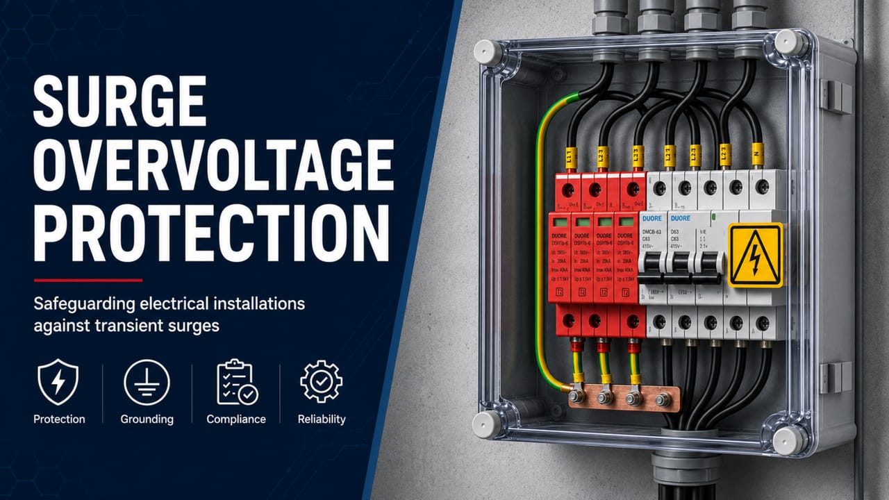
Technical guide to cascaded SPD coordination: Up/f, ΔU, Uw, induced voltage, energy between stages, distances, LPZs, grounding, and design verification.
Check it out!
SPD coordination is the process of making two or more surge protective devices installed at different points in an installation operate as a system. It is not enough to place a high-capacity SPD at the service entrance and a lower-capacity device near the load. Each stage must conduct its appropriate share of current, limit voltage to a level compatible with equipment withstand capability, and pass to the next stage a stress level that it can withstand.
Coordination simultaneously involves energy, voltage, location, distance, conductor impedance, SPD technology, grounding, routing, and equipment characteristics. In a real installation, performance is not determined only by the catalog Up value. The effective voltage reaching the load includes inductive voltage drops in conductors and may receive additional components from electromagnetic induction and propagation phenomena along the circuits.
ABNT NBR 5419-4:2026 treats SPD coordination as one of the basic surge-protection measures and dedicates its normative Annex C to the selection and installation of a coordinated system. ABNT NBR 5410 also requires cascaded SPDs to be coordinated and manufacturers to provide clear information for achieving that coordination. Therefore, “coordination” should not be reduced to the simple sequence Class I → Class II → Class III.
The engineering objective is to ensure that, for the expected surge events, the effective voltage at equipment terminals remains below its impulse withstand voltage and that no SPD is subjected to energy beyond its capability. This requires understanding the complete surge path from the installation boundary to the equipment to be protected.
Installing SPDs in several panels is not sufficient to achieve coordination. Before implementation, the design needs to verify the condition of the electrical installation, the TN, TT, or IT arrangement, available short-circuit current, PE continuity, grounding, equipotential bonding, interfaces with the lightning protection system, signal lines, and existing documentation. When these conditions are unknown or inadequate, the correct step is to diagnose and upgrade the infrastructure before finalizing the LEMP protection measures (MPS) architecture.
What Cascaded SPD Coordination Means
A coordinated SPD system distributes protection in stages. The first stage receives the largest share of energy or impulse current compatible with its position. Subsequent stages refine voltage limitation and protect more sensitive loads or loads located at distances where the previous stage is no longer sufficient.
In a typical architecture, SPDs may be installed at the incoming line or main switchboard, in intermediate panels, near automation panels, adjacent to UPS units, inverters, servers, or sensitive equipment, on signal lines reaching the same equipment, and within the equipment itself.
Coordination must ensure that these devices do not operate incompatibly, do not transfer excessive energy to the next stage, and do not create a false sense of protection based merely on the physical presence of several modules.
For an overview of selection, parameters, and installation, see SPD: What It Is, What It Does, Classes, Sizing, and Installation.
Coordination Is Not Just Selecting Class I, II, and III in Sequence
Test classes describe stress regimes. Class I is associated with the capability to conduct impulse currents related to direct lightning currents; Class II uses the nominal discharge current with an 8/20 waveform; Class III uses the combination-wave generator for supplementary protection. This classification is important, but by itself it does not demonstrate that two products are coordinated.
Two SPDs of different classes may be unsuitable together if the upstream stage lets through energy beyond the downstream stage’s withstand capability, if the effective Up of the first stage is insufficient to protect the second stage or the load, if distances and impedances do not provide the expected decoupling, if internal technologies are incompatible, or if an SPD built into the equipment operates before the external stage and receives excessive energy.
The meaning and role of the classes are discussed in greater depth in Class 1, Class 2, and Class 3 SPDs. In this article, class is treated only as one input to the coordination problem.
The First Criterion Is Understanding the Source of Damage
ABNT NBR 5419-4 organizes sources of stress into events associated with direct lightning flashes to the structure, flashes near the structure, direct flashes to lines, and flashes near lines. Each mechanism produces different current waveforms and distributions.
When direct lightning currents are involved, the entrance stage may need Class I testing and sizing based on Iimp. When protection is intended mainly for induced or switching surges, Class II or III may be appropriate.
Coordination starts before product selection: it is necessary to determine what type of surge reaches each installation boundary and what share of current actually flows along that path.
In installations with a lightning protection system, multiple metallic lines, or interconnected structures, current distribution may be complex. ABNT NBR 5419-4 emphasizes that current does not divide solely according to the number of conductors; impedances, grounding systems, lengths, power and signal lines, piping, and other interconnections influence the share that reaches the SPD.
Voltage Coordination: Up, Up/f, ΔU, Uw, Distance, and Induction
Up is the voltage protection level declared by the manufacturer for the SPD under specified test conditions. It is essential, but it represents device performance at its terminals.
The equipment is connected to the SPD through conductors, terminals, protective devices, and circuit sections that have inductance. During a current impulse with a high rate of change, this inductance produces an additional voltage drop.
For this reason, ABNT NBR 5419-4 uses the concept of the effective protection level in the branch circuit, Up/f.
Up/f: The Central Quantity in Voltage Coordination
For voltage-limiting SPDs, ABNT NBR 5419-4:2026 establishes the simplified relationship:
Up/f = Up + ΔU
For voltage-switching SPDs, treatment may differ, using the higher value between Up and ΔU, with additional considerations related to arc voltage. Combined devices may require more complex relationships.
Voltage coordination should work with Up/f, not only the catalog Up value. This explains why an SPD with Up = 1.5 kV may provide much poorer effective protection if connected by long, poorly routed conductors.
ΔU: How Much Conductors Can Add to Voltage
ABNT NBR 5419-4 provides an order-of-magnitude estimate for an SPD at the entrance of a line: approximately 0.1 kV per kA per meter of connection length.
For example, 1 m of conductor carrying a 10 kA impulse may add approximately 1 kV. If the SPD has Up = 1.5 kV, the installation may present Up/f close to 2.5 kV even before other induced voltages are considered.
This relationship makes clear why the standards recommend connections as short as possible. For the arrangements it addresses, ABNT NBR 5410 indicates a preference for a total connection length not exceeding approximately 0.5 m.
Uw: Coordination Only Makes Sense Relative to the Protected Equipment
Uw is the equipment’s impulse withstand voltage. The protection system must ensure that the effective voltage applied to its terminals remains below this limit with the margin required for the situation.
ABNT NBR 5419-4 establishes progressively more stringent conditions. Depending on the scenario, Up/f may be compared directly with Uw or may need to remain below fractions of Uw. For longer circuits and systems where failure is critical, the required margin becomes more stringent.
Therefore, there is no “optimal coordination” without knowing which equipment is at the end of the chain and what its withstand capability is.
The 10 m Rule and the Need for an Additional Stage
The distance between the SPD and the load influences propagation, reflection, and induction. ABNT NBR 5419-4 recognizes that long circuits may exhibit oscillation phenomena and, under open-circuit conditions at the equipment terminals, overvoltage may reach approximately twice Up/f.
For this reason, the 10 m distance appears as an important reference in protection architectures. When the load is far away, the designer may adopt a new SPD near the equipment, a two-port SPD where technically appropriate, shielded cabling, live conductors and PE routed together, reduced loop area, or a combination of these measures.
This criterion also appears in photovoltaic applications. See Surge Protection in Photovoltaic Systems.
Ui: Induced Voltage That Does Not Appear in the SPD Catalog
Coordination may fail even when Up/f appears adequate if the circuit forms a large loop exposed to the magnetic field of a lightning discharge.
ABNT NBR 5419-4 denotes as Ui the overvoltage induced in the loop between the SPD and the equipment. It increases with circuit length, separation between live conductors and PE, loop area, distance between power and signal lines, and magnetic-field intensity.
It can be reduced by routing conductors together, reducing loop area, using shielded cables, equipotentially bonded metallic conduits, spatial shielding, and properly designed LPZs. Thus, SPD coordination is also a discipline of electrical layout and electromagnetic compatibility.
LPZs, Energy, and Selection Criteria between Stages
The Lightning Protection Zone concept organizes the progressive reduction of electromagnetic effects as systems move into internal zones.
At zone boundaries, metallic lines need to be equipotentially bonded either directly or through suitable devices. SPDs are part of this transition, conducting impulse current and limiting voltage between conductors and the equipotential reference.
In a robust architecture, each SPD position is related to the line entrance, LPZ transition, distribution board, proximity to sensitive equipment, origin of external lines, and passage between buildings or structures.
Are there multiple boards, LPZs, external lines, or critical loads in the same installation?
The Design of Surge Protection Measures (MPS) defines the coordination architecture between stages, protection levels, energy, distances, grounding, equipotential bonding, and signal lines before SPDs are installed.
Energy Coordination between Stages
Voltage is only half the problem. The downstream SPD also needs to survive the energy that reaches it.
When the first stage operates, it does not completely eliminate the surge. A residual share of current and energy continues through the circuit. The second stage must be sized for this stress.
Shared energy depends on the voltage-current characteristics of the SPDs, internal technologies, impedance between devices, waveform, conductor distance and geometry, expected current at the point, decoupling elements, and the devices’ dynamic response.
For this reason, ABNT NBR 5410 and ABNT NBR 5419-4 rely on manufacturer information for product coordination. A physical separation of a few meters alone does not demonstrate energy coordination.
Why Manufacturer Coordination Matters
Manufacturers can test specific combinations and declare which product families, models, current ratings, and distances are coordinated with one another.
Design specifications should prefer combinations for which technical coordination documentation or sufficient analysis data exist. When different manufacturers are mixed without coordination information, uncertainty increases regarding which device will operate first and how much energy will be transferred.
In procurement, the term “equivalent product” needs to be accompanied by the parameters that define equivalence and by the obligation to demonstrate coordination with the other stages.
Voltage-Limiting, Voltage-Switching, and Combined SPDs
Internal technology changes the voltage-current relationship and dynamic behavior.
Voltage-limiting SPDs, often based on varistors, progressively reduce impedance as voltage rises. Voltage-switching SPDs, such as some spark gaps, transition abruptly from high to low impedance. Combined devices incorporate characteristics of both technologies.
This matters in coordination because operating thresholds, residual voltage, arc voltage, energy transfer, and dynamic response are different.
Iimp, In, and Imax Are Inputs to Coordination, Not Coordination Itself
Current capability must be sufficient for the expected share at each point. Iimp characterizes the stress associated with Class I testing; In and Imax are used in Class II characterization.
The article 20 kA, 40 kA, 45 kA, or 60 kA SPDs specifically addresses these quantities.
In coordination, the additional question is: after the upstream SPD conducts its share of current, what residual stress reaches the downstream device and what voltage appears across it?
Uc and TOV Must Also Be Consistent between Stages
Each SPD must withstand the continuous operating voltage at its installation point and the expected temporary overvoltages.
If a stage has a Uc that is too low, it may conduct improperly or degrade during TOV. If Uc is excessively high, the product may present a less favorable Up in certain product families.
Uc selection is discussed in greater depth in 175 V or 275 V SPDs.
Equipment, Power, Signal, and Equipotential Reference
Inverters, UPS systems, power supplies, PLCs, IT equipment, and other devices may include internal surge protection. The presence of this protection affects coordination of external SPDs.
This is critical because the internal component may have much lower energy capability than a modular panel SPD. If the external stage does not sufficiently reduce energy and voltage, the internal element may be repeatedly sacrificed.
In mission-critical projects, the specification should seek data such as input Uw, immunity testing, presence and type of internal protection, residual voltage when available, energy withstand capability, and manufacturer recommendations for external protection.
Equipment Simultaneously Connected to Power and Signal
Equipment can receive surges through more than one metallic port. ABNT NBR 5419-4 recommends that when an SPD is required on the power supply, the other conductive services connected to the same equipment also be evaluated.
Examples include an IP camera with PoE and a grounded structure, a PLC with power and Ethernet/fieldbus, an inverter with power and RS-485, a server with power and external metallic cabling, and a controller with outdoor sensors.
If only the power input is protected, a high potential difference may arise between the power port and the signal port. For telecommunications, see SPDs for Data, Video Surveillance, Automation, and Telecommunications Lines.
Different Grounding Points Can Defeat Coordination
ABNT NBR 5419-4 warns that services connected to different ports of the same equipment should not be referenced to significantly different grounding points unless they are effectively equipotentially bonded or specific shielding/isolation measures are provided.
A power SPD may limit voltage relative to the local PE bar while a signal SPD operates relative to another distant electrode. The equipment then sits between two different transient potentials.
For this reason, SPD coordination and equipotential bonding are inseparable.
Grounding Is Not Just “Having Low Resistance in Ohms”
During surges, path impedance is more relevant than resistance measured at low frequency alone. Length, inductance, geometry, connections, and current distribution matter.
Coordination requires correctly positioned main/local equipotential bonding bars (BEP/BEL), short and straight conductors, interconnection of grounding systems, equipotential bonding of relevant metallic parts, a common reference for power and signal, and integration with the lightning protection system where present.
A satisfactory ground-resistance measurement does not correct an SPD connected through a long path to a remote bar.
Does coordination depend on grounding references, BEP/BEL bars, or protective conductors whose actual condition has not been verified?
The Grounding Design makes it possible to coordinate electrodes, PE, equipotential bonding, impulse-current paths, and interfaces with the lightning protection system and MPS, preventing different SPD stages from being referenced to incompatible transient potentials.
Backup Protection, RCDs, and Service Continuity
SPDs may fail short-circuit and require compatible overcurrent protection. The selection and positioning of the backup fuse/circuit breaker influence service continuity, short-circuit capability, and also the voltage drop in the branch.
Detailed treatment of ISCCR, short-circuit current, and backup protection is provided in SPD and Circuit Breaker. Here, the essential point is that the backup element needs to be included in the coordination model rather than treated as an independent accessory.
Coordination with RCDs
In installations with RCDs, SPD position and the residual-current device’s surge immunity need to be coordinated. ABNT NBR 5410 establishes specific requirements, including for TT systems and for SPDs located upstream or downstream of the RCD.
A poorly arranged solution may cause nuisance tripping or compromise protection against electric shock. In SPD coordination, the RCD should be treated as part of the switchboard architecture.
Service Continuity versus Protection Continuity
ABNT NBR 5410 presents different arrangements for SPD backup protection. A dedicated disconnecting device in the SPD branch can preserve circuit supply when the SPD fails, but the installation remains energized without protection against new surges until replacement.
When the circuit’s own overcurrent protection operates because of SPD failure, supply may be interrupted, preserving a safe condition but affecting availability.
In critical installations, redundant architectures and remote monitoring of SPD status may be considered. Coordination is also a reliability decision: which failure is acceptable, how it will be detected, and how long the installation may remain without protection.
Applications: Successive Switchboards, Industry, Mission-Critical Facilities, and Photovoltaic Systems
Consider an installation with a main low-voltage switchboard, a sectional distribution board, and an automation panel. At the main switchboard, the SPD must withstand the highest stress and equipotentially bond the surge at the distribution entrance. At the sectional board, the second stage reduces residual voltage and receives only the share of energy that passed through the first stage. At the automation panel, a third stage may be necessary because PLCs and interfaces have low withstand capability and are far from the upstream boards.
Proper coordination requires verification of the expected current at the main switchboard, Up/f of the first stage, distance to the sectional board, energy transferred to the second SPD, Up/f of the second stage, distance and loop area to the automation system, Uw of power supplies and interfaces, protection of communication lines, and a common equipotential reference.
Coordination in Industrial Installations
Industrial environments add high short-circuit currents, motors, variable-frequency drives, capacitor banks, extensive automation networks, metallic structures, field instruments, and high continuity requirements.
Lightning and switching surges may coexist. The architecture needs to coordinate entrance, distribution, automation, and signal protection without compromising selectivity or availability.
In these environments, the SPD study should be coordinated with the Short-Circuit, Selectivity, and Protection Coordination Study, especially when ISCCR and backup devices need to be coordinated with busbars having high prospective current.
Coordination in Data Centers and Mission-Critical Facilities
In mission-critical environments, failure of internal systems may justify more stringent protection margins. The architecture needs to consider utility entrance, transformers, main switchboards, generators, UPS systems, PDUs, STS, racks, external telecommunications lines, BMS/DCIM, functional grounding, and equipotential bonding.
Electrical redundancy does not eliminate the need for coordinated protection. In fact, multiple sources and paths may create new surge interfaces.
Coordination in Photovoltaic Systems
A PV system provides a clear example of coordination because it includes DC and AC sides, an inverter, long routes, external structures, and communications.
ABNT NBR IEC 61643-32 provides for additional stages when distances among the array, inverter, and switchboard are long and requires coordination between them. ABNT NBR 16690 also states that SPDs incorporated into the inverter do not automatically eliminate the need for external protection and that coordination must be verified.
The application is discussed in Surge Protection in Photovoltaic Systems.
Retrofit, Coordination Matrix, Procurement, and Field Verification
In a brownfield installation, it is common to find SPDs added at different times, from different manufacturers, and switchboards modified without documentation updates.
A technical inspection needs to identify the model and technology of each SPD, class, Up, Uc, In, Iimp and Imax, ISCCR and backup protection, distances between stages, connection-lead lengths, conductor cross-sections and routing, protected equipment and Uw when available, internal SPDs, signal lines, BEP/BEL bars, equipotential bonding, lightning protection system, LPZs, failure history, and changes made after the original design.
The result should be a coordination matrix, not merely a list of “compliant/noncompliant SPDs.”
Has the installation been expanded over the years or does it combine SPDs from different manufacturers and periods?
The Inspection, Diagnosis, and Upgrade of SPDs and MPS identifies models, backup protection, distances, Up/Uc, grounding, equipotential bonding, signal lines, and system changes to form the technical basis for the upgrade design.
How to Build an SPD Coordination Matrix
An engineering matrix can consolidate, for each stage, location, source of damage, class, technology, Uc, Up, calculated Up/f, In/Iimp/Imax, ISCCR, backup protection, distance from the previous stage, Uw of the protected load, declared coordination, and associated signal lines.
This document makes it possible to audit the chain and verify that each stage has a defined function.
Engineering Sequence for SPD Coordination
Coordination can be organized as a verification sequence without turning each step into a separate topic. The objective is to keep traceable the relationship among the source of damage, SPD capability, effective voltage at the load, electrical infrastructure, and field verification.
| Step | Engineering verification |
|---|---|
| 1. Critical equipment | Define loads, interfaces, consequences of failure, and applicable Uw. |
| 2. Surge sources | Map the lightning protection system, external lines, interconnected structures, outdoor cables, and switching sources. |
| 3. LPZs and equipotential bonding | Establish protection boundaries and points where the surge should be diverted. |
| 4. Expected current | Determine the share of current at each point from the protection level, current distribution, and installation characteristics. |
| 5. Class and energy capability | Select Iimp, In, and Imax according to the stress, without relying only on commercial rating bands. |
| 6. Uc and TOV | Confirm SPD stability at continuous operating voltage and expected temporary overvoltages. |
| 7. Up and Uw | Select the protection level considering equipment impulse withstand voltage. |
| 8. Up/f | Include connection lengths, backup protection, and other elements of the branch. |
| 9. Ui and routing | Reduce loop areas, route PE close to live conductors, and apply shielding where necessary. |
| 10. Distances | For sections longer than 10 m, assess an additional stage or equivalent measures. |
| 11. Energy coordination | Verify manufacturer data and instructions or perform a specific analysis between products. |
| 12. Power and signal | Include all relevant metallic ports connected to the same equipment. |
| 13. Short-circuit and backup protection | Confirm ISCCR, interrupting capacity, selectivity, and continuity philosophy. |
| 14. Documentation and commissioning | Document the solution and verify in the field that the installed system matches the design. |
What to Require in Procurement of Coordinated SPDs
The procurement specification should request sufficient information to demonstrate equivalence and coordination: applicable standard, test class, internal technology, Uc, Up, In/Iimp/Imax, ISCCR, backup protection, status indication, coordination between models, distances or decoupling elements, test documentation, and monitoring accessories when required.
When a supplier proposes replacing a model with an “equivalent,” it should demonstrate that the complete combination remains coordinated, not merely that the individual product has a similar current rating.
Field Verification: The Design May Be Correct and the Installation Wrong
Even a good calculation record can lose effectiveness because of construction details. Commissioning should verify the physical position of each SPD, installed model, backup protection, tightness and integrity of connections, total conductor length, absence of loops, connection to the PE/BEP bar, conductor cross-sections, equipotential-bonding continuity, signal protection, status indication, identification, and documentation.
Photographs and measurement records should form a reference for future inspections.
Common Errors in SPD Coordination
The most recurring errors arise when a single parameter is treated as if it represented the entire system. The table below summarizes the flawed approaches and their main technical consequence.
| Approach error | Technical problem |
|---|---|
| Using class alone as the criterion | Class I + Class II does not, by itself, demonstrate energy coordination. |
| Using the same SPD in every switchboard | The stress and protection objective change throughout the installation. |
| Comparing only kA | Up/f and Uw may be more decisive for the load than current rating alone. |
| Ignoring connection length | ΔU can significantly increase the effective protection level. |
| Installing stages far from the load | Oscillation, propagation, and induction may require additional protection. |
| Ignoring the equipment’s internal SPD | The internal element may receive energy beyond its capability. |
| Not protecting signal lines | The potential difference may pass through the equipment itself via another metallic interface. |
| Using isolated grounding systems | Different references during a surge can create dangerous voltages between ports and exposed conductive parts. |
| Mixing manufacturers without coordination data | Dynamic compatibility between stages remains unproven. |
| Ignoring backup protection | The overcurrent device affects the surge path, Up/f, and fault safety. |
Maintenance of a Coordinated System
Coordination needs to remain valid throughout the lifecycle. Replacing a single SPD with an apparently equivalent product may change Up, technology, energy behavior, backup protection, and interaction with the other stages.
Maintenance routines should record module replacements, manufacturer/model changes, indicator status, backup-protection operations, switchboard modifications, new loads and signal lines, changes in transformers or available short-circuit current, grounding/lightning-protection upgrades, and severe lightning events.
When Coordination Requires MPS Design and Technical Diagnosis
In simple and well-documented installations, coordination may be resolved through clear manufacturer instructions and correct application of the standards. In complex systems, it should form part of an MPS design.
This is especially the case where there is a lightning protection system, multiple switchboards, critical loads, data centers, industrial automation, interconnected structures, long circuits, multiple signal interfaces, high short-circuit current, existing systems without documentation, or a history of failures even with SPDs installed.
In these cases, the Design of Surge Protection Measures (MPS) should integrate SPDs, LPZs, equipotential bonding, routing, shielding, grounding, and verification criteria.
How to Diagnose an Installation Where SPDs Keep Failing
Repeatedly replacing the module may treat the symptom rather than the cause. The investigation should verify Uc/TOV, surge energy and frequency, unsuitable class, current beyond device capability, incompatible backup protection, high Up/f, long conductors, neutral faults, grounding/equipotential bonding, lack of coordination between stages, surges through signal lines, internal equipment SPDs, and power-quality conditions.
The Inspection, Diagnosis, and Upgrade of SPDs and MPS is the appropriate route when the installation needs to be understood in the field before defining the solution.
Summary: What Characterizes Technically Valid SPD Coordination
A coordinated system is not defined by the number of SPDs or by a commercial sequence of classes. It is valid when the source of damage and expected current at each point are known; each stage has adequate energy capability; Uc and TOV are compatible with the network; Up/f remains below Uw with the required margin; conductor lengths and routing reduce ΔU and Ui; distances greater than 10 m are addressed with new stages or equivalent measures; internal and external SPDs are coordinated; power and signal are protected with a coherent equipotential reference; ISCCR and backup protection are adequate for the available short-circuit current; manufacturers provide sufficient information to demonstrate energy coordination; and the solution is verified in the field and maintained throughout the lifecycle.
Correct coordination turns a collection of components into a protection system. This transition — from an isolated product to the complete electrical architecture — determines whether the surge is merely conducted by an SPD or effectively controlled before it reaches the equipment that sustains operations.
Technical References
[1] BRAZILIAN ASSOCIATION OF TECHNICAL STANDARDS. ABNT NBR 5419-4:2026 — Protection against lightning — Part 4: Electrical and electronic systems within structures. Consult the current edition in the ABNT Catalog.
[2] BRAZILIAN ASSOCIATION OF TECHNICAL STANDARDS. ABNT NBR 5410:2004 — Low-voltage electrical installations. Corrected version 2008. Consult the current edition in the ABNT Catalog.
[3] BRAZILIAN ASSOCIATION OF TECHNICAL STANDARDS. ABNT NBR IEC 61643-11:2021 — Low-voltage surge protective devices — Part 11: Requirements and test methods. Corrected version 2022. Consult the current edition in the ABNT Catalog.
[4] INTERNATIONAL ELECTROTECHNICAL COMMISSION. IEC 61643-12 — Low-voltage surge protective devices — Selection and application principles. Consult the official catalog at the IEC Webstore.
Frequently Asked Questions
It is the coordination of two or more SPDs so that each stage conducts the expected energy, limits voltage appropriately, and does not transfer to the next device a stress greater than its capability.
Not necessarily. Classes indicate test regimes, but coordination also depends on energy, Up/f, technology, distance, impedance, manufacturer, grounding, and load characteristics.
It is the effective voltage protection level in the branch circuit. For voltage-limiting SPDs, it can be represented by Up/f = Up + ΔU, where ΔU includes the inductive voltage drop in SPD connections.
Up is the protection level declared for the SPD; Uw is the equipment’s impulse withstand voltage. Protection should keep the effective Up/f below Uw with the applicable margins.
Long circuits may be affected by induction and propagation phenomena. NBR 5419-4 uses 10 m as a reference for Up/f margins and for assessing the need for an additional SPD or other protective measures.
Yes, but coordination needs to be demonstrated with sufficient technical data. Mixing products without curves, tests, or coordination instructions increases uncertainty about energy sharing and operation.
Yes. Conductor inductance adds voltage to the device’s Up. Long connections can significantly increase Up/f and compromise load protection.
When the same equipment has metallic power and signal ports, all interfaces should be evaluated to avoid potential differences between them during a surge.
Yes. Internal protection changes coordination with the external SPD and may have lower energy capability. The design should consider the protection incorporated into the equipment.
Yes. The backup fuse or circuit breaker needs to be compatible with ISCCR and short-circuit current and is also part of the electrical path that influences effective voltage in the branch.
Models, classes, Up, Uc, currents, ISCCR, distances, connections, grounding, signal lines, internal equipment protection, and manufacturer documentation should be surveyed to form a coordination matrix.
When there is a lightning protection system, multiple switchboards, critical loads, long distances, interconnected structures, several signal interfaces, high short-circuit current, a history of failures, or lack of documentation.
Complementary Technical Materials
Related Solutions
- Surge Protection Measures (MPS)
- Surge Protective Devices (SPDs)
- Grounding and Equipotential Bonding
- Low-Voltage Electrical Infrastructure
Related Engineering Services
- Design of Surge Protection Measures (MPS)
- Inspection, Diagnosis, and Upgrade of SPDs and MPS
- Short-Circuit, Selectivity, and Protection Coordination Study
- Low-Voltage Electrical Design
- Grounding Design
- Commissioning and Acceptance of Electrical Installations
Related Technical Content
- SPD: What It Is, What It Does, Classes, Sizing, and Installation
- NBR 5419-4:2026, MPS, LPZs, and System Protection
- Class 1, Class 2, and Class 3 SPDs
- 20 kA, 40 kA, 45 kA, or 60 kA SPDs
- 175 V or 275 V SPDs
- SPD and Circuit Breaker
- SPDs for Data, Video Surveillance, Automation, and Telecommunications Lines
- Equipotential Bonding
- Electrical Grounding
