
Understand the differences between physical and logical networks, VLANs, IP, L1/L2/L3, redundancy, troubleshooting, documentation, design and commissioning.
Check it out!
Physical and logical networks are complementary layers of the same communications infrastructure. The physical network materializes links through cables, fibers, ports, racks, pathways and equipment; the logical network organizes how devices and services use that infrastructure through addressing, VLANs, subnets, policies, routing, redundancy and traffic control.
The distinction matters because many problems present the same symptom to the user. “No network,” “slow network” or “dropouts” may originate from a degraded connector, an optical transceiver, a physical port, an incorrect VLAN, an address conflict, a Layer 2 loop, a missing route, a firewall policy or a combination of several factors.
For this reason, robust designs and diagnostics do not treat physical and logical layers as independent worlds. Physical topology determines capacity, latency, availability and failure domains; logical topology defines who communicates with whom, through which paths, under which policies and with which recovery mechanisms.
What is a physical network?
The physical network is the material infrastructure that allows signals to exist and travel along a real path. It includes copper cabling, fiber optics, connectors, patch panels, fiber distribution panels, racks, patch cords, transceivers, network interfaces, pathways and concentration points.
It also includes conditions that do not appear on a configuration screen: link length, insertion loss, crosstalk, optical-connector cleanliness, bend radius, mechanical protection, pathway occupancy, electromagnetic environment, temperature, equipotential bonding and PoE capacity.
A physical network can be perfectly documented and certified and still fail to provide communication if the logical configuration is wrong. The reverse is also true: the configuration may be technically correct and still fail because of a defect in the physical medium.
What is a logical network?
The logical network is the functional organization of communication over the available infrastructure. It describes how devices are identified, grouped, segmented and forwarded, while also establishing access, availability and traffic-handling policies.
Common logical elements include:
- IPv4 and IPv6 addressing;
- subnets and route summarization;
- VLANs and trunks;
- MAC tables and broadcast domains;
- static and dynamic routing;
- gateways and gateway redundancy;
- ACLs and firewall policies;
- QoS and traffic classification;
- services such as DHCP and DNS;
- redundancy and loop-prevention protocols;
- network-access authentication and NAC policies;
- monitoring, telemetry and management.
The logical network does not “float” independently of the physical network. A VLAN spanning several switches depends on real ports, links and uplinks. A redundant route provides resilience only if the physical paths do not share the same single point of failure.
Differences between physical and logical networks
| Criterion | Physical network | Logical network |
| Nature | material and measurable in the field | configuration and functional organization |
| Examples | cables, fiber, racks, connectors, ports, transceivers | VLANs, IP, subnets, routes, ACLs, QoS |
| Typical failures | broken cable, poor connector, optical loss, faulty port | wrong VLAN, duplicate IP, missing route, blocking ACL |
| Tools | certifier, OLTS/LSPM, OTDR, inspection, PoE measurement | CLI, controller, logs, SNMP, packet capture, MAC/ARP tables |
| Change | normally requires physical intervention | often can be changed by configuration |
| Documentation | drawings, racks, links, routes, fibers, certification | L2/L3 diagrams, VLANs, IP plan, routes, policies |
| Redundancy | independent paths, cables, fibers, switches and power supplies | failover, aggregation, routing and convergence protocols |
The distinction helps organize responsibilities, documentation and the troubleshooting method. It should not, however, create silos: the final solution always depends on integration.
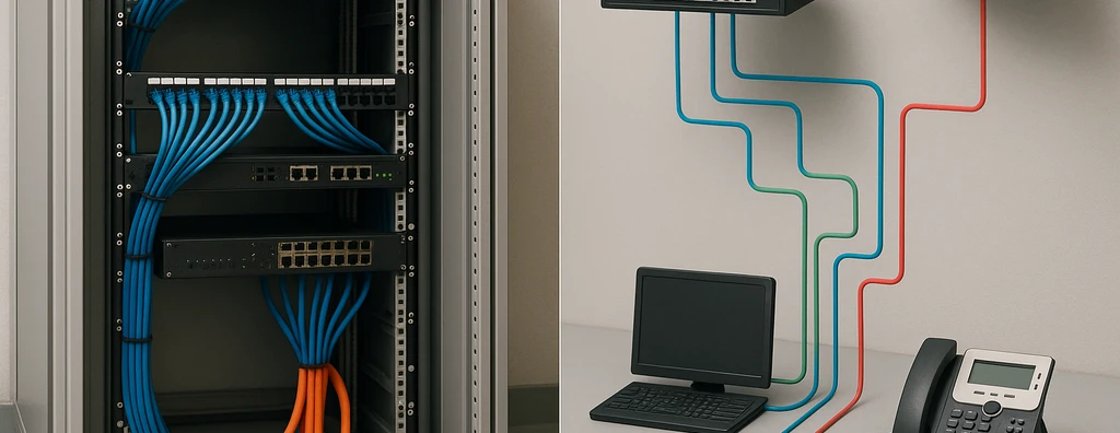
How the same physical network supports multiple logical networks
A well-designed logical network does not correct physical limitations. Uplink capacity, backbone routes, PoE, fiber, racks and documentation must support the planned VLANs, services and policies.
A single access switch may serve corporate users, IP telephony, video surveillance, Wi-Fi, access control and automation. Physically, the devices converge on the same rack and may share uplinks. Logically, each group may belong to a different VLAN and security policy.
The diagram shows why “there is a link” does not mean “there is connectivity.” The port may be electrically active while the device is still assigned to the wrong VLAN, has no gateway, has no DHCP or is blocked by policy.
Layer 1, Layer 2 and Layer 3: where does one end and another begin?
In operations, the boundary between physical and logical functions is often addressed through the first three layers of the OSI model.
Layer 1: medium and signal
The physical layer handles bit transmission. Recurring problems include loss of link, loss of synchronization, physical errors, inadequate optical power, poor termination and incompatible negotiation when the interface depends on medium quality.
Layer 2: Ethernet and the local domain
Layer 2 handles Ethernet frames, MAC addresses, VLANs, trunks, aggregation and loop-prevention mechanisms. A link may be “up” at Layer 1 and still fail at Layer 2 because the VLAN is not allowed on the trunk, the LAG is inconsistent or a spanning-tree protocol is blocking the path.
Layer 3: addressing and routing
Layer 3 introduces IP addresses, subnets, gateways and routes between networks. A host may reach devices on the same VLAN and still be unable to access another subnet because of a missing route, an incorrect gateway or a firewall policy.
This decomposition creates a diagnostic sequence: prove the medium, prove local adjacency, and only then analyze the IP path and policies.
An active physical link does not mean functional communication
A port indicator confirms only part of the problem. It shows that some link condition exists between interfaces, but it does not validate cabling category, performance margin, VLAN, IP, gateway, DNS, ACL, uplink capacity or the application.
Likewise, a successful ping proves only a specific IP connectivity condition at that moment. It does not certify the cabling, prove the absence of Layer 1 errors or validate that the architecture can support production load.
In technical acceptance, each layer requires its own evidence.
Physical topology vs. logical topology
Physical topology describes where the links actually are. In a corporate network, workstations may connect in a star to access switches, with optical uplinks to a core and two physical paths between buildings.
Logical topology describes how traffic is organized. Over the same physical star there may be dozens of VLANs, management networks, VRFs, routing paths, firewall policies and services with different requirements.
Correct documentation must present both views. A single diagram trying to represent every cable, VLAN, IP address and policy at the same time usually becomes illegible and difficult to maintain.
A VLAN is logical, but depends on physical ports and links
VLANs segment Layer 2 domains and allow functions to be separated over the same switching infrastructure. Configuration must remain consistent from the access port through trunks and routing points.
Common problems include:
- access port assigned to the wrong VLAN;
- VLAN not created on an intermediate switch;
- VLAN not allowed on the trunk;
- inconsistent native VLAN;
- different configuration among members of an aggregation;
- physical patch change without updating the logical port;
- documentation not updated after an operational change.
The last case demonstrates the interdependence: a simple patch-cord move may physically connect the user to a port with a different logical configuration.
IP addressing and subnets
The addressing plan defines how hosts and services are organized at Layer 3. It should consider capacity, growth, summarization, location, function, security and operational simplicity.
Assigning addresses randomly creates networks that are difficult to diagnose. In large environments, documentation should relate VLAN, subnet, gateway, DHCP, reservations, static addresses, function and location.
IP conflicts, incorrect masks and wrong gateways produce symptoms that are often mistaken for physical defects because connectivity may work partially or intermittently.
Access, distribution and core switches
Physical and logical architecture is commonly organized into functional layers.
Access connects end devices and concentrates functions such as PoE, access VLANs, authentication and edge policies. Distribution, where present, aggregates access switches and creates control, routing and redundancy boundaries. The core provides high-capacity, low-complexity transport among large network blocks.
In smaller networks, functions may be combined in a collapsed-core architecture. The decision depends on scale, availability, density, number of locations, capacity, operations and criticality — not on an obligation to use three separate physical layers.
Physical redundancy vs. logical redundancy
Having two links drawn on a diagram does not guarantee resilience. If both fibers run through the same cable tray, enter through the same shaft, terminate on the same switch or depend on the same power source, the failure domain remains shared.
Physical redundancy must eliminate relevant single points of failure: routes, fibers, equipment, power supplies, rooms and power feeds when justified by the availability requirement.
Logical redundancy must determine how paths will be used and how recovery will occur: LACP, spanning-tree protocols, dynamic routing, first-hop redundancy and other mechanisms according to the architecture.
The design must analyze both perspectives together. Logical redundancy over physically common infrastructure may create only the appearance of resilience.

Link aggregation and LACP
Link Aggregation combines physical interfaces into one logical interface, increasing aggregate capacity and providing redundancy according to the architecture. LACP negotiates and maintains the group between compatible devices.
Two cautions are essential. First, the capacity of an individual flow may remain limited by the hashing policy and by a single member interface; “4 × 10 Gb/s” does not mean a single flow will automatically use 40 Gb/s. Second, group members must be consistent in speed, VLANs and operational parameters.
LACP failures may leave some paths active and produce intermittent symptoms that are difficult to reproduce.
Spanning Tree and Layer 2 loops
Physical redundancy in Ethernet creates the possibility of loops when parallel paths exist. Spanning Tree family protocols control these topologies by blocking or forwarding paths according to the calculated logical tree.
A loop may cause a broadcast storm, MAC-table instability and widespread loss of communication. The correct response is not to eliminate all redundancy, but to design it and configure coherent control mechanisms.
During troubleshooting, topology changes, blocked ports and reconvergence events should be correlated with the time of the failure.
Routing and logical paths
Routing selects paths between subnets. In simple networks, a few static routes may be sufficient; in larger or redundant environments, dynamic protocols allow adaptation to failures and topology changes.
The choice must consider convergence time, operational complexity, routing domain, policy, team capability and availability requirements. Adding protocols without need increases the error surface and operational difficulty.
An alternate logical route also depends on available physical capacity. During a failure, the remaining path must support the diverted load.
Logical networks and security
Segmentation is an architectural mechanism, but a VLAN should not be treated in isolation as a sufficient security barrier. Communication between segments must be controlled through policies, firewalls, ACLs, authentication and mechanisms appropriate to the risk.
At the edge, 802.1X and NAC solutions can associate identity and policy with network access. In parallel, the physical layer must protect racks, rooms and ports against unauthorized access or improper changes.
Network security is therefore multilayered: no logical configuration can fully compensate for unrestricted physical access to critical infrastructure.
PoE: physical power, logical management
Power over Ethernet clearly illustrates layer integration. Power travels over physical cabling, while managed switches can provide information on consumption, class, status and power budget.
A camera may lose power because of a cable problem, connector issue, required power, switch budget or configuration. Diagnosis must assess both the PoE electrical chain and the logical state of the port.
In design, data and power must be sized together.
Wi-Fi also depends on physical and logical networks
Even in predominantly wireless environments, access points depend on cabling, PoE, switches, uplinks, VLANs, DHCP, routing and policies. Radio adds another physical layer — RF — but does not eliminate wired infrastructure.
A problem perceived as “bad Wi-Fi” may originate in RF channel planning, interference, access-point cabling, insufficient PoE, a saturated uplink, VLAN, DHCP or authentication. The layered method remains valid.
How to document physical and logical networks
Documentation should separate views so that it remains useful.
Physical documents
- outlet and pathway drawings;
- rack diagrams;
- patch-panel and port maps;
- copper and fiber backbone;
- fiber and distribution-panel identification;
- redundant routes;
- certification reports;
- infrastructure As-Built documentation.
Logical documents
- L2 and L3 diagrams;
- VLAN table;
- IP addressing plan;
- gateways and SVI interfaces;
- inter-segment communication matrix;
- routes and protocols;
- firewall/ACL policies according to scope;
- DHCP/DNS services and dependencies;
- naming and management conventions.
Relationship between the two views
The documents must share identifiers. Switch SW-01 in the logical diagram must correspond to equipment SW-01 in the physical rack; port Gi1/0/24 must be traceable to the patch panel, outlet and device when necessary.
This traceability reduces diagnostic time and prevents physical and logical documentation from evolving into incompatible versions.
Troubleshooting: how to separate a physical failure from a logical failure
An efficient sequence avoids premature assumptions.
- Define the exact symptom and scope: one host, one room, one VLAN, one switch or the entire network.
- Confirm power, physical condition and link state of the interfaces.
- Check error counters, speed, duplex and transceivers.
- Test or certify the link when there is physical evidence.
- Validate the access VLAN, trunk and Layer 2 state.
- Check address, mask, gateway, ARP/ND and DHCP.
- Test the IP path and routing tables.
- Evaluate ACLs, firewalls, authentication and dependent services.
- Correlate the incident with recent changes and convergence events.
- Record the root cause and update documentation.
The order may vary by case, but the principle remains constant: every hypothesis requires evidence.
Symptom matrix: physical or logical?
| Symptom | Physical hypotheses | Logical hypotheses |
| link down | cable, connector, port, transceiver, power | port administratively disabled |
| link up without IP | medium probably functional | DHCP, VLAN, authentication, host configuration |
| local communication without internet | uplink/physical port should also be checked | gateway, route, NAT, firewall, DNS |
| dropouts under load | link margin, fiber, PoE, physical errors | congestion, QoS, loop, insufficient capacity |
| only one VLAN fails | physical trunk may be intact | VLAN missing/blocked, SVI, ACL, routing |
| several switches fail together | backbone, power or common physical domain | redundancy protocol, loop, core failure |
| camera restarts | PoE, cable, connector, temperature | PoE policy, firmware/configuration |
The matrix does not replace testing; it organizes hypotheses and helps avoid indiscriminate component replacement.
Example 1: broken fiber vs. missing route
Imagine two buildings interconnected by fiber. All services in the remote building become unavailable.
If the transceiver loses optical signal and the interface goes down, the cause is probably in the physical chain: fiber, distribution panel, patch cord, splice, connector, module or cable route. If the link remains active and local adjacency exists, but remote networks cannot be reached, the investigation should move to routing, gateway, policies and convergence.
Where redundancy exists, it is also necessary to determine why the alternate path did not take over. The cause may be physical — both routes share the same break — or logical — the protocol did not converge as expected.
Example 2: user changes desks and loses access
The workstation was working, was moved to another outlet and then could access only part of the resources.
The first hypothesis may be cabling, but if the link is stable and the physical test passes, the new port configuration should be compared with the previous one. The outlet may terminate on a port configured for another VLAN or with a different authentication policy.
This example shows why physical changes require configuration management and documentation.
Example 3: intermittent network after expansion
After a new switch is installed, users report slowdowns and random communication loss. Individual links pass testing.
Logical analysis may reveal a Layer 2 loop, trunk inconsistency, incomplete LACP or spanning-tree behavior. There may also be an uplink bottleneck: the expansion added traffic without increasing aggregation capacity.
The design must evaluate not only the number of ports, but also traffic flow and failure domains.
Performance: the bottleneck may move between layers
An access network with 1 Gb/s links does not mean one hundred users have 100 Gb/s available simultaneously. Traffic converges on uplinks, the core, firewalls, servers and WAN links.
Likewise, increasing an uplink to 10 or 25 Gb/s does not solve horizontal cabling with errors or storage that cannot deliver the application. Performance is end-to-end.
Engineering must identify where oversubscription is acceptable, which flows are critical, how aggregation occurs and what margin should exist for growth and failures.
Redundancy must be tested, not assumed
High-availability designs require planned failure testing. The behavior when an uplink, switch, route or power supply becomes unavailable must be verified.
The test measures more than whether service “came back.” It may assess convergence time, session loss, capacity of the remaining path, generated alarms, application behavior and operational clarity for the team.
Without testing, redundancy exists only on the drawing.
Integrated physical and logical network design
A robust design starts with business and operational requirements: users, applications, IP systems, criticality, growth, security, mobility, availability and building conditions.
Then the following are coordinated:
- physical and logical survey of the existing environment;
- network topology and hierarchy;
- access and uplink capacity;
- backbone architecture;
- addressing plan and VLANs;
- PoE requirements;
- Wi-Fi, video surveillance, access control and automation;
- physical and logical redundancy;
- security and segmentation;
- testing, commissioning and acceptance criteria;
- documentation and As-Built.
Selecting switches before defining the architecture usually reverses the engineering sequence.
Retrofit: physical and logical baseline
In existing environments, a physical and logical baseline reduces change risk. Inventorying links, assets, VLANs, IP addresses and dependencies makes it possible to discover what must be corrected before migration.
In brownfield environments, the organization must know what actually exists before making changes. Old drawings, IP spreadsheets and saved configurations may differ from field conditions.
Due Diligence can create a baseline by inventorying racks, switches, ports, links, fibers, VLANs, subnets, routes, capacity, utilization and documentation. This technical snapshot makes it possible to classify risks and plan migration without relying on assumptions.
It also prevents replacement of healthy physical infrastructure when the dominant problem is logical architecture — or network reconfiguration when the physical medium is already degraded.
Procurement: specify function, capacity and interoperability
Terms of Reference and specifications must define verifiable requirements: number and type of ports, speeds, PoE, uplinks, redundancy, protocols, management capabilities, capacity, optical interfaces, compatibility, security and documentation.
Selection should not turn one manufacturer’s attribute list into a specification without justification. The objective is to ensure performance and interoperability within the designed architecture.
The same logic applies to cabling: nominal category alone does not define technical equivalence of the system.
Inspection and commissioning
Inspection verifies that implementation preserves the design. Changes to ports, VLANs, routes, transceiver models, fiber paths or equipment positions must be controlled because they may change final behavior.
Commissioning should combine physical and logical evidence, for example:
- certification of copper links;
- fiber testing and loss validation;
- verification of interfaces and transceivers;
- testing of VLANs and trunks;
- validation of addressing and DHCP;
- routing and policy tests;
- redundancy and recovery tests;
- PoE verification under load;
- monitoring and alarm tests;
- verification of final documentation.
Accepting only “it pings” or only “the cable passed certification” leaves a relevant part of the solution unvalidated.
Changes and configuration management
Networks evolve continuously. New users, cameras, access points, servers and services require physical and logical changes.
Change management should record the previous state, planned change, impact, window, rollback method and documentation update. In critical infrastructure, this reduces outages caused by small changes that appear isolated.
As-Built documentation is not produced once and forgotten; it must support operational management.
Final considerations
Physical and logical networks are different representations of a single operational infrastructure. The first establishes the real paths; the second organizes communication, security, segmentation and recovery over those paths.
The best architecture is not the one with the most redundancy or the most protocols, but the one that meets requirements with understood failure domains, sufficient capacity, controllable configuration, traceable documentation and tests that prove the expected behavior.
In design, retrofit and troubleshooting, separating physical and logical layers helps us think. Integrating them is what allows us to solve the system.
Redundancy, segmentation and performance must be demonstrated through testing. Commissioning integrates evidence from cabling, assets, protocols, failover and final documentation.
Technical references
[1] INSTITUTE OF ELECTRICAL AND ELECTRONICS ENGINEERS. IEEE 802.3 Ethernet Working Group. Available at: https://www.ieee802.org/3/
[2] INSTITUTE OF ELECTRICAL AND ELECTRONICS ENGINEERS. IEEE P802.1Q — Bridges and Bridged Networks. Available at: https://standards.ieee.org/ieee/802.1Q/11285/
[3] BRAZILIAN ASSOCIATION OF TECHNICAL STANDARDS. ABNT NBR 14565:2019 — Structured cabling for commercial buildings. Available at: https://www.abntcatalogo.com.br/
[4] INTERNATIONAL ORGANIZATION FOR STANDARDIZATION; INTERNATIONAL ELECTROTECHNICAL COMMISSION. ISO/IEC 11801-1:2017 — Information technology — Generic cabling for customer premises — Part 1: General requirements. Available at: https://www.iso.org/standard/66182.html
[5] ISO; IEC. ISO/IEC 11801-1:2017/Amd 1:2025 — Amendment 1. Available at: https://www.iso.org/standard/93480.html
Frequently asked questions
The physical network is the material infrastructure — cables, fibers, racks, ports and paths. The logical network organizes communication over that foundation using VLANs, addressing, subnets, routing, policies and redundancy mechanisms.
No. The link proves only a basic physical condition between interfaces. VLAN, DHCP, IP, gateway, routing, policy or capacity problems may still exist.
No. A VLAN is a logical Layer 2 construct. It does, however, depend on physical ports, switches and links to carry the associated frames.
Diagnostics should first validate link state, interface errors and the physical medium; then Layer 2, VLANs and trunks; then addressing, gateway, routing and policies. Each hypothesis must be confirmed by evidence.
No. Failover protocols can use only paths that actually exist. Two links sharing the same physical route, switch, room or power source may remain subject to the same single point of failure.
Not necessarily. Capacity is aggregated across multiple flows according to the distribution policy; an individual flow may remain limited to the capacity of one member.
It is relevant in Layer 2 Ethernet topologies where redundant paths and loops may exist. An architecture may use other approaches, but redundancy must always have a coherent control mechanism.
The documentation should make it possible to trace equipment, racks, links and ports as well as VLANs, subnets, gateways, routes and relevant policies, using consistent identifiers between the physical and logical views.
Complementary technical materials
Related solutions
Related services
- Technical Due Diligence
- Structured Cabling Design
- Technical Testing
- Commissioning
- Engineering As-Built Documentation
Key content on this topic
- Physical Network: Components, Physical Layer, Failures and Troubleshooting
- Network Infrastructure: Complete Guide
- Network Design: Stages, Architecture and Technical Documentation
