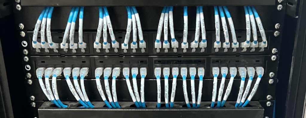
Understand what a physical network is, its relationship with the OSI physical layer, components, cabling, fiber, PoE, failures, certification, troubleshooting, documentation, and retrofit.
Check it out!
The physical network is the set of media, interfaces, pathways, spaces, and components that make signal transport between devices possible. In Ethernet networks, this includes copper or fiber-optic cables, connectors, patch panels, fiber distribution frames, racks, outlets, patch cords, transceivers, physical ports, cable trays, conduits, and the infrastructure that protects and organizes these elements.
The term is often confused with the physical layer of the OSI model. Layer 1 defines how bits are represented and transmitted through electrical, optical, or radio-frequency signals; the physical network, in engineering use, is broader and includes the material infrastructure that allows this layer to operate predictably, verifiably, maintainably, and scalably.
A physical failure can exist even when the logical configuration is correct. Likewise, a link can be electrically sound while a VLAN, addressing, routing, or policy problem still exists. For this reason, network troubleshooting requires separating physical evidence from logical evidence.
What Is a Physical Network?
The physical network is the material foundation of communication. It connects endpoints and active network equipment through real links and pathways, with requirements for distance, performance, mechanical protection, electromagnetic compatibility, identification, and documentation.
In corporate infrastructure, the physical network is normally organized into horizontal cabling, backbone, telecommunications rooms or closets, distributors, racks, consolidation points where applicable, telecommunications outlets, and physical pathways. In larger environments, copper and fiber optics coexist: copper serves most horizontal outlets and PoE devices; fiber concentrates backbone interconnections, longer distances, high capacity, and situations where galvanic isolation is desirable.
The physical network should not be treated as a collection of cables. Performance is systemic: cable, connectivity, patch cords, installation method, pathways, environment, active interfaces, and documentation must be compatible with one another.

Physical Network, Physical Layer, and Network Infrastructure Are Not Synonyms
The three concepts are related, but their scopes are different.
| Concept | Main scope | Examples |
| Physical layer | Bit transmission and characteristics of media/interfaces | signaling, physical encoding, connectors, electrical and optical characteristics |
| Physical network | Materialization of links and interconnections | cables, fibers, patch panels, fiber distribution frames, racks, transceivers, routes |
| Network infrastructure | Physical, active, logical, and operational set | physical network + switches + routers + VLANs + addressing + monitoring |
This distinction avoids a common troubleshooting error: calling every outage a “physical network problem.” An administratively disabled port, an incorrect VLAN, or a missing route are real network problems, but they are not defects of the physical medium.
What Makes Up the Physical Network?
Twisted-Pair Copper Cables
In commercial buildings and corporate networks, balanced twisted pair is the most common medium in horizontal cabling. Categories such as Cat5e, Cat6, and Cat6A have different performance requirements and should be analyzed as cabling systems, not merely as markings printed on a cable jacket.
A higher-category link is not achieved by replacing the cable alone. Patch panels, connectors, outlets, patch cords, and the termination method must preserve the intended performance. Mixing components from incompatible sources, categories, or constructions can reduce margin and make system warranty more difficult.
Optical Fiber
Optical fiber carries signals as light, offers high capacity, low attenuation compared with long metallic links, and is immune to electromagnetic coupling in the transmission medium itself. It is common in building backbones, campuses, data centers, industrial areas, and interbuilding links.
Engineering must define fiber type, fiber count, connectivity, fiber distribution frames, cords, transceivers, optical budget, spare capacity, bend radius, installation method, and test criteria. “Use fiber” does not eliminate the need for design.
Connectors, Outlets, and Connection Hardware
Connectors and connection hardware are controlled discontinuity points in a link. In copper, small changes in geometry and untwisting near terminations affect performance. In fiber, cleanliness, connectorization quality, polish, bending, and insertion loss are decisive.
For this reason, termination inspection and certification must consider the complete assembly, not only electrical or optical continuity.
Patch Panels, Fiber Distribution Frames, and Distributors
Patch panels and fiber distribution frames organize connectivity and allow operation, maintenance, and changes without turning permanent cabling into a set of improvised branches. Well-defined distributors also facilitate identification, segregation, and traceability.
An organized rack is not merely an aesthetic concern. Organization reduces mechanical stress on connectors, improves ventilation, reduces patching errors, and speeds troubleshooting.
Racks and Telecommunications Cabinets
Racks concentrate active equipment, passive terminations, organizers, and power elements. The design should consider size, spare rack units, depth, heat dissipation, power, grounding/equipotential bonding, front and rear access, vertical and horizontal organization, expansion, and physical security.
An overcrowded cabinet can create problems that appear as “network failures”: tensioned patch cords, insufficient ventilation, inaccessible ports, inspection difficulty, and incorrect patching.
Dry Infrastructure: Pathways and Spaces
Cable trays, ladder racks, conduits, shafts, boxes, and other pathways are part of physical-network reliability. A technically suitable cable can have its service life and performance compromised by excessive pulling force, crushing, inadequate bend radius, routes exposed to water, saturated conduits, or improper proximity to disturbance sources.
The infrastructure should be sized for current occupancy and expansion. Reserving capacity does not mean oversizing without criteria; it means preventing the first expansion from requiring dismantling of the existing installation.
Physical Interfaces and Active Equipment
The physical network also terminates at active interfaces: Ethernet ports, NICs, SFP/SFP+/SFP28 modules, and other transceivers. These elements provide conversion between the physical medium and upper-layer functions.
Switches and routers do not belong exclusively to the physical layer — they perform Layer 2 and Layer 3 functions — but their physical interfaces are part of the actual communication chain. A failed port, incompatible transceiver, reversed fiber pair, or inappropriate speed negotiation can produce symptoms similar to cabling defects.
This is one reason why infrastructure troubleshooting should combine measurements of the medium with port-status readings, error counters, and operational behavior.
Copper vs. Fiber vs. Wireless From a Physical Perspective
Wireless also has a physical layer, but it is not “cabling.” Transmission occurs through radio frequency and the medium is electromagnetic space. Even so, an access point depends on wired physical infrastructure for uplink and often for PoE power.
In modern corporate networks, wired and wireless are therefore complementary. The wired network normally supports access points, IP cameras, IP telephony, automation devices, fixed workstations, servers, and uplinks; Wi-Fi serves mobility and density of radio-capable devices.
Cabling Categories and Ethernet Applications
The cabling category describes passive-system performance; the Ethernet application describes the communication that will use that medium. These concepts should not be confused.
| System | Reference frequency | Typical applications |
| Cat5e | 100 MHz | 1000BASE-T up to the channel’s normative limits |
| Cat6 | 250 MHz | 1000BASE-T; 10GBASE-T under conditions and at reduced distances |
| Cat6A | 500 MHz | 10GBASE-T in channels up to 100 m according to application and design |
The choice should not be based only on the switch’s current speed. Building service life, PoE, density, expansion, replacement cost, and performance margin also influence the decision.
Physical Topology: How Links Are Organized
A reliable physical network starts with design: topology, outlets, backbone, racks, pathways, PoE, environment, and acceptance criteria must be defined before installation.
In corporate networks, the most common physical topology is the hierarchical star: endpoints connect to access switches; those switches connect to distribution or core layers according to network scale.
This architecture facilitates expansion, fault isolation, and administration. The logical network can create multiple VLANs over the same physical topology, but all of them still depend on the capacity and availability of the actual links.
Power over Ethernet Changes the Physical Design
PoE carries data and power over the same balanced cabling and has turned the physical network into a power-delivery infrastructure for IP cameras, access points, phones, controllers, and IoT devices.
The design must consider device power demand, PoE class, total switch power budget, channel losses, conductor gauge, temperature, cable bundling, connectivity, and heat dissipation. A link can carry data correctly and still have a power-delivery problem under load.
In a retrofit, it is inappropriate to assume that “if it works with a laptop, it will work with a PoE device.” The assessment must reflect the actual application.
Electromagnetic Compatibility and Equipotential Bonding
Balanced twisted pairs provide good rejection of disturbances when the system is properly designed and installed. However, proximity to drives, motors, feeders, busbars, welding equipment, transformers, and other harsh environments may require additional analysis.
Shielding is not an automatic fix. The use of F/UTP, U/FTP, S/FTP, or other constructions must be coordinated with compatible connectors, continuity, and equipotential bonding. A poorly integrated shielded cable can increase cost without delivering a controlled benefit.
ABNT NBR 17040 addresses equipotential bonding of telecommunications infrastructure and reinforces that racks, busbars, shields, and metallic elements must be coherently integrated into the building’s equipotential-bonding system.
Physical Environment: Temperature, Humidity, Dust, and Mechanical Stress
The physical network exists in a real environment. Temperature, humidity, water, chemical agents, vibration, dust, UV exposure, and mechanical stress affect materials and connections.
In industrial areas, environmental classification should not be reduced to “use industrial cable.” Mechanical, ingress, climatic/chemical, and electromagnetic conditions must be assessed, and pathways, protection, enclosures, and transition points between environments must be defined.
Main Physical Network Failures
Termination and Wire-Map Errors
Opens, shorts, crossed pairs, reversals, and split pairs can cause anything from complete loss of link to unstable operation. A split pair is especially deceptive because continuity may appear correct while pair balance is compromised.
Excessive Length
Length beyond the standard’s allowance increases loss and may compromise margin. Channel limits must consider permanent cabling and cords, not just approximate plan distance.
Insertion Loss and Degraded Connections
Cables, connectors, improper splices, and poor terminations increase losses. Oxidation, crushing, and mechanical damage can also degrade transmission.
Crosstalk and Return Loss
Pair geometry, untwisting, connector quality, bends, and discontinuities affect NEXT, return loss, and other performance parameters. These phenomena cannot be diagnosed by a simple continuity test.
Inadequate Patch Cords
Improvised, excessively long, damaged, or performance-incompatible patch cords can reduce channel margin. Rack administration should use appropriate lengths and routes that do not impose stress on connectors.
Optical Failures
In fiber, recurring causes include contaminated connectors, macrobends, high-loss splices, damaged connectors, incompatible transceivers, and insufficient optical budget.
Power and PoE Problems
PoE device outages can result from insufficient switch power budget, peak power, heating, connectors, or degraded channels. The existence of an Ethernet link does not prove that power delivery is adequate.
How to Troubleshoot the Physical Network Without Confusing It With a Logical Problem
When a failure is intermittent, the right test distinguishes a cabling defect, an interface problem, and a logical cause. Continuity alone does not replace certification and technical troubleshooting.
Troubleshooting should start with the symptom and proceed through evidence. Randomly swapping cables can mask the defect and create new problems.
- Record where, when, and on which devices the failure occurs.
- Check physical condition, LEDs, connectors, patch cords, and power.
- Check the port, negotiated speed, and switch error counters.
- Isolate the suspected link and test it with appropriate equipment.
- Compare the result with the specified category and application.
- Correlate failures with PoE load, temperature, electrical switching, or environmental events.
- After validating the physical medium, proceed to VLAN, IP, routing, DNS, DHCP, and policies.
A layered methodology prevents the team from trying to fix configuration when the defect is physical — or replacing cabling when the cause is in the logical network.
Certification, Qualification, and Verification Are Not the Same Thing
A continuity tester checks basic connectivity. A qualifier can assess capability for specific applications. A cabling certifier compares measured parameters with normative limits defined for a category and test configuration.
For project acceptance, the design must state the test method and limit. Permanent Link, Channel, and, where applicable, MPTL represent different configurations and should not be mixed in reports.
Cabling certification also does not replace network commissioning. Certification demonstrates medium performance; commissioning verifies whether the implemented solution operates according to system requirements.
Documentation Is Part of the Physical Network
Infrastructure without identification and As-Built documentation loses operational value. When no one knows which port serves which outlet, which fiber corresponds to which link, or which pathway contains a given cable, every intervention becomes dependent on trial and error.
Documentation should accompany implementation and may include:
- identification of racks, patch panels, fiber distribution frames, ports, and outlets;
- drawings with outlets and routes;
- backbone and topology diagrams;
- link schedule;
- asset and transceiver list;
- certification reports;
- native test files when required;
- change records and final As-Built documentation.
This set reduces maintenance time, supports expansion, and makes acceptance auditable.
Physical Network Retrofit and Due Diligence
In existing installations, the first step should not be to replace everything. A Technical Due Diligence separates reusable assets and links from deficiencies that actually require intervention.
The survey can combine field inspection, document review, rack mapping, sampling or link certification, capacity analysis, obsolescence identification, backbone verification, and continuity-risk assessment.
With technical evidence, retrofit can be prioritized by criticality instead of becoming indiscriminate infrastructure replacement.
Design, Procurement, and Construction Oversight
The design converts requirements into verifiable criteria. The specification should define performance, interfaces, environment, capacity, identification, tests, and deliverables without relying only on commercial brands.
During procurement, technical equivalence must be assessed for the complete system. A cable with the same nominal category does not guarantee equivalence if connectors, certifications, construction, reaction to fire, diameter, or PoE compatibility differ from the requirement.
During construction oversight, materials, cable installation, pathway occupancy, bend radii, rack organization, identification, terminations, test results, and final documentation should be verified.
Physical Security of the Infrastructure
Racks, technical rooms, and backbone pathways support critical services. Physical access control, cabinet locking, key management, protection against accidental intervention, and environmental monitoring are part of network availability.
A robust logical policy does not compensate for an open rack in a public area with accessible ports and patch cords. Security must exist from the physical layers through the logical layers.
When the Physical Network Needs Upgrading
Recurring signs include intermittent failures, undocumented growth, saturated racks, lack of certification, limited backbone capacity, PoE equipment operating at its limits, unidentified outlets, full pathways, nonstandard cables, high rework rates, and changes requiring long outage windows.
In these cases, correction should be managed as an engineering project: survey, diagnosis, baseline definition, prioritization, upgrading design, controlled implementation, testing, and As-Built documentation.
Final Considerations
A physical network is much more than “the cable.” It is the material infrastructure that supports communication and conditions performance, availability, PoE, expansion, maintenance, and troubleshooting capability.
A reliable network results from integration among cabling, fiber, racks, pathways, interfaces, environment, equipotential bonding, certification, and documentation. When this foundation is treated as engineering — not as isolated assembly — the logical layer operates on a predictable and auditable base.
In existing networks, the best decision is not always to replace everything. A structured survey makes it possible to establish a baseline, prioritize risks, and define a technically justified retrofit.
Technical references
[1] BRAZILIAN ASSOCIATION OF TECHNICAL STANDARDS. ABNT NBR 14565:2019 — Structured cabling for commercial buildings. Available at: https://www.abntcatalogo.com.br/
[2] BRAZILIAN ASSOCIATION OF TECHNICAL STANDARDS. ABNT NBR 17040 — Equipotential bonding of telecommunications infrastructure. Available at: https://www.abntcatalogo.com.br/
[3] INTERNATIONAL ORGANIZATION FOR STANDARDIZATION; INTERNATIONAL ELECTROTECHNICAL COMMISSION. ISO/IEC 11801-1:2017 — Information technology — Generic cabling for customer premises — Part 1: General requirements. Available at: https://www.iso.org/standard/66182.html
[4] ISO; IEC. ISO/IEC 11801-1:2017/Amd 1:2025 — Amendment 1. Available at: https://www.iso.org/standard/93480.html
[5] TELECOMMUNICATIONS INDUSTRY ASSOCIATION. ANSI/TIA-568.2-E — Balanced Twisted-Pair Telecommunications Cabling and Components Standard, 2024. Available at: https://tiaonline.org/standardannouncement/tia-publishes-new-standards-ansi-tia-568-2-e-and-ansi-tia-568-5-1/
[6] IEEE 802.3 ETHERNET WORKING GROUP. Ethernet standards and activities. Available at: https://www.ieee802.org/3/
Frequently asked questions
Not exactly. The physical layer is Layer 1 of the OSI model and addresses bit transmission and media characteristics. In engineering use, the physical network also includes the material infrastructure that implements links: cables, fibers, connectors, racks, patch panels, fiber distribution frames, pathways, and interfaces.
A switch performs Layer 2 functions and, in some models, Layer 3 functions. However, its ports and transceivers are physical communication interfaces. The equipment therefore participates in network infrastructure even though it is not exclusively a physical-layer component.
Troubleshooting should start with link state, connectors, port status, error counters, and link tests. If the physical medium is sound, proceed to VLAN, addressing, routing, DNS, DHCP, and policy checks.
No. Continuity identifies basic connectivity problems. Certification measures performance parameters and compares the link against normative limits defined for the category and test configuration.
Yes. A link can establish communication while still having insufficient power, excessive loss, heating, or connectivity problems under PoE load.
Fiber is indicated for backbones, longer distances, high capacity, interbuilding links, and situations where electromagnetic immunity and galvanic isolation are relevant advantages.
Because they make it possible to locate links, ports, fibers, and routes, reduce maintenance errors, speed troubleshooting, and make expansions and technical acceptance traceable.
Not necessarily. A Technical Due Diligence can identify which links and assets still meet requirements and which points require upgrading, enabling a criticality-based retrofit.
Additional technical materials
Related solutions
Related services
- Projeto de Structured Cabling
- Technical Testing and Verification
- Technical Due Diligence
- Engineering As-Built
Main content on the topic
- Network Infrastructure: complete guide
- Network Cabling: types, components, standards, and design
- Network Design: stages, architecture, and technical documentation
