
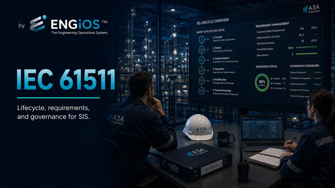
Understand IEC 61511, Parts 1, 2 and 3, the Safety Lifecycle, Functional Safety Management, SRS, SIL, verification, validation, operation, and MOC.
Check it out!
IEC 61511 is the main international series for Functional Safety of Safety Instrumented Systems (SIS) in the process industry. It defines how hazards and risks are converted into requirements for instrumented functions, and how those functions are specified, designed, verified, installed, validated, operated, maintained, modified, and ultimately decommissioned. Its central approach is the lifecycle: selecting certified equipment or performing an isolated SIL calculation is not enough. It is necessary to demonstrate that each phase preserves the safety requirements and that responsibilities, competence, documentation, verification, and management of change remain controlled. In 2026, IEC also markets the “IEC 61511:2026 SER” package, but this does not represent a new technical edition of every part: the normative core remains IEC 61511-1:2016+A1:2017, IEC 61511-2:2016, and IEC 61511-3:2016, supplemented by technical reports in the series.
What IEC 61511 Is
IEC 61511 addresses Functional Safety through Safety Instrumented Systems in the process sector. Its scope extends from hazard assessment and definition of safety functions through operation, maintenance, and management of change. Part 1 establishes requirements; Part 2 provides application guidance; and Part 3 provides guidance for determining the required safety integrity levels.
The series is a sector-specific implementation of IEC 61508 for the process industries. While IEC 61508 establishes general principles for safety-related electrical, electronic, and programmable electronic systems, IEC 61511 translates those foundations into the context of process plants, operators, integrators, owners, and suppliers.
The Standard Is Not Only About Safety PLCs
Reducing IEC 61511 to a Safety PLC standard misses its most important element: the complete system and its management. An instrumented function spans sensors, the logic solver, final elements, installations, application software, power supply, communications, testing, operation, and maintenance.
Function performance depends on both architecture and lifecycle quality. A certified platform does not compensate for an incomplete SRS, an unsuitable transmitter, a valve that fails to close, a low-coverage proof test, or uncontrolled logic changes.
How the IEC 61511 Series Is Structured
The series has parts with distinct purposes. Understanding this structure prevents guidance from being treated as normative requirements and prevents Part 3 from being used as though it prescribed a universal SIL for each application.
| Document | Main role |
| IEC 61511-1:2016+A1:2017 | Framework, system, hardware, and application programming requirements |
| IEC 61511-2:2016 | Guidelines for applying Part 1 |
| IEC 61511-3:2016 | Guidance for determining the required SIL |
| IEC TR 61511-0:2018 | Overview of the series and Functional Safety in the process sector |
| IEC TR 61511-4:2020 | Explanations and rationale for changes between editions of Part 1 |
What IEC 61511:2026 SER Means
In July 2026, the IEC catalog began listing IEC 61511:2026 SER — ALL PARTS. This item is a commercial series package that groups existing documents, including IEC TR 61511-0:2018, IEC 61511-1:2016+A1:2017, IEC 61511-2:2016, IEC 61511-3:2016, and IEC TR 61511-4:2020.
Therefore, it is not technically correct to interpret “2026 SER” as a third edition of normative content published in 2026. Engineering specifications and documents should reference the part and edition that actually apply.
Functional Safety in the Process Industry
Functional Safety is the portion of overall safety that depends on safety-related systems functioning correctly in response to their inputs. In the IEC 61511 context, the focus is on Safety Instrumented Functions implemented to reduce process risk.
This distinguishes the discipline from purely mechanical safety, passive protection, occupational safety, or administrative procedures. Those other layers may be essential, but IEC 61511 specifically addresses the use of instrumented functions and their contribution to risk reduction.
From Hazard to Functional Safety Requirement
The lifecycle begins before detailed SIS design. The process must be understood, hazards identified, and scenarios, consequences, initiating events, and existing protection layers evaluated. HAZID and HAZOP are common techniques for developing scenarios and deviations; LOPA can be used to assess independent layers and quantify the additional risk reduction required.
The standard does not replace the risk-engineering process. It requires functional and integrity requirements to be grounded in hazard and risk assessment.
Safety Lifecycle
The Safety Lifecycle organizes the activities required so that Functional Safety requirements are not lost during design, procurement, fabrication, implementation, operation, or modification. It is both a technical and a governance structure.
A mature organization establishes gates between phases: a phase advances only when inputs, deliverables, reviews, critical actions, and responsibilities reach acceptable conditions. This reduces the practice of “fixing it later during commissioning,” which is usually expensive and insufficient for systematic requirements.
Early Phases
In the early phases, scope, hazards, risk, required functions, and integrity levels are established. Conceptual decisions made here influence architecture, cost, availability, and maintenance throughout the asset life.
Failure to involve operations and maintenance at this stage can produce SIFs that are technically calculated but difficult to test, maintain, or operate.
Engineering and Implementation
Once requirements are defined, the design must demonstrate that the architecture and implementation can fulfill the functions. This includes hardware, application software, interfaces, power supply, independence, voting, diagnostics, final elements, and testability.
The design must be verified against approved requirements, not verbal expectations.
Operation and Maintenance
Integrity does not end at startup. Test intervals, discovered failures, bypasses, repairs, actual demands, changes, and field data influence future performance. Management must retain evidence that the assumptions used in design remain valid.
Functional Safety Management
Applying IEC 61511 starts with governance: scope, responsibilities, competence, documents, and gates need to be defined before procurement and SIS implementation.
Functional Safety Management establishes the structure of responsibilities, competence, procedures, planning, verifications, assessments, and documentation required to manage the lifecycle.
A statement that an integrator “follows IEC 61511” is not enough. The owner needs to define who is responsible for each activity, which deliverables are required, which approvals are necessary, and how exceptions will be handled.
Functional Safety Plan
A plan can organize:
- lifecycle scope;
- responsibilities by phase and deliverable;
- required competence;
- verification activities;
- Functional Safety Assessments;
- interfaces between contracting parties and suppliers;
- documents and records;
- gate criteria;
- deviation management;
- configuration and version control;
- management of change;
- audits and indicators.
The plan should be proportional to risk and complexity. The objective is not to create bureaucracy, but to eliminate gaps in responsibility.
Competence and Responsibilities
IEC 61511 presumes competence appropriate to the activities. Functional Safety is multidisciplinary: process, instrumentation, automation, reliability, operations, maintenance, software engineering, and risk management may all participate in the same SIF.
Competence must be assessed against the task. A person may be excellent at PLC programming yet lack experience facilitating HAZOP; another may conduct LOPA but not be responsible for detailed hardware calculations.
Independence in Reviews and Assessments
Verification, validation, and Functional Safety Assessment have different objectives. The required degree of independence must be established according to the activity, risk, complexity, and organizational structure.
Using the same person to create requirements, design, implement, and “approve” everything without adequate review concentrates bias and increases systematic-failure risk.
Hazard and Risk Assessment
The hazard and risk assessment must produce enough information to define SIF requirements. The scenario should identify consequence, initiating event, enabling conditions, safeguards, and tolerable risk.
Part 3 of IEC 61511 presents methods and a structure for determining the required SIL, but it does not define that a given application “is SIL 2” by default. SIL results from the risk reduction required for the scenario.
SIL Allocation
After identifying the additional reduction required, it is necessary to decide how that reduction will be distributed among protection layers. A SIF may receive a given integrity requirement when it is part of the risk-reduction solution.
LOPA is frequently used to support this decision, provided IPL criteria, independence, and data are established consistently.
Required SIL Is Not the Platform SIL
SIL determination answers “how much performance is required.” Verification answers “can the proposed design achieve that performance.” These are different problems.
Mixing them leads to misguided procurement, such as selecting a high-capability PLC before determining which functions actually require SIL and which architectures are necessary.
Safety Requirements Specification — SRS
The SRS is the bridge between risk analysis and implementation. It describes the functions, demand conditions, safe states, timing, required integrity, voting, reset, bypass, interfaces, environmental requirements, proof tests, and other necessary characteristics.
A well-developed SRS must be verifiable. Vague statements such as “shut down in a critical condition” do not define the variable, threshold, timing, action, safe state, or reset conditions.
SRS Traceability
Each relevant requirement should have an identifiable origin and destination. A HAZOP scenario may generate a recommendation; LOPA may establish the need for a SIF; the SRS describes the function; cause-and-effect documentation summarizes the logic; software implements it; FAT/SAT verify it; validation demonstrates compliance.
SIS Design
The design must consider the complete SIF. Sensors, logic solver, final elements, and auxiliary resources need to be compatible with the safety requirement and process conditions.
Relevant aspects include architecture, redundancy, common-cause failure, segregation, power supply, diagnostics, environment, response time, bypasses, interfaces with the BPCS, and testability.
Independence Between BPCS and SIS
When the BPCS participates in the initiating event or receives credit in the risk analysis, its relationship with the SIS must be examined carefully. Dependencies may exist in sensors, networks, power, workstations, software, utilities, and maintenance.
Independence does not necessarily mean duplicating every component. It means demonstrating that the safety layer does not lose its ability to act because of the same failures it is intended to mitigate.
Hardware Fault Tolerance and Architecture
Selection of 1oo1, 1oo2, 2oo3, and other architectures should not be habitual. It must consider fault tolerance, diagnostics, availability, common cause, architectural constraints, and safe behavior.
Adding redundancy can reduce some dangerous failures while simultaneously increasing complexity, maintenance, and sources of spurious trips.
Random and Systematic Failures
Functional Safety distinguishes probabilistic hardware problems from systematic failures caused by inadequate specification, design, software, procedures, or management.
PFDavg calculations help assess random failures but do not replace engineering-quality measures required to control systematic failures. An excellent spreadsheet cannot correct a wrong requirement.
Reliability Data
Data used for verification need traceable sources, application conditions, and assumptions. Generic rates copied without understanding the environment, operating mode, diagnostics, or maintenance can produce mathematically precise but technically fragile results.
Manufacturer data, recognized databases, and operating experience may contribute, but their representativeness needs to be assessed.
Proof Test and Test Interval
A proof test reveals hidden dangerous failures not detected by automatic diagnostics. Its interval and coverage affect the calculated performance of the SIF.
The procedure needs to be defined during engineering because an architecture that depends on a test that cannot be performed in operation creates a lifecycle problem. Maintainability must be a design requirement.
Application Software
Programming safety functions requires control of requirements, architecture, coding standards, reviews, testing, versioning, and configuration. Changes must remain traceable.
The discipline differs from conventional programming, where rapid changes may be valued. In a SIS, every change can alter a risk barrier and must undergo appropriate assessment.
Configuration Management
Configuration includes versions of logic, firmware, parameters, libraries, project files, documentation, and backups. It must be possible to know which version is actually in operation and which evidence corresponds to it.
A FAT report can lose practical validity if, after testing, logic or parameters are changed without control and without renewed verification proportional to the impact.
Verification Throughout the Lifecycle
Verification confirms that the output of a given phase meets that phase’s inputs and requirements. It may occur in studies, the SRS, calculations, drawings, software, procedures, and test results.
Early verification reduces cost. Finding an inconsistency in the SRS before programming is far less costly than discovering it during startup.
Functional Safety Assessment — FSA
FSA is a structured assessment of Functional Safety at appropriate points in the lifecycle. The objective is to gain confidence that the necessary activities and evidence have been completed properly before critical decisions.
The assessment should not be reduced to a superficial checklist. It needs to examine risks, requirements, open actions, verification, competence, changes, deviations, and readiness for the next phase.
Functional Safety Audit
Auditing and FSA are not exactly the same activity. Audits verify whether procedures and the management system are implemented and maintained; assessments examine the adequacy of Functional Safety at specific lifecycle stages.
A corporate program may combine both to identify deterioration in discipline before it appears as incidents or failed demands.
FAT Within the IEC 61511 Lifecycle
FAT provides an opportunity to verify hardware and software before installation. It should be driven by the SRS and other approved requirements.
Test cases need to cover normal logic operation, trip conditions, voting, diagnostics, alarms, bypasses, reset, simulated failures, and relevant interfaces. Results should record the version tested.
SAT, Installation, and Pre-commissioning
After installation, cables, grounding, power, instruments, calibration, I/O, networks, final-element actuation, and interfaces need to be verified.
Separating physical inspections, loop checks, and SAT from validation helps identify the nature of deviations and prevents the final test from becoming an unstructured correction of installation work.
Functional Safety Validation
FAT, SAT, and validation must be treated as different stages, each with its own procedure, evidence, and acceptance criteria. Structured commissioning reduces the likelihood that an incomplete installation will be considered ready merely because it is energized.
Validation demonstrates that the final installation complies with the SRS. It should include the actual chain to the extent practicable and verify functional, timing, diagnostic, voting, bypass, and failure-state requirements.
Validation needs a procedure, acceptance criteria, and evidence records. A function that simply “trips” is not automatically validated.
Operation and Maintenance
After startup, the organization needs to perform proof tests, correct failures, manage bypasses, review demands, and maintain documentation. The performance assumed during verification depends on these activities.
Operating history may reveal that demand rates, failure rates, or repair times differ from the assumptions. These data should feed back into risk management.
Bypasses and Overrides
A bypass makes a protection layer partially or fully unavailable. It therefore requires control, authorization, a time limit, justification, compensating measures, and operational visibility.
A large number of permanent bypasses is a sign of deteriorating governance or inadequate architecture.
Management of Change — MOC
Changes to the process, setpoints, instruments, voting, logic, final elements, proof tests, or interfaces can affect Functional Safety. MOC should determine impact before execution.
Approved changes should update the SRS, drawings, software, procedures, training, tests, and As Built documentation as applicable.
Modifications During Operation
The plant needs to distinguish maintenance that restores the original condition from a modification that changes requirements or performance. The latter requires broader engineering assessment.
Replacing a transmitter with an “equivalent” may require review if technology, diagnostics, response time, or reliability data differ from those used in the calculation.
Decommissioning
Removing a SIF from service is also a change in risk. It is necessary to demonstrate why the function is no longer required or which layer replaces its contribution.
Disabling a function because it “never operated” is technically weak justification: safety functions may exist precisely for rare events.
IEC 61511 and Cybersecurity
The current edition of Part 1 recognizes that cybersecurity threats can affect Functional Safety. The lifecycle needs to assess vulnerabilities when exploitation could compromise SIF capability.
Network architecture, access, engineering workstations, backups, patching, removable media, privileged accounts, and supplier management need to be governed together with availability and safety requirements.
IEC 61511 and Human Factors
Human error is not only an operations issue. Requirements, interfaces, maintenance, procedures, and alarms can create conditions that favor failure.
Designs should consider diagnostic capability, clarity of indication, prevention of inadvertent bypass, maintenance ergonomics, and operator response to degraded states.
Brownfield and Legacy Systems
Existing facilities often have incomplete documentation, modified logic, and components without original data. Applying IEC 61511 principles in brownfield environments first requires understanding the actual state.
Field surveys, logic recovery, history reviews, proof tests, As Built documentation, and change analysis are fundamental before concluding that an existing function meets a given performance level.
Grandfathering and Existing Installations
ISA guidance related to IEC 61511 discusses treatment of existing SIS. The fact that an installation is old does not eliminate the need to demonstrate safe operation, maintenance, procedures, and adequate management.
The strategy should be based on technical assessment and risk, not on assuming automatic compliance because of age or because the system was accepted in the past.
Procurement Aligned with the Lifecycle
Procurement aligned with IEC 61511 starts with responsibilities and deliverables. The integrator should know which requirements it receives, what it must produce, how it will be verified, and which evidence is necessary for acceptance.
The commercial scope should include documentation, data, testing, software, training, licenses, backups, and support, not only panels and controllers.
Responsibility Matrix
When the owner, designer, EPC contractor, integrator, manufacturer, and commissioning company participate, a clear matrix prevents gaps. Activities such as SIL determination, SRS, calculations, FAT, validation, and proof testing need defined responsible parties, approvers, and interfaces.
Technical responsibility should not be inferred merely because a supplier delivers equipment.
Owner’s Engineering in IEC 61511
When integrators, manufacturers, and different disciplines participate, Owner’s Engineering preserves traceability between risk, requirements, design, deviations, and acceptance on behalf of the owner.
Owner’s Engineering can represent the owner in lifecycle governance, review requirements, coordinate interfaces, follow suppliers, control actions, and support decision gates.
This role is especially useful when the owner wants to preserve independence from the integrator and ensure that acceptance considers lifecycle requirements, not only physical delivery.
Project Assurance and Independent Review
Independent review can assess whether requirements, architecture, documentation, and testing support the decision to advance. Its purpose is not to replace the designer’s responsibility, but to create an additional layer of technical confidence.
In complex projects, Assurance can be applied at gates such as HAZOP/LOPA completion, SRS approval, release for fabrication, FAT completion, and startup readiness.
Corporate Standardization
Companies with multiple plants gain consistency by creating Functional Safety standards: SRS templates, SIL criteria, LOPA formats, bypass philosophy, proof-test procedures, nomenclature, FAT checklists, and MOC rules.
Standardization reduces variability but does not eliminate application-specific analysis. A plant may require exceptions justified by process, technology, or risk.
Governance Indicators
Indicators can provide early warning of lifecycle degradation. Examples include:
- overdue proof tests;
- SIFs in bypass;
- backlog of HAZOP/LOPA actions;
- changes without documentary closure;
- failures detected during testing;
- spurious trips;
- actual demands and successful operation;
- validation outstanding items;
- overdue As Built documentation;
- temporary deviations beyond their deadline.
Indicators must drive decisions. A metric without an owner and action threshold becomes merely a report.
How to Structure an IEC 61511 Gap Audit
A consulting audit can start with the management system and then follow technical traceability. The objective is to determine whether requirements are identified, implemented, and maintained.
One possible sequence is:
- map scope, assets, and SIFs;
- review risk studies and criteria;
- verify SIL determination;
- assess the SRS and traceability;
- review architecture and documentation;
- verify FAT/SAT/validation;
- analyze proof tests and maintenance;
- verify bypasses and MOC;
- assess competence and responsibilities;
- consolidate gaps and the action plan.
Deliverables from a Governance Consulting Engagement
Without assuming SIS supply or certification, a consulting team can produce or coordinate deliverables such as maturity assessments, gap matrices, Functional Safety plans, RACI matrices, corporate standards, templates, HAZID/HAZOP/LOPA reviews, SRS reviews, Design Reviews, Procurement opinions, FAT/SAT plans, acceptance criteria, and recommendation tracking.
The value lies in structuring processes and evidence so decisions are auditable and requirements survive changes of suppliers or teams.
What Should Not Be Promised Generically
IEC 61511 compliance should not be presented as a simple seal. It is also inappropriate to use “SIL certification” without defining the object, method, competence, and responsible entity precisely.
Activities such as detailed PFDavg calculation, application-program development, independent validation, or product certification may require specific scopes and competencies. A consulting team should clearly define where it coordinates, reviews, or executes.
Recurring Mistakes in IEC 61511 Application
The most frequent problems include starting with hardware, treating SIL as a PLC characteristic, failing to maintain the SRS, leaving proof testing to operations without considering testability in design, performing FAT without traceability, modifying logic without MOC, accepting chronic bypasses, and losing documentation after startup.
Another mistake is “having the documents” without having the process. An outdated SRS and a validation report for an old version do not demonstrate the current state.
When to Seek Engineering Consulting Support
Independent support makes sense when there are multiple suppliers, brownfield projects, plant expansions, platform migrations, discrepancies between documentation and field conditions, pre-startup audits, a large volume of actions, low documentation maturity, or a need for corporate standardization.
It is also useful before an RFP/RFQ. Clear Procurement requirements reduce later disputes over who should provide studies, calculations, software, testing, and documentation.
Final Considerations
IEC 61511 should be treated as an engineering and risk-governance system, not as a component-purchasing standard. Its core is maintaining a traceability line that begins with hazard analysis, passes through risk reduction, SIL, the SRS, design, verification, implementation, and validation, and continues through operation, maintenance, MOC, and decommissioning.
This lifecycle turns Functional Safety into a permanent discipline. SIF reliability depends as much on hardware as on the quality of the requirements, competence, procedures, and evidence that support its service life.
For organizations that do not want to internalize every specialty, Engineering Consulting and Owner’s Engineering can structure governance, standardization, Design Review, Procurement, and Assurance while preserving owner independence and clearly assigning specialized activities to competent responsible parties.
Technical references
[1] INTERNATIONAL ELECTROTECHNICAL COMMISSION (IEC). IEC 61511-1:2016+AMD1:2017 CSV — Functional safety — Safety instrumented systems for the process industry sector — Part 1. Available at: https://webstore.iec.ch/en/publication/61289
[2] INTERNATIONAL ELECTROTECHNICAL COMMISSION (IEC). IEC 61511-2:2016 — Functional safety — Safety instrumented systems for the process industry sector — Part 2: Guidelines for the application of IEC 61511-1:2016. Available at: https://webstore.iec.ch/en/publication/25510
[3] INTERNATIONAL ELECTROTECHNICAL COMMISSION (IEC). IEC 61511-3:2016 — Functional safety — Safety instrumented systems for the process industry sector — Part 3: Guidance for the determination of the required safety integrity levels. Available at: https://webstore.iec.ch/en/publication/25480
[4] INTERNATIONAL ELECTROTECHNICAL COMMISSION (IEC). IEC TR 61511-0:2018 — Functional safety for the process industry and IEC 61511. Available at: https://webstore.iec.ch/en/publication/60766
[5] INTERNATIONAL ELECTROTECHNICAL COMMISSION (IEC). IEC TR 61511-4:2020 — Explanation and rationale for changes in IEC 61511-1 from Edition 1 to Edition 2. Available at: https://webstore.iec.ch/en/publication/64497
[6] INTERNATIONAL ELECTROTECHNICAL COMMISSION (IEC). IEC 61511:2026 SER — Functional safety — Safety instrumented systems for the process industry sector — ALL PARTS. Available at: https://webstore.iec.ch/en/publication/5527
[7] INTERNATIONAL SOCIETY OF AUTOMATION (ISA). ISA-84 Series of Standards. Available at: https://www.isa.org/standards-and-publications/isa-standards/isa-84-standards
Frequently asked questions
It is the international series that establishes requirements and guidance for Functional Safety of Safety Instrumented Systems in the process industry throughout the lifecycle.
The IEC 61511:2026 SER item shown in the IEC catalog is a series package. The currently listed core technical parts remain IEC 61511-1:2016+A1:2017, IEC 61511-2:2016, and IEC 61511-3:2016.
Part 1 contains the requirements; Part 2 provides guidelines for applying those requirements; Part 3 provides guidance on methods for determining the required SIL levels.
No. The required SIL derives from the hazard assessment, risk, and the reduction needed for the specific scenario. Part 3 provides a structure and methods but does not assign a universal SIL to applications.
It is the management structure that defines responsibilities, competence, procedures, verification, assessments, documentation, and controls required to manage Functional Safety throughout the lifecycle.
The SRS is the central document that translates risk requirements into verifiable Safety Instrumented Function requirements and supports design, testing, and validation.
No. FAT verifies the solution in a factory environment within its scope. Validation must demonstrate that the final installation meets the SRS requirements.
It can structure assessments, governance, standardization, responsibility matrices, review studies and the SRS, perform Design Review, support Procurement, follow FAT/SAT, provide Assurance, and manage actions, while delimiting specialized activities according to competence.
Complementary technical materials
Related solutions
Related services
- Technical Engineering Consulting: diagnosis, strategy, and decision support
- Engineering Risk Management: identification, analysis, mitigation, and contingency
- Industrial Automation Design: control, supervision, OT networks, and integration
- Owner's Engineering
- Engineering Commissioning: planning, testing, readiness, and handover
Main content on the topic
- Safety Instrumented System (SIS): What It Is, Architecture, SIF, and Lifecycle
- SIL: What Safety Integrity Level Is, How to Define and Verify It
- LOPA: Layer of Protection Analysis, Independent Layers, and Risk Reduction
