Understand how fiber optic fusion splicing is performed, splice loss, cleaving, DIOs, LSPM/OLTS, OTDR, optical loss budgets, documentation, and acceptance criteria.
Check it out!
Fiber optic fusion splicing is the permanent joining of two fibers through controlled heating, normally produced by an electric arc in a fusion splicer. The objective is to create a splice with low optical loss, mechanical stability, and suitable continuity for backbones, interbuilding networks, data centers, industrial networks, and other optical infrastructures.
The value of fusion splicing is not limited to “joining two fibers.” In a properly executed design, each splice must be included in the loss budget, identified, protected in an appropriate tray, integrated into the DIO or splice enclosure, and subsequently validated through testing. The loss estimate displayed by the fusion splicer is useful for process control, but does not replace link acceptance measurement.
When fiber optic fusion splicing is used
Fusion splicing is indicated when the network requires a permanent connection between fibers. The most common applications include:
- terminating cables on pigtails inside DIOs;
- providing cable continuity in campus or building backbones;
- repairing damaged optical cables;
- branching and organization in splice enclosures;
- industrial and mission-critical optical networks;
- outdoor and underground interconnections;
- PON networks, when the architecture uses fibers and splitters with permanent splices.
The design and installation documentation should define where fusion splices will be used. Creating unplanned splices increases loss, maintenance requirements, and failure points and may consume optical budget margin.
Fusion splicing vs. mechanical splice vs. field connector
Defining splice locations only during installation often creates extra enclosures, consumes optical loss budget margin, and makes maintenance more difficult. The optical network design should establish routes, DIOs, capacity, splices, connectors, and test criteria before construction begins.
The three techniques serve different purposes.
| Technique | Nature | Advantage | Key consideration | Typical use |
| Fusion splicing | Permanent | Low loss and high stability | Requires a fusion splicer, preparation, and splice protection | Backbone, DIO, repair, critical infrastructure |
| Mechanical splice | No thermal fusion | Fast installation in specific situations | Greater dependence on alignment and component quality | Repairs or situations where fusion splicing is not feasible |
| Field connector | Disconnectable termination | Allows direct connection | Must meet optical performance and assembly-quality requirements | Terminations and applications specified by the system |
For backbones and permanent links, fusion splicing is generally preferred when the design requires low loss and stability. This does not automatically make other techniques unsuitable: the choice depends on architecture, maintenance strategy, allowable loss, environment, and system requirements.
How fiber optic fusion splicing is performed
The process must control preparation, cleaning, cleaving, alignment, the fusion arc, and mechanical protection. A typical sequence is:
- identify the cable, tube, and fiber to be spliced;
- prepare the cable and access the fibers without damaging them;
- remove the required coatings;
- clean the fiber with appropriate materials;
- cleave the fiber with the proper tool;
- position the fibers in the fusion splicer;
- perform alignment and fusion;
- evaluate the splice and repeat it if necessary;
- install the heat-shrink splice protector;
- route the splice in the tray while respecting bend-radius requirements;
- update identification and documentation;
- test the link according to the test plan.
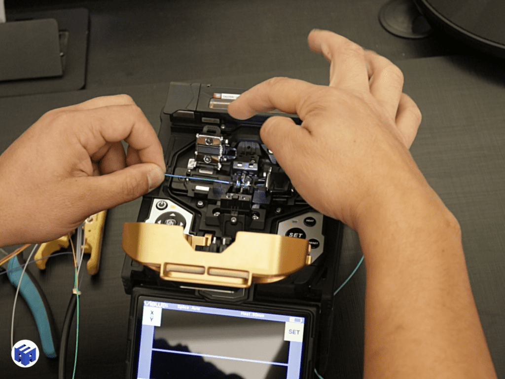
Preparation, cleaning, and cleaving
Many fusion-splicing problems begin before the electric arc. Dust, coating residue, angled cleaves, scratched fiber, or improper positioning can cause an unstable splice or higher-than-expected loss.
Cleaning must use materials suitable for optical fiber and prevent recontamination after preparation. The cleave must produce an end face appropriate for fusion-splicer alignment; a worn or poorly adjusted cleaver increases process variability.
The technician must also preserve the free-fiber length required for routing in the tray. Removing too much coating or working with insufficient slack makes future maintenance more difficult.
Core alignment and cladding alignment
Fusion splicers use different alignment methods. In general, equipment may align fibers based on cladding geometry or use optical systems to locate the core. The appropriate method depends on fiber type, required precision, the equipment, and the work being performed.
A splice should not be evaluated only by the commercial name of the alignment method. Electrode condition, selected program, cleaning, cleaving, environmental conditions, and operator skill continue to influence the result.
The loss shown by the fusion splicer is not the final test
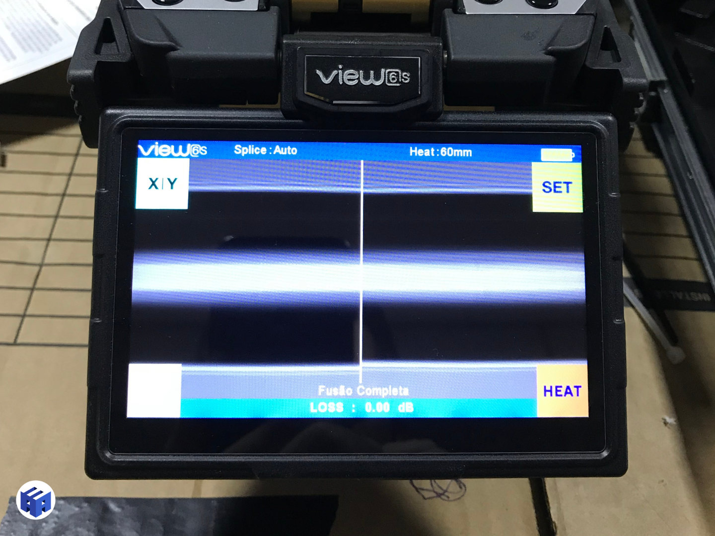
After the arc, the fusion splicer normally displays a loss estimate calculated from images and internal parameters. This number is useful for detecting a visibly inadequate splice and for immediate installation quality control.
However, it does not measure the actual end-to-end attenuation of the link. Acceptance must use appropriate instruments and test methods — such as LSPM/OLTS for end-to-end loss and OTDR for event characterization — according to the project scope and NBR 16869-2.
A “0.00 dB” reading on the fusion splicer does not prove that the complete link is within the optical loss budget.
How much loss can a fusion splice have?
Allowable loss must be treated at two levels: the hardware/standard limit and the design/acceptance criterion. NBR 14565 uses up to 0.30 dB per splice as an optical-hardware reference. This value should not be interpreted as the desirable result for every fusion splice performed.
In a design with multiple splices, simply consuming 0.30 dB at each one can excessively reduce the available margin. Therefore, the optical loss budget should define the total allowable channel loss and may establish stricter installation criteria.
| Element | Design reference | Note |
| Fiber | attenuation per km and wavelength | increases with link length |
| Mated connection | up to 0.75 dB as a hardware reference in NBR 14565 | the design may require better performance |
| Splice | up to 0.30 dB as a hardware reference in NBR 14565 | should not become an automatic installation target |
| Engineering margin | defined by the design | preserves operational tolerance and uncertainty allowance |
Optical loss budget: fusion splicing consumes margin
The loss budget adds the contributions from the cable, connectors, mated connections, splices, and other passive components and compares the total with the limits of the application and transceivers.
When construction adds unplanned splices — for example, because a cable is too short, is damaged, or the route changes — the designer must recalculate the budget. The solution of “adding one more fusion splice” may be technically acceptable, but it must fit within the available margin and be recorded in the as-built documentation.
DIOs, pigtails, and splice trays
In rack installations, optical cables are commonly terminated by fusion-splicing their fibers to pigtails that connect to the DIO adapters. The tray protects the splice protectors and organizes fiber slack.
DIO capacity should consider the number of current fibers, spare capacity, trays, connector type, pigtails, identification, bend radius, and expansion. Crowding splice protectors or coiling fibers without control makes maintenance more difficult and can create macrobends.
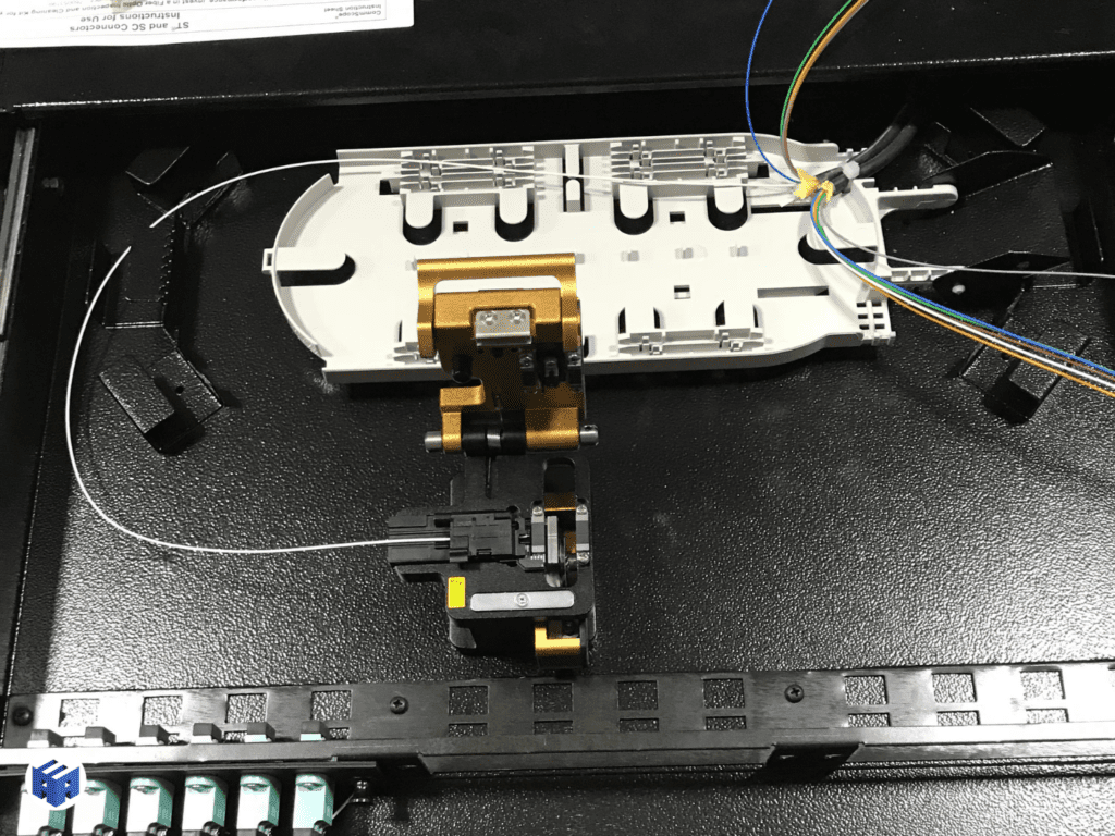
Good documentation associates each optical port with the fiber, tube, cable, origin, destination, and splice tray. This reduces the risk of working on the wrong fiber during maintenance.
Bend radius and fiber routing
Even after a good fusion splice, poor routing can degrade the link. Excessively tight bends, cover pressure, disorganized fiber crossings, or improperly positioned slack can create additional loss.
NBR 16415 requires pathways and organization to respect the minimum radius specified by the manufacturer and, when no specification is available, provides general references for different cable types. Inside the DIO or enclosure, the practical rule is to preserve the geometry intended by the system manufacturer and maintain sufficient slack for future interventions.
Splices in single-mode and multimode fiber
Both single-mode and multimode fibers can be fusion-spliced, but testing and result interpretation must consider the fiber type and applicable wavelengths.
According to NBR 16869-2, multimode cabling measurements use 850 nm and 1,300 nm; single-mode measurements use 1,310 nm and 1,550 nm. Fiber compatibility must also be verified: mixing categories, constructions, or optical characteristics without analysis can produce unexpected behavior.
LSPM/OLTS vs. OTDR after fusion splicing
The estimate displayed by the fusion splicer is not link acceptance. To demonstrate the infrastructure, attenuation must be measured and, when specified, events must be characterized using calibrated equipment, a defined methodology, and traceable reports.
The two methods answer different questions.
| Method | Main question answered | Role in acceptance |
| LSPM / OLTS | What is the total link attenuation? | Compares end-to-end loss with the limit |
| OTDR | Where are the events, splices, connectors, and anomalies? | Characterizes the link and locates events |
| Optical inspection | Is the connector end face clean and undamaged? | Prevents false results and interface damage |
NBR 16869-2 requires inspection and cleaning of the test-system and cabling interfaces. Contamination can alter results and even damage a connection. A dirty connector must be cleaned and reinspected before measurement.
For OTDR testing, a launch fiber and receive cord are used to characterize the initial and final interfaces. Bidirectional testing may be necessary when an appropriate quantitative measurement of events and splices is required, because differences in backscatter between fibers can distort a unidirectional reading.
Marginal results should not be accepted as compliant
NBR 16869-2 establishes that marginal results are not accepted in optical cabling testing. The result must meet the requirement while accounting for measurement uncertainty, or it must be treated as noncompliant.
In practice, this prevents accepting an installation with reasoning such as “it was practically at the limit.” When there is doubt, the cause should be investigated, the link corrected when necessary, and the test repeated.
How to interpret a splice on an OTDR trace
On an OTDR trace, a splice generally appears as a non-reflective event associated with a change in the backscatter level. The apparent value may vary with the test direction and the characteristics of the connected fibers.
Therefore, for work requiring quantitative evaluation of splices, bidirectional measurements and averaging the two directions reduce the influence of the so-called gainer — a situation in which a splice may appear to show gain in one direction because of differences in backscatter, even though there is no actual signal amplification.
The OTDR also helps locate macrobends, breaks, connectors, and unexpected events along the route.
Quality control during installation
Waiting until hundreds of splices are complete before discovering a systematic problem increases rework. The quality plan may include:
- inspection of materials and pigtails;
- verification of the selected fusion program;
- cleaver and electrode checks;
- supervised initial samples;
- periodic review of fusion-splicer loss estimates;
- inspection of trays and fiber slack;
- intermediate testing by segment;
- consolidation of failures by crew or location;
- retesting after corrections.
If several splices from the same work front show high loss, the problem may be cleaning, cleaving, equipment configuration, or material — rather than isolated defects in each fiber.
Optical-cable repairs and restoration
When a cable is broken, the objective is not merely to restore continuity. The repair must consider enclosure location, available slack, the need to insert a new cable section, the additional number of splices, mechanical protection, sealing, and documentation updates.
An improvised restoration may recover service while creating a poor maintenance point or consuming excessive optical budget. For critical networks, the repair plan should define materials, reserves, and contingency strategy before a failure occurs.
Fusion splicing in outdoor enclosures and industrial environments
Fusion splices performed outside technical rooms require attention to moisture, dust, vibration, temperature, sealing, mechanical protection, and maintenance access. The enclosure and cable type must be compatible with the environment.
In industrial plants, substations, and outdoor areas, the design must coordinate fiber with pathways, enclosures, grounding of metallic elements where applicable, mechanical protection, and segregation from other systems. A high-quality splice does not compensate for an enclosure that is unsuitable for the environment.
Procurement: how to technically specify fiber fusion splicing services
The procurement scope should go beyond a “price per splice.” A verifiable specification may include:
| Item | Requirement to define |
| Fibers | type, category, quantity, and identification |
| Fusion splicer | compatible alignment method/capability and proper maintenance |
| Cleaving and cleaning | appropriate tools and consumables |
| Splice protector | type and compatibility with the tray |
| DIO/enclosure | capacity, protection, and organization |
| Loss criterion | design/acceptance limit |
| Testing | LSPM/OLTS, OTDR, and applicable wavelengths |
| Calibration | valid certificates for measurement equipment |
| Documentation | fiber matrix, reports, and as-built documentation |
| Retesting | procedure for failures and corrections |
The contractor should deliver sufficient traceability to relate each result to the fibers actually installed.
Minimum documentation for splices and tests
NBR 16869-2 requires test documentation to report parameters, configuration, equipment, serial number, calibration, wavelengths, fiber category, connectors, reference used, measurement direction, date, operator, and result.
For project governance, it is also advisable to include:
- cable code;
- tube and fiber number;
- origin and destination;
- DIO/enclosure and tray;
- port or adapter;
- splice identification;
- physical route;
- repair history;
- as-built revision.
Commissioning and acceptance of the optical network
Acceptance should combine physical inspection, documentation, and measurement. Receiving OTDR files is not enough without verifying that they correspond to the fibers actually installed.
A robust sequence includes checking DIOs and enclosures, identification, slack, bend radii, cleanliness, polarity, LSPM/OLTS results, OTDR traces when specified, and reconciliation with the as-built documentation. In redundant networks, the team should also verify that the constructed fibers and routes match the designed architecture.
When a splice or link fails, the correction must be recorded and the test repeated. The final product is a proven and traceable optical infrastructure, not merely a set of physically completed splices.
Common mistakes in fusion-splicing services
Recurring problems include:
- accepting the fusion-splicer estimate as certification;
- failing to clean the fiber properly;
- using a cleaver with a worn blade;
- performing splices without prior identification;
- mixing incompatible fibers without analysis;
- routing fiber slack below the appropriate bend radius;
- exceeding tray capacity;
- leaving splice protectors compressed by the cover;
- adding splices without recalculating the loss budget;
- testing only one wavelength when the test plan requires two;
- not using launch fiber/receive cord with the OTDR;
- delivering only PDF files without sufficient native files and traceability;
- accepting marginal results.
Final considerations
Fiber optic fusion splicing is one stage in network construction, but its quality is demonstrated only when design, installation, protection, identification, and testing are treated as a single process.
Splices must be included in the optical loss budget, performed with controlled preparation, protected and organized in appropriate DIOs or enclosures, and verified using consistent test methods. In critical infrastructures, engineering must also ensure that results reconcile with routes, documentation, redundancy, and formal acceptance criteria.
When the optical network is part of an engineering deliverable, test results must reconcile with DIOs, identification, routes, as-built documentation, and formal acceptance criteria. Commissioning turns isolated tests into system-acceptance evidence.
Technical references
[1] ABNT. ABNT NBR 14565:2019 — Cabeamento estruturado para edifícios comerciais. ABNT, 2019. Available at: https://www.abntcatalogo.com.br/.
[2] ABNT. ABNT NBR 16415:2021 — Caminhos e espaços para cabeamento estruturado. ABNT, 2021. Available at: https://www.abntcatalogo.com.br/.
[3] ABNT. ABNT NBR 16869-1:2020 — Cabeamento estruturado — Parte 1: Planejamento e instalação. ABNT, 2020. Available at: https://www.abntcatalogo.com.br/.
[4] ABNT. ABNT NBR 16869-2:2021 — Cabeamento estruturado — Parte 2: Ensaio do cabeamento óptico. ABNT, 2021. Available at: https://www.abntcatalogo.com.br/.
[5] ISO/IEC. ISO/IEC 14763-3 — Implementation and operation of customer premises cabling — Testing of optical fibre cabling. Available at: https://www.iso.org/standards.html.
[6] TIA. ANSI/TIA-568.3-E — Optical Fiber Cabling and Components Standard. Available at: https://tiaonline.org/standards/.
[7] IEC. IEC 61300-3-35 — Fibre optic interconnecting devices and passive components — Visual inspection of fibre optic connectors. Available at: https://webstore.iec.ch/.
Frequently asked questions
It is the permanent joining of two fibers through controlled heating, normally by an electric arc, to form a low-loss optical splice.
NBR 14565 uses 0.30 dB as the maximum hardware reference for a splice, but the design may define stricter installation limits to preserve the optical loss budget.
No. It is an equipment estimate and does not replace link measurement using appropriate methods such as LSPM/OLTS and OTDR according to the test plan.
LSPM/OLTS measures the total end-to-end loss of the link. OTDR characterizes events and helps locate splices, connectors, bends, and anomalies along the fiber.
NBR 16869-2 specifies 850 and 1300 nm for multimode and 1310 and 1550 nm for single-mode in the applicable methods.
It moves the first event beyond the OTDR dead zone and allows the initial link interface to be evaluated properly; a receive cord also allows characterization of the remote end.
It depends on the application. For backbones and permanent links, fusion splicing is generally preferred for stability and low loss; other techniques may be valid when specified by the design.
They are normally protected by heat-shrink splice protectors and routed in splice trays, with controlled slack and bend radii.
NBR 16869-2 does not accept marginal results in optical cabling testing; the result must meet the criterion while accounting for measurement uncertainty.
Complementary technical materials
Related services
- Fiber Optic and Optical Network Design
- Technical Testing and Verification
- Engineering Commissioning
- Telecommunications Design
- Structured Cabling Design
