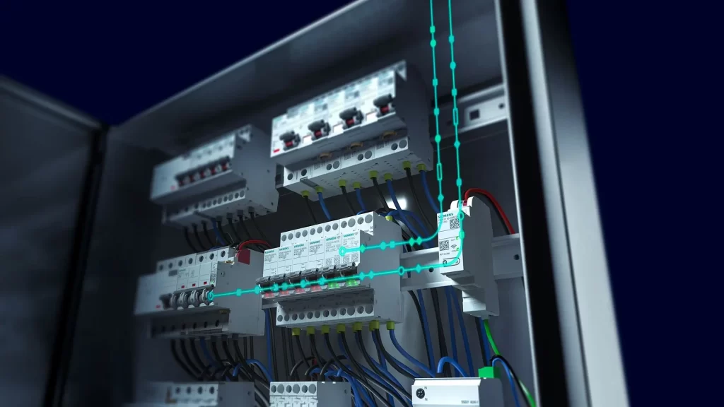
Electrical safety is the set of principles, engineering measures, and operational controls intended to prevent or limit electric shock, arcs, thermal effects and fires, overcurrents, overvoltages, and other hazardous conditions associated with electrical installations and work. It must be built throughout the entire installation life cycle: design, specification, execution, initial verification, operation, maintenance, modifications, and decommissioning. […]
Check it out!
Electrical safety is the set of principles, engineering measures, and operational controls intended to prevent or limit electric shock, arcs, thermal effects and fires, overcurrents, overvoltages, and other hazardous conditions associated with electrical installations and electrical work.
It must be built throughout the entire installation life cycle: design, specification, execution, initial verification, operation, maintenance, modifications, and decommissioning. This involves protection architecture, grounding and equipotential bonding, isolation and protective devices, access and intervention conditions, inspections, tests, documentation, and procedures consistent with the risks.
Electrical safety is therefore a broader concept than training or isolated compliance with NR-10. NR-10 organizes occupational safety and health requirements, while technical standards such as NBR 5410 establish installation criteria. In practice, protection depends on the integration of engineering, actual field conditions, people, documentation, and maintenance.
The objective is to control risk through technical barriers, organization, and verification, preventing a single failure from compromising people, equipment, or operational continuity.
What Is Electrical Safety (and Why Does It Matter)?
Electrical safety is the application, throughout the installation life cycle (design, execution, operation, and maintenance), of principles and measures that keep the risks of electric shock, arc and thermal/fire effects, overcurrents, overvoltages, and electromagnetic disturbances under control.
In practice, this involves preventing access to live parts and ensuring that exposed-conductive-parts do not become hazardous even under fault conditions (basic protection and fault protection), limiting heating and arcs, coordinating devices against overloads and short circuits, treating switching and atmospheric overvoltages through surge-protection measures, providing emergency shutdown, lockout and signaling, and documenting inspections, testing, and maintenance.
Electrical safety is essential to:
- Protect life and property by reducing electric shocks, electrical arcs, and fires;
- Ensure service continuity and operational availability;
- Minimize financial losses from unplanned outages, rework, and equipment damage;
- Improve power quality and electromagnetic compatibility for sensitive loads;
- Enable safe operation and maintenance through isolation, lockout, and continuous verification.
[elementor-template id=”24446″]
Core Principles of Electrical Safety
Electrical safety consists of a set of mutually reinforcing principles and measures that guide the installation from design through maintenance.
Protection Against Electric Shock
Protection against electric shock encompasses the measures intended to limit the current that may pass through the human body and touch voltage to safe values.
This discipline can be divided into basic protection (preventing contact with live parts under normal conditions) and fault protection (ensuring that, if a fault occurs, the supply is automatically disconnected within appropriate times and exposed-conductive-parts do not become hazardous).
In general terms, this involves the use of enclosures and barriers, adequate insulation distances and degrees of protection compatible with the environment, a circuit architecture that reduces the probability and consequences of faults, establishment of a potential reference through grounding and equipotential bonding, and coordination among protective devices for rapid and selective operation.
In practice, risk control combines prevention and limitation of effects.
Material selection and proper conductor routing mitigate damage resulting from faults, while emergency controls, lockout procedures, and signaling enable safe interventions.
Effectiveness depends on systematic verification through visual inspections, continuity and polarity tests, fault-loop impedance measurements, and functional tests of electrical protective devices, along with planned maintenance and operation by qualified personnel to preserve consistent performance throughout the installation service life.
Protection Against Thermal Effects and Fire
Protection against thermal effects encompasses engineering measures intended to prevent ignition and limit fire propagation caused by resistive heating, arcs, and excessive temperature in equipment, conductors, and connections.
It starts with correct sizing of current-carrying capacity using appropriate correction factors, verification of thermal and electrodynamic withstand under short-circuit conditions, and coordination of protective devices to reduce let-through energy and operating times so that heating is controlled before it becomes critical.
At the installation level, this translates into selecting and installing components with thermal characteristics compatible with the environment, routing and segregating circuits to reduce heat accumulation, providing adequate ventilation and heat dissipation for panels and enclosures, controlling temperatures of accessible surfaces, and minimizing contact-resistance points through properly specified and tightened terminals, joints, and connection points.
It also includes the use of materials and arrangements that do not favor flame propagation, sealing penetrations and compartmentalizing spaces to preserve the integrity of critical routes and areas, as well as clear identification of circuits and sources to enable safe and rapid interventions.
Effectiveness depends on systematic verification and maintenance, including visual inspections, functional testing of protections, assessment of operating temperatures, and preventive correction of connections and components subject to thermal aging. The objective is to maintain adequate thermal margins and effective physical barriers throughout the life cycle so that electrical faults do not evolve into fire initiation or compromise people, assets, or operational continuity.
Protection Against Overcurrents
Overcurrent protection concerns the sizing, selection, and coordination of devices capable of limiting and interrupting currents above normal operating conditions — whether due to sustained overload or short circuit — thereby protecting conductors, connections, equipment, and service continuity.
Design begins with defining design currents and circuit current-carrying capacities, proceeds to selecting thermomagnetic or electronic circuit breakers and current-limiting fuses with compatible curves and settings, and verifies that the prospective short-circuit current at the point of installation is below the interrupting capacity of the device and upstream association.
Coordination ensures operation fast enough to respect the thermal and electrodynamic withstand of conductors (let-through energy) without sacrificing selectivity between protection stages, so that only the affected section is disconnected.
In applications with high fault currents or continuity requirements, solutions such as time/energy selectivity and backup (cascading) may be used, in which an upstream current-limiting device reduces stress on the downstream device and increases the associated breaking capacity.
Motor starting, transformer energization, and inrush-current characteristics are considered to avoid nuisance tripping, as are short-circuit contributions from different sources and initial asymmetrical behavior, including peak and DC components.
Verification includes studies of maximum and minimum short-circuit currents, fault-loop impedance, permissible voltage drop, and compatibility among trip curves, documenting single-line diagrams, prospective currents, interrupting capacities, and selectivity tables. During operation, functional inspections, trip-history analysis, retightening, and periodic thermal assessments keep protection aligned with expected performance throughout the installation service life.
Protection Against Lightning
Lightning protection is the set of engineering measures intended to reduce risks arising from direct strikes and the electromagnetic effects of lightning on people, structures, and systems. In the ABNT NBR 5419:2026 series, this protection is structured around general principles, risk assessment, protection against physical damage and life hazards, and protection measures for internal electrical and electronic systems.
It includes interception, conduction, and controlled dissipation of lightning current through external arrangements that intercept the discharge, conduct it along defined paths to the grounding system, and limit potential gradients, avoiding side flashes through adequate separation distances and intentional bonding of metallic parts.
Internally, it integrates surge-protection measures addressing the electromagnetic field generated by lightning within the structure: main and local equipotential bonding, coordinated surge protective devices in stages, cable organization and routing, shielding, and the lightning-protection-zone approach to reduce touch and step voltages and equipment exposure.
The interfaces with power, telecommunications, data, antenna, photovoltaic, and other networks are treated through equipotential bonding and appropriate devices at the point of entry, preserving service continuity and electromagnetic compatibility of the overall installation.
Design begins with an assessment of risk and required performance level, considers structure geometry and materials, external influences, and preferred current paths, and integrates with the grounding system to establish a consistent potential reference.
Effectiveness depends on coordination with internal overvoltage protection, clear technical documentation, and an inspection and maintenance plan that ensures mechanical and electrical integrity of subsystems throughout their service life.
Protection Against Overvoltages and Disturbances
Protection against overvoltages and disturbances includes systematic treatment of temporary overvoltages (TOV) and transient overvoltages — originating from switching operations, network faults, coupling from the lightning electromagnetic field (LEMP), and internal switching — together with management of the electromagnetic compatibility of the installation as a whole.
The objective is to limit the amplitude and energy reaching equipment, maintain stable potential references, and preserve system immunity, reducing nuisance trips, insulation degradation, and latent failures.
The approach integrates surge-protection measures such as main and local equipotential bonding, low-impedance interconnections and defined return paths, coordinated stages of surge protective devices (SPDs) from the service entrance to points close to sensitive loads, and organization by protection zones that divide the environment and grade exposure and immunity levels.
These measures are complemented by cable routing and segregation, minimization of loops and SPD connection lengths, shielding and grounding of screens with proper termination, and isolating interfaces where galvanic coupling introduces risk, such as optical fiber, isolated couplings, and network filters.
Design considers equipment withstand parameters, protective distances and expected surge energy, grounding topology, and the presence of internal disturbance sources such as inductive loads, motor starting, and electronic converters.
Effectiveness depends on coordination among protection stages and switching/overcurrent devices, the quality of equipotential interconnections, and the physical positioning of mitigation elements, together with periodic verification and maintenance — inspection of SPD end-of-life indicators, connection continuity, retightening, measurements, and record updates — to ensure consistent performance throughout service life.
Isolation and Control / Emergency Shutdown
Isolation and control encompass the ability to isolate parts of the installation for safe intervention, switch circuits under load when necessary, and rapidly remove energy under abnormal conditions without introducing new hazards.
Design distinguishes different functions: electrical isolation (disconnection under no-current conditions, with unambiguous open indication and mechanical lockout capability), functional switching (switching under load with compatible breaking capacity), and emergency shutdown (single, immediate, accessible action that reduces risk to people and assets).
Devices intended for isolation should provide visible opening or positive indication of separation, means for locking in the open position, and LOTO provisions; switching devices require adequate interrupting capability, coordination with protections, and resistance to electrodynamic stresses.
The EPO or emergency stop should be clearly identified, unobstructed, close to risk zones, and designed to prevent unexpected re-energization, while preserving essential safety services where applicable, such as emergency lighting, and following a fail-safe logic with intentional reset.
Engineering defines the control architecture, both local and remote, mechanical and electrical interlocks to prevent opening enclosures under load, anti-automatic-reclosing after loss of supply, and clear indication of states and sources.
External influences and enclosure classifications are considered to ensure accessibility and legibility in the field, including aggressive environments and special requirements in classified areas. Interfaces include source switching, zone-based isolation to limit outages, and integration with supervisory systems.
Safe operation requires lockout/tagout procedures, discharge of stored energy, temporary grounding where indicated, and verification of absence of voltage before intervention.
Periodic tests of controls and emergency shutdown, visual inspections, retightening, and functional testing maintain reliability throughout the life cycle, reducing response times and operational risk.
Electrical Protective Devices
A range of devices and equipment is designed to detect abnormal conditions, limit energy or voltage, and interrupt circuits, keeping people, assets, and operations within safe levels.
Selection and specification should consider interrupting capacity and withstand capability, operating curves and selectivity between stages, environmental conditions and external influences, as well as integration with grounding and equipotential bonding.
Main devices include:
- Circuit breakers and fuses — protection against overload and short circuit, with trip/interruption characteristics appropriate to the circuit and available fault current at the point of installation.
- Protection relays and contactors — selective detection of current, voltage, earth faults, and other conditions, together with switching commands and interlocking logic.
- Residual-current devices (RCDs) — mitigation of electric-shock risk under fault/indirect-contact conditions by detecting leakage currents to earth.
- Surge protective devices (SPDs) — limitation of transient overvoltages and integration with internal surge-protection measures.
- Motor protection relays/devices — overload, phase loss, locked rotor, and specific starting/service functions.
- Arc-fault detection devices (AFDDs) — devices intended to detect signatures of series and/or parallel arcing in compatible applications, reducing the probability that arc faults develop into ignition and fire. Application should consider circuit and equipment characteristics and relevant specific standards.
- Arc-flash risk and incident energy — a phenomenon distinct from the function of an AFDD. Occupational assessment considers system configuration, fault current, arcing current, protective-device operating time, working distance, and incident energy. Where applicable, it requires an incident-energy study according to NBR 17227, labeling, mitigation measures, and protection compatible with the risk.
- Disconnectors, lockout switches, and EPO — electrical isolation, lockout/tagout, and accessible emergency shutdown.
- Transformation/isolation and SELV/PELV — reduction of accessible voltages and functional segregation where required.
- Measurement, supervision, and interlocks — continuous monitoring, records, and prevention of unsafe switching operations.
Many commercial products combine functions in a single assembly — for example, circuit breakers with residual-current functionality, fuse-switch disconnectors, SPD modules coupled with circuit breakers, and motor-protection units with integrated thermal/electronic relays. In these cases, analysis should consider aggregate performance and coordination with adjacent stages, together with verification and maintenance requirements needed to preserve system effectiveness.
Installation Points Requiring Attention
The success of an electrical installation depends on disciplined execution and consistent field control, supported by standardized methods, qualified teams, material conformity, interface management, and objective acceptance and commissioning criteria.
When these factors work coherently — with traceability and independent verification — variability and improvisation are reduced, supporting safety, availability, and performance throughout the service life.
Importance of Design
Safety begins in the design. Before any cable or circuit breaker is installed, the design organizes the installation on paper: circuit routes, protection levels, grounding and equipotential bonding, isolation and emergency shutdown, materials, and installation methods.
When this stage is ignored or replaced by field improvisation, the likelihood of electric shock, overheating, recurring trips, equipment failures, and unnecessary outages increases.
Technical Standards
Technical standards establish minimum safety requirements, performance criteria, and verification methods for design, installation, operation, and maintenance.
In Brazil, electrical safety is supported by complementary references. ABNT NBR 5410 establishes requirements for low-voltage electrical installations; ABNT NBR 14039 addresses medium-voltage installations from 1.0 kV to 36.2 kV; and the ABNT NBR 5419:2026 series structures lightning protection, including risk assessment, external and internal SPDA, grounding, equipotential bonding, and protection measures for electrical and electronic systems.
Other references become decisive depending on the problem. The ABNT NBR IEC 61439 series is central to low-voltage switchgear and controlgear assemblies, including main LV switchboards and panels; ABNT NBR 15749 guides measurement of grounding resistance and surface potentials; and ABNT NBR 17227 establishes the Brazilian methodology for incident-energy assessment and protection of workers against the thermal effects of arc flash. NR-10, in turn, organizes occupational safety and health requirements and must be applied consistently with the actual technical condition of the installation.
Technical Responsibility and Qualified Professionals
Safety depends on decisions made by legally qualified professionals with demonstrated competence. Design, execution, and maintenance require formal technical responsibility, together with settings, tests, and records that demonstrate compliance and performance. Interventions without adequate qualification increase accident risk, warranty loss, and contractual liabilities.
Cost Optimization with Engineering Judgment (Cost × Risk)
Cost reduction is legitimate when based on engineering: material standardization, route rationalization, modularity, and maintainability. “Saving” by undersizing conductors, removing protective devices, eliminating equipotential bonding, or using improvised connections increases the probability of failures, fires, and outages. The reference should be life-cycle cost, not merely the lowest initial price.
Guidance for Users and Facility Managers
In residential and public-use environments, signs such as abnormal heating, burning smell, recurring trips, loose receptacles, and intensive use of adapters indicate the need for technical assessment. During storm periods, reducing exposure of sensitive equipment and following basic safety routines is recommended. Periodic reviews and planned interventions by qualified professionals keep risk at an acceptable level and preserve service continuity.
How to Diagnose Electrical Safety in an Existing Installation?
In existing installations, electrical safety cannot be determined solely by the appearance of switchboards, the existence of grounding, or a set of certificates. Diagnosis must compare documentation, physical condition, electrical parameters, protective devices, operating modes, and verification evidence. This principle is particularly important in installations that have undergone expansions, modifications, equipment replacements, or load changes without coordinated design updates.
For new installations, extensions, and modifications, ABNT NBR 5410 establishes a verification logic consisting of visual inspection and tests before commissioning. The documentation submitted for verification should reflect the installation as built. Minimum inspection items include protection against electric shock and thermal effects, wiring systems, selection and settings of protective devices, isolation, identification, connections, external influences, and accessibility. Where applicable, tests include continuity of protective conductors and equipotential bonding, insulation resistance, verification of automatic disconnection, and functional tests.
For an operating facility, the same logic is useful as the basis for an Electrical Installation Inspection: first establish the baseline; then compare drawings, settings, labels, and records with field conditions; finally define measurements and tests capable of confirming or rejecting the hypotheses raised.
| Observed evidence | What must be verified | Possible engineering follow-up |
|---|---|---|
| Recurring trips | Load, cable cross-section, trip curve/settings, short-circuit current, selectivity, and circuit condition | Diagnosis, short-circuit/selectivity study, or design review |
| Heating in panels, terminals, or busbars | Actual load, connections, temperature rise, ventilation, sizing, and assembly integrity | Inspection, thermography where applicable, main LV switchboard/panel review, and corrective plan |
| Single-line diagram differs from field conditions | Topology, sources, protections, loads, feeders, and operating modes | Field survey, Electrical As-Built, and review of dependent studies |
| Grounding without reliable history | Continuity, equipotential bonding, measurement method, electrode condition, and system application | Inspection, grounding measurement and technical report, or upgrade design |
| SPD operated, absent, or uncoordinated | Surge exposure, topology, connection lengths, classes/types, backup protection, and coordination | Review of SPDs, grounding, equipotential bonding, and interface with SPDA |
| Panel without short-circuit or withstand data | Prospective short-circuit current, Icu/Ics of devices, Icw/Ipk/Icc of the assembly, selectivity, and panel documentation | Short-circuit study, main LV switchboard review, and verification according to the 61439 series |
| Energized work with unknown thermal risk | Configuration, fault/arcing current, protection operating time, working distance, and operating scenarios | Incident Energy and Arc-Flash Risk Study |
| Fragmented NR-10 documentation | Scope, design, inspections, measurements, procedures, workers, studies, and traceability | Due diligence, update of the PIE, and upgrade plan |
The value of diagnosis lies in turning symptoms into verifiable hypotheses.
A tripping breaker, an overheating panel, or grounding with a “low value” does not, by itself, explain the safety condition. Engineering must identify cause, consequence, required evidence, and the impact on the installation’s other documents and studies.
Main LV Switchboards and Electrical Panels: Why Do They Concentrate Critical Risks?
Main LV switchboards, distribution boards, and industrial panels concentrate busbars, switching and protective devices, connections, auxiliary circuits, and operating interfaces. Therefore, a safety analysis should not merely verify whether circuit breakers “fit” the panel or whether rated current appears sufficient.
The ABNT NBR IEC 61439 series structures construction and performance requirements for low-voltage assemblies. Relevant topics include protection against electric shock, clearances and creepage distances, integration of devices, internal circuits and connections, temperature rise, short-circuit withstand, electromagnetic compatibility, design verification, and routine verification.
From a safety perspective, three questions are particularly important. First: is the available short-circuit current at the point compatible with device ratings and assembly withstand? Second: do thermal arrangement, connections, and loading keep temperatures within expected conditions? Third: do the protective circuit and barriers remain intact and verifiable during operation and maintenance?
The parameters Icw, Ipk, and Icc are not merely catalog details. They relate to the ability of an assembly to withstand thermal and electrodynamic stresses from short circuits. Likewise, the breaking capacity and settings of circuit breakers must be consistent with the short-circuit, selectivity, and protection-coordination study.
This interface also influences arc-flash risk. ABNT NBR 17227 requires system modeling to use an updated basis and that changes in settings, devices, transformers, topology, cables, motors, or short-circuit level be assessed because they can alter incident energy. Therefore, retrofitting a main LV switchboard or changing protection should not end with the physical replacement of equipment; it may require updates to studies, procedures, labels, and documentation.
When there is uncertainty about the condition of an existing assembly, the technical path may involve inspection, field survey, electrical studies, design review, and, depending on the case, engineering of main LV switchboards and low-voltage panels, with defined verification and acceptance criteria.
From Risk to Scope: When Does Electrical Safety Require Inspection, Study, or Design?
One challenge after identifying an unsafe condition is defining what should actually be contracted. Terms such as “electrical report,” “electrical upgrade,” or “NR-10” may be used generically for technically different problems. A good scope begins with the question that must be answered and the evidence needed to close the uncertainty.
| Need | Most suitable engineering scope | Expected result |
|---|---|---|
| It is unclear whether the existing installation is consistent with design and applicable standards | Technical inspection + document review | Baseline, nonconformities, evidence, and action plan |
| There is no reliable documentation of the as-built condition | Survey + As-Built | Diagrams, drawings, and records consistent with field conditions |
| There is load expansion, new equipment, or architecture change | Capacity study + electrical design | Sizing, protection, distribution criteria, and design documentation |
| There are trips, poor selectivity, or uncertainty about breaking capacity | Short-circuit + selectivity + protection coordination | Fault levels, settings, curves, and protection criteria |
| There is energized work or intervention in panels with relevant thermal risk | Incident-energy study | Incident energy, distances, scenarios, mitigation, and labeling |
| There is uncertainty about grounding/equipotential bonding | Inspection + measurements + design if required | Continuity, interpreted measurements, gaps, and engineering solution |
| There is SPDA without history, building modifications, or SPD failures | SPDA inspection/report + design review when necessary | System compliance, continuity, documentation, and upgrade plan |
| There is an NR-10/PIE compliance requirement in a complex installation | Electrical due diligence + requirements/evidence matrix | Scope, gaps, priorities, and technical upgrade packages |
| The installation is ready for energization or handover | Inspection + testing + commissioning | Verification evidence, punch list, acceptance, and operating baseline |
This framing avoids two extremes: contracting only a descriptive report when design and study gaps exist, or commissioning physical intervention before understanding the cause and technical dependencies. In industrial installations, data centers, critical buildings, and multi-site operations, the sequence diagnosis → prioritization → studies/design → implementation → verification → As-Built generally provides greater traceability and better CAPEX control.
When the objective is to convert a diffuse condition into a technically contractible plan, the Electrical Safety and NR-10 Compliance solution serves as an entry point for integrating inspections, studies, documentation, and design according to the nature of each gap.
Common Errors That Cause Incidents (and How to Avoid Them)
- Absence of RCDs on receptacle circuits and wet areas — apply high-sensitivity RCDs where indicated and test them periodically
- Poorly positioned or uncoordinated SPDs — protect service entrance and panels, minimize connection lengths, and coordinate protection levels
- Undersized conductors and overheating connections — size for current-carrying capacity/voltage drop and execute terminations with correct connectors and torque
- Insufficient breaking capacity — coordinate Icu/Icn with prospective short-circuit current and, when necessary, use backup/cascading solutions
- Lack of selectivity — adjust curves so that only the affected section disconnects, preserving service continuity
- Deficient grounding/equipotential bonding — ensure continuity and bonding among exposed-conductive-parts and services; avoid isolated “grounds” that increase touch voltages
- Enclosures/IP ratings unsuitable for the environment — select IP/IK and materials compatible with conditions, while maintaining ventilation and firestopping
- Improper segregation and routing — separate power, control, and data; reduce loops and critical lengths
- SPDA separation distances ignored — avoid side flashes through adequate equipotential bonding and use of SPDs at interfaces
- Lack of identification and “as built” documentation — identify circuits/devices and keep diagrams and records updated
- Insufficient commissioning — perform inspections, measurements (continuity, loop impedance), and functional tests before energization
- Improvised use conditions — avoid multi-plug adapters/unauthorized branches and provide adequate numbers of outlets and circuit capacity
Conclusion
Electrical safety results from a coherent system: design criteria converted into disciplined installation, coordinated protections, effective grounding and equipotential bonding, initial verification, and periodic maintenance. Treated this way, it reduces shocks, fires, and losses, supports service continuity, and provides greater cost predictability throughout the life cycle. The work of qualified professionals and the adoption of sound practices convert risk into consistent performance — from initial energization through routine operation.
Technical References
[1] BRAZIL. Ministry of Labor and Employment. NR-10 — Segurança em Instalações e Serviços em Eletricidade. Consult the official text on the MTE portal.
[2] ASSOCIAÇÃO BRASILEIRA DE NORMAS TÉCNICAS. ABNT NBR 5410 — Instalações elétricas de baixa tensão. Consult the current edition in the ABNT Catalog.
[3] CONSELHO FEDERAL DE ENGENHARIA E AGRONOMIA. Anotação de Responsabilidade Técnica — ART. Consult the guidance at Confea.
[4] ASSOCIAÇÃO BRASILEIRA DE NORMAS TÉCNICAS. ABNT NBR 5419:2026 series — Protection against lightning. Consult the four current parts in the ABNT Catalog.
[5] ASSOCIAÇÃO BRASILEIRA DE NORMAS TÉCNICAS. ABNT NBR 17227 — Incident energy for protection of workers against arc flash. Consult the current edition in the ABNT Catalog.
[6] ASSOCIAÇÃO BRASILEIRA DE NORMAS TÉCNICAS. ABNT NBR IEC 61439-1 — Low-voltage switchgear and controlgear assemblies — Part 1: General rules. Consult the current edition in the ABNT Catalog.
[7] ASSOCIAÇÃO BRASILEIRA DE NORMAS TÉCNICAS. ABNT NBR 15749 — Measurement of grounding resistance and surface potentials in grounding systems. Consult the current edition in the ABNT Catalog.
[8] ASSOCIAÇÃO BRASILEIRA DE NORMAS TÉCNICAS. ABNT NBR 14039 — Medium-voltage electrical installations from 1.0 kV to 36.2 kV. Consult the current edition in the ABNT Catalog.
Frequently Asked Questions
Electrical safety is the set of engineering measures, procedures, and controls intended to reduce the risks of electric shock, arc flash, fire, overvoltages, failures, and unsafe interventions throughout the installation life cycle.
NR-10 establishes safety requirements for electrical installations and work. Its application should be integrated with design, documentation, the PIE where applicable, procedures, inspections, and risk-control measures.
No. They are important measures, but safety also depends on sizing, overcurrent and surge protection, equipotential bonding, isolation, inspection, maintenance, documentation, and procedures compatible with the risks.
Inspection is particularly important for new installations, modifications, extensions, changes in use, failure events, lack of documentation, PIE updates, and situations in which the actual condition must be verified against design and safety criteria.
Additional Technical Materials
Related Solutions
- Electrical Safety and NR-10 Compliance
- Low-Voltage Electrical Engineering
- Grounding and Equipotential Bonding
Related Engineering Services
- Electrical Installation Inspection
- Electrical Installations Record (PIE)
- Incident Energy and Arc-Flash Risk Study
- Short-Circuit, Selectivity, and Protection-Coordination Study
- Low-Voltage Electrical Design
Related Technical Content
- NR-10
- Electrical Installations Record
- Incident Energy Calculation and NBR 17227
- Protection Against Electric Shock
- NBR 5410
