Understand the main electrical grounding schemes according to NBR 5410, including TN-S, TN-C-S, TN-C, TT, and IT, with their characteristics, applications, and safety requirements.
Check it out!
Grounding scheme is the form of connection between the electrical supply, the exposed conductive parts of the installation, and the earth. This classification defines how the neutral point of the power source and the accessible conductive parts (masses) relate to the grounding system, determining the conditions for protection against electric shock, overvoltages, and insulation faults.
In this article, we present the main types of grounding schemes according to NBR 5410 – including TN-S, TN-C-S, TN-C, TT, and IT – explaining their characteristics, practical applications, and regulatory requirements.
Take a look!
[elementor-template id=”24446″]
What Is an Electrical Grounding Scheme?
Electrical grounding schemes are the standardized way in which connections are established between the power source, the exposed conductive parts of the electrical installation, and earth, with the objective of ensuring people’s safety and equipment protection.
This classification is regulated by ABNT NBR 5410, which determines the technical criteria to be observed in the design and execution of low-voltage installations.
The standard adopts an international symbolism composed of letters indicating the condition of the supply in relation to earth, the situation of the installation’s exposed conductive parts, and the arrangement of the neutral and protective conductors. Correct interpretation of this symbolism is decisive for selecting the appropriate scheme for each type of installation.
Grounding Schemes According to NBR 5410
In the classification of electrical grounding schemes, the following symbolism is used:
- First letter – Supply condition in relation to earth:
- T = one point directly grounded;
- I = insulation of all live parts in relation to earth or grounding of one point through impedance;
- Second letter – Situation of the electrical installation’s exposed conductive parts in relation to earth:
- T = masses directly grounded, regardless of the possible grounding of one supply point;
- N = masses connected to the grounded supply point (in alternating current, the grounded point is usually the neutral point);
- Other letters (when applicable) – Arrangement of the neutral conductor and protective conductor:
- S = neutral and protective functions ensured by separate conductors;
- C = neutral and protective functions combined in a single conductor (PEN conductor).
TN Scheme
The TN scheme has one point of the supply directly grounded, with the exposed conductive parts connected to that point through protective conductors.
In the practice of low-voltage installations in Brazil, this point corresponds, in almost all cases, to the neutral of the distribution transformer. In special scenarios – such as three-phase systems with no neutral available – other supply points may be grounded.
Three variants of the TN scheme are considered, according to the arrangement of the neutral conductor and the protective conductor, namely:
- TN-S scheme
- TN-C-S scheme
- TN-C scheme
TN-S Scheme
The TN-S scheme is the TN system variant in which the neutral conductor (N) and the protective conductor (PE) are completely separated throughout the entire electrical installation.
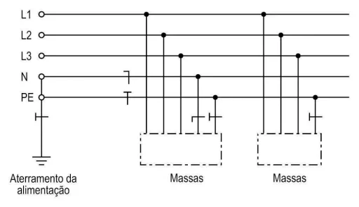
Diagram extracted from NBR 5410:2004
This full separation ensures greater reliability and reduces the possibility of unwanted current circulation in the protective conductor. As a result, the TN-S scheme is widely adopted in low-voltage installations that require a high level of electrical safety, such as commercial, industrial, and hospital buildings.
TN-C-S Scheme
The TN-C-S scheme is the TN system variant in which, in part of the installation, the neutral (N) and protective (PE) functions are combined in a single conductor, called the PEN conductor, and in another part are carried separately.
Technically, this arrangement works as follows:
- From the supply point to a certain point in the installation, the PEN conductor is used, simultaneously carrying both neutral and protective functions.
- From a defined point onward (usually at the main distribution board), a separation occurs into two distinct conductors: the neutral (N) and the protective conductor (PE).
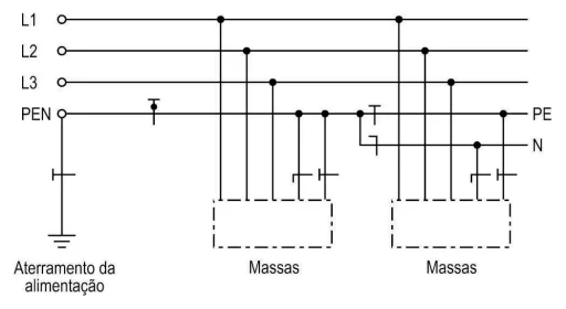
Diagram extracted from NBR 5410:2004
This configuration is very common in public power distribution networks, where the utility supplies the system in TN-C up to the building entrance, leaving it to the designer and installer to perform the separation to TN-S inside the user’s installation.
TN-C Scheme
The TN-C scheme is the TN system variant in which the neutral (N) and protective (PE) functions are permanently combined in a single conductor, called the PEN conductor, throughout the entire installation.
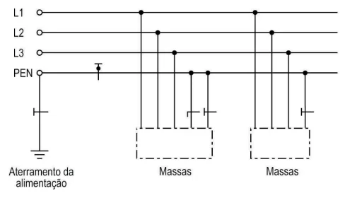
Diagram extracted from NBR 5410:2004
This scheme is still found in older distribution networks and low-complexity installations, but its use is currently limited for safety reasons. The main limitation arises from the risk of interruption or poor contact in the PEN conductor, which can bring metallic masses to phase voltage, significantly increasing the risk of electric shock.
TT Scheme
The TT scheme is characterized by direct grounding of one point of the power source (usually the transformer’s neutral), while the masses of the installation are connected to one or more dedicated grounding electrodes, separate from the grounding electrode used by the source.

Diagram extracted from NBR 5410:2004
In practice:
- The power utility performs neutral grounding in its own system.
- The user must implement an independent grounding system for the installation’s masses, interconnecting metallic equipment housings and conductive structures to local rods or grounding grids.
- Thus, the consumer installation’s electrode is not the same as the one used for the supply neutral.
IT Scheme
In the IT scheme, all live parts are insulated from earth or one point of the supply is grounded through impedance (figure 5). The installation masses are grounded, with the following possibilities:
- masses grounded at the same grounding electrode as the supply, if one exists; and
- masses grounded at their own grounding electrode(s), either because there is no grounding electrode for the supply, or because the grounding electrode for the masses is independent of the grounding electrode for the supply.
Conclusion
Electrical grounding is an indispensable element for the safety of people, the preservation of equipment, and the reliability of the entire electrical installation.
Defining the most appropriate grounding scheme – whether TN-S, TN-C-S, TN-C, TT, or IT – must be based on careful technical analysis, considering the installation characteristics, supply conditions, and safety requirements. This choice cannot be random: it must be supported by a standards-compliant electrical design, prepared by a qualified professional registered with CREA, ensuring compliance and legal certainty for the party responsible for the building.
Correct grounding system design reduces the risk of electric shocks, fires, and damage resulting from lightning events or overvoltages and is therefore a technical and legal requirement in compliance with ABNT NBR 5410 and, when applicable, ABNT NBR 5419.
Final Considerations
At A3A Engenharia de Sistemas, we develop executive electrical installation designs and provide specialized technical consulting in compliance with Brazilian and international standards. Our team evaluates each case with regulatory rigor and practical vision, ensuring that your project has a safe, efficient, and certified grounding system.
Contact us and learn more about our electrical design, consulting, and grounding and lightning protection system deployment services. We deliver high-performance engineering solutions designed to protect people, equipment, and assets.
Normative References
BRAZILIAN ASSOCIATION OF TECHNICAL STANDARDS. ABNT NBR 5410: Low-voltage electrical installations. Rio de Janeiro, 2004.
BRAZILIAN ASSOCIATION OF TECHNICAL STANDARDS. ABNT NBR 5419: Protection against lightning. Rio de Janeiro, 2015.
BRAZILIAN ASSOCIATION OF TECHNICAL STANDARDS. ABNT NBR 15751: Grounding systems for substations. Rio de Janeiro, 2009.
INTERNATIONAL ELECTROTECHNICAL COMMISSION. IEC 60364-4-41: Low-voltage electrical installations – Part 4-41: Protection for safety – Protection against electric shock. Geneva, 2017.
INTERNATIONAL ELECTROTECHNICAL COMMISSION. IEC 60364-5-54: Low-voltage electrical installations – Part 5-54: Selection and erection of electrical equipment – Earthing arrangements and protective conductors. Geneva, 2011.
INSTITUTE OF ELECTRICAL AND ELECTRONICS ENGINEERS. IEEE Std 80: Guide for safety in AC substation grounding. New York, 2013.
INSTITUTE OF ELECTRICAL AND ELECTRONICS ENGINEERS. IEEE Std 142: Recommended practice for grounding of industrial and commercial power systems (Green Book). New York, 2007.
NATIONAL FIRE PROTECTION ASSOCIATION. NFPA 70: National Electrical Code. Quincy, 2023.
Frequently Asked Questions
In the TN-S scheme, the neutral (N) and the protective conductor (PE) are separated from the origin of the installation, ensuring greater safety and better performance of protective devices.
In the TN-C scheme, the neutral and the protective conductor are combined in a single conductor (PEN) throughout the circuit, which reduces costs but increases electrical risks and imposes regulatory restrictions.
The TN scheme is a grounding system in which the source neutral is directly grounded and the exposed conductive parts of the equipment are connected to that point through protective conductors.
It has variants (TN-S, TN-C, and TN-C-S) and is widely used in installations where fast automatic disconnection in case of fault is desired.
NBR 5410 establishes that every electrical installation must have an adequate grounding system, defined in the design, with the objective of protecting people, animals, and property against electric shock and faults.
The standard defines the TN, TT, and IT schemes, as well as the criteria for protective conductors, equipotential bonding, and operation of protective devices.
The main types of grounding systems are:
TN (TN-S, TN-C, and TN-C-S),
TT,
IT.
Each scheme has its own characteristics and must be chosen according to the type of supply, level of risk, service continuity, and regulatory requirements.
In the TN-S scheme, the protective conductor (PE) is interconnected with the source neutral, with physical separation between N and PE from the origin onward.
In the TT scheme, the masses are grounded by the installation’s own electrode, independent of the utility neutral grounding, and the use of RCD devices is mandatory.
The main difference is that in the TN-S scheme the neutral and the protective conductor are separate, whereas in the TN-C scheme they are combined in a single PEN conductor.
TN-S offers a higher level of electrical safety, while TN-C has application restrictions and is not recommended for modern installations or those using RCD devices.
Relevant Links (Complementary Technical Materials)
Grounding and Equipotential Bonding: Design and Best Practices in Electrotechnical Systems
NBR 5410: Low-Voltage Electrical Installations
NR 10 – Complete Guide to Safety in Electrical Installations
Understand What Electrical Safety Is and Why It Matters
Lightning Protection Systems (LPS)
Electromagnetic Compatibility in Critical Environments: Design Challenges and Technical Solutions