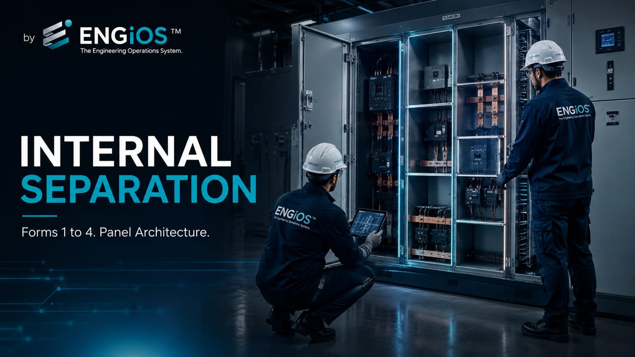
Understand the forms of internal separation in main low-voltage switchboards, the differences between Forms 1, 2, 3 and 4, and how to select the appropriate compartmentation.
Check it out!
Forms of internal separation in a main low-voltage switchboard classify how busbars, functional units, terminals and external conductors are segregated within the assembly. The direct answer is: Form 1 has no internal separation; Form 2 separates busbars from functional units; Form 3 also separates functional units from one another; and Form 4 adds segregation of the terminals associated with each unit.
The form does not represent an automatic quality scale. It is a functional characteristic of the assembly and should be selected according to operational continuity, maintenance, access, risk, dimensions, ventilation, cable entries and isolation strategy.
The choice should not be based only on the idea that “the higher the form, the better.” Each level has implications for cost, dimensions, accessibility, maintenance and operational continuity.
What is internal separation in a main low-voltage switchboard?
Internal separation is achieved by barriers, partitions, compartments or by the construction of the components themselves. Its purpose is to create segregation between internal parts of the assembly.
It can contribute to:
- reducing accidental contact with hazardous parts;
- limiting access to energized busbars;
- separating functional units;
- organizing terminals and conductors;
- facilitating inspection and maintenance;
- reducing fault propagation between compartments;
- allowing intervention in part of the assembly while other parts remain in service, when the design permits.
Internal separation does not eliminate the need for safety procedures, isolation and risk assessment. NBR 5410 requires devices and assemblies to be selected according to service conditions, external influences, accessibility and the need for isolation. The NBR IEC 61439 series treats the form of separation as a design characteristic of the assembly linked to operation and maintenance.
The form of separation must be linked to the operational need
The technical white paper on main low-voltage switchboards shows how to define form, accessibility, functional-unit type, expansion and acceptance criteria without treating compartmentation as an isolated requirement.
Which elements are considered in the classification?
The classification considers the relationship between four main groups:
1. main and distribution busbars; 2. functional units, such as circuit breakers and starters; 3. terminals for external conductors; 4. external conductors associated with the functional units.
The forms represent progressive levels of segregation between these elements.
Form 1: no internal separation
In Form 1, there is no internal separation between busbars, functional units and terminals.
It is the simplest and most compact solution. It may be suitable when:
- the assembly has low complexity;
- maintenance is performed with the panel completely de-energized;
- partial continuity is not required;
- dimensions and cost need to be reduced;
- access is restricted to qualified persons.
The main limitation is that opening the assembly may expose different internal parts simultaneously.
Form 2: busbars separated from functional units
In Form 2, busbars are separated from functional units. Terminals may remain near the busbars or be separated, depending on the adopted configuration.
Form 2a
The busbars are separated from the functional units, but the external-conductor terminals are not separated from the busbars.
Form 2b
The busbars are separated from the functional units and the external terminals are also segregated from the busbars.
Form 2 may be used when the objective is to reduce access to the main busbars without requiring complete individual compartmentation of the functional units.
Form 3: functional units separated from one another
In Form 3, busbars are separated from the functional units and the functional units are segregated from one another.
This configuration improves organization and can limit interference from one unit on the others during inspection or maintenance.
Form 3a
The functional units are separated from one another and from the busbars, but the external terminals are not segregated from the busbars.
Form 3b
In addition to separation between busbars and functional units, the external terminals are separated from the busbars.
Form 3 may be suitable for installations that require greater operational continuity and better isolation between circuits, without reaching the terminal segregation level associated with Form 4.
Form 4: segregation of units and terminals
In Form 4, there is separation between busbars, functional units and the terminals associated with each unit.
This is the form with the highest degree of compartmentation among the usual classifications.
Form 4a
The external terminals remain in the same compartment as the associated functional unit.
Form 4b
The external terminals are located in compartments or spaces separate from the corresponding functional unit.
Form 4 can facilitate selective interventions and reduce exposure to parts of other circuits. However, it increases dimensions, construction complexity and cost.
Comparison between forms of separation
| Form | Busbars separated | Units separated from one another | Terminals segregated |
| Form 1 | no | no | no |
| Form 2 | yes | no | partially, depending on 2a or 2b |
| Form 3 | yes | yes | segregation from busbars according to 3a or 3b |
| Form 4 | yes | yes | segregation by functional unit according to 4a or 4b |
The table summarizes the general logic. Construction details must be defined in the assembly drawings and documentation.
The declared form should be analyzed together with the applicable degree of protection during operation, inspection and maintenance. Removing a cover, barrier or unit may reduce the existing protection; therefore drawings, instructions and procedures must indicate which parts remain energized and which accesses are permitted under each condition.
Compartmentation also affects ventilation, thermal dissipation, cable space, bending radii, access to terminals and electromagnetic compatibility. A higher form may require greater internal volume or thermal derating if air circulation is reduced.
Does the form of separation increase safety?
Internal separation can reduce exposure to energized parts and organize interventions more effectively. However, the declared form alone does not guarantee safety for energized work.
The following should also be considered:
- degree of protection during operation and maintenance;
- interlocks;
- isolation devices;
- accessibility of components;
- circuit identification;
- lockout procedures;
- personnel qualification;
- arc-flash risk;
- assembler instructions.
Compartmentation should be part of a broader safety and maintenance strategy. It does not replace protection against electric shock, PE continuity, circuit-breaker coordination, short-circuit studies, arc-flash analysis or lockout procedures.
Internal separation does not replace protection and grounding
The white paper on circuit-breaker sizing explores coordination, selectivity and short circuit. The eBook Electrical Grounding details the PE circuit and equipotential bonding of the assembly.
How do you choose the appropriate form of separation?
The choice should consider the purpose of the main low-voltage switchboard and the actual operating conditions.
Operational continuity
If the installation needs to keep part of the circuits in service during maintenance, greater segregation between functional units may be required.
Maintenance frequency
Assemblies with frequent adjustments, measurements or replacements may require better accessibility and separation.
Operator competence
The design should consider whether the assembly will be operated only by qualified persons or whether certain devices will be accessible to ordinary or instructed persons.
Load criticality
Hospitals, data centers, industrial processes and critical infrastructure may require greater continuity and limitation of fault impacts.
Available space
Higher forms normally require greater internal volume and may increase the dimensions of the assembly.
Total cost
The analysis should consider not only initial cost but also the impacts on maintenance, downtime, expansion and safety throughout the service life.
Form of separation and fixed, removable or withdrawable units
The form of separation and the connection type of functional units are related but different decisions.
A unit may be:
- fixed;
- removable;
- withdrawable.
The ability to remove or withdraw a unit depends on the assembly construction, connections and interlocks. The form classification should not be used as a substitute for defining the functional-unit type.
Form of separation and energized maintenance
The existence of compartments does not automatically authorize maintenance with the assembly energized.
When operation requires inspection or maintenance while adjacent parts remain in service, the user must specify this need. The assembler must provide compatible barriers, clearances, interlocks, access and instructions.
The assessment must also consider legal requirements, safety procedures and the installation risk analysis.
How should the form of separation be documented?
The specification and drawings should indicate:
- required form;
- busbar location;
- functional-unit compartments;
- position of external terminals;
- conductor routing;
- applicable degrees of protection during operation and maintenance;
- unit connection type;
- conditions for access and intervention;
- areas reserved for expansion.
At acceptance, the declared classification must be compared with the actual construction of the assembly. Access to terminals, PE continuity, barrier fastening, identification, correspondence with drawings and interlock operation should also be checked.
The declared form must be demonstrated in the supplied assembly
The Low-Voltage Electrical Design defines the functional need. The Electrical Installation Inspection verifies construction, documentation and actual access and maintenance conditions.
Common specification mistakes
Common mistakes include:
- requiring Form 4 without a defined operational need;
- choosing the form only by tradition or internal standard;
- not distinguishing subdivisions a and b;
- confusing form of separation with internal arc protection;
- assuming the form permits energized work;
- ignoring the impact on dimensions and ventilation;
- not showing compartmentation in the drawings;
- not verifying construction during receipt.
Conclusion
The forms of internal separation define how the main elements of the main low-voltage switchboard are segregated. The choice should be based on operational continuity, maintenance, access, criticality and available space.
A higher form can offer benefits, but it does not replace design, safety procedures or assembly verification. The specification must explain which functional need the compartmentation is intended to meet.
Technical references
[1] ABNT IEC/TR 61439-0:2017 — Guidelines for specifying low-voltage switchgear and controlgear assemblies, including forms of internal separation. Current international reference: IEC TR 61439-0:2022.
[2] ABNT NBR IEC 61439-1 — General rules for low-voltage switchgear and controlgear assemblies. See also IEC 61439-1:2020.
[3] ABNT NBR IEC 61439-2 — Power switchgear and controlgear assemblies. See also IEC 61439-2:2020.
Frequently asked questions
It is the configuration with no internal separation between busbars, functional units and terminals.
In Form 2, busbars are separated from functional units. In Form 3, the functional units are also separated from one another.
In Form 4a, terminals are in the same compartment as the functional unit. In Form 4b, they are in a separate compartment.
Not automatically. Energized maintenance depends on design, accessibility, barriers, interlocks, procedures and risk assessment.
No. The choice should consider continuity, maintenance, space, cost and operational need.
Additional technical materials
Related solutions
- Main Low-Voltage Switchboards and Low-Voltage Electrical Panels
- Low-Voltage Electrical Engineering
- Electrical Safety and NR-10 Compliance
Related engineering services
- Low-Voltage Electrical Design
- Electrical Installation Inspection
- Short-Circuit, Selectivity and Protection Coordination Study
- Commissioning and Acceptance of Electrical Installations
Related technical content
- Main Low-Voltage Switchboard: what it is, function and components
- NBR IEC 61439: requirements for main switchboards and panels
- Icw, Ipk and Icc in Main Low-Voltage Switchboards
- Design and Routine Verification in Main Switchboards
- Incident Energy and Arc-Flash Risk
- FAT and SAT: integrated tests and acceptance criteria
