Understand the RBMK-1000 architecture, core, graphite moderator, fuel channels, control rods, cooling, steam generation and engineering vulnerabilities of Chernobyl Reactor 4.
Check it out!
The RBMK-1000 architecture consisted of a large graphite core traversed by thousands of independent vertical channels. These channels carried fuel, cooling water, control rods, instruments, and auxiliary devices. Instead of concentrating the core inside a single pressure vessel, the design distributed functions across an extensive network of tubes, headers, valves, pumps, and steam separators.
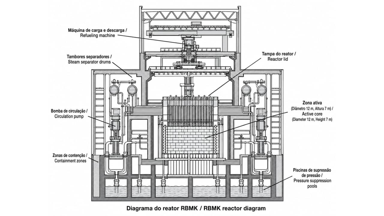
In Chernobyl Reactor 4, the core was approximately 7 meters high and 11.8 meters in diameter. Around 1,660 channels were dedicated to fuel. The structure also included control and instrumentation channels, biological shielding, upper and lower structural plates, a refueling machine, two primary cooling circuits, four steam separators, auxiliary electrical systems, and localized confinement structures.
This article therefore answers the question what the RBMK design looked like inside: a modular, large-scale architecture heavily dependent on the integration of reactor physics, structures, mechanics, hydraulics, instrumentation, automation, power systems, and operations. This arrangement offered industrial advantages, but it also multiplied interfaces and created conflicts among performance, control, and protection.
The previous article explains how the RBMK reactor converted heat into electricity. Here, the focus is different: breaking down the components, systems, and engineering decisions that formed the physical architecture of Reactor 4.
The RBMK Was Not an Ordinary Reactor
RBMK stands for Reaktor Bolshoy Moshchnosti Kanalny, usually translated as “high-power channel-type reactor.” The name already reveals one of the design’s main characteristics: instead of using a single large pressure vessel, the RBMK consisted of many independent vertical channels passing through a large graphite matrix.
According to INSAG-7, Chernobyl Reactor 4 was a heterogeneous pressure-channel reactor with a graphite moderator and boiling light-water coolant. In practical terms, nuclear fission occurred in fuel loaded into individual channels, while the graphite surrounding those channels slowed neutrons and the water removed heat from the core.
The RBMK-1000 had a design thermal power of 3,200 MWt and an electrical capacity of approximately 1,000 MWe gross, or about 925 MWe net per unit. The Chernobyl plant had four operating units, representing approximately 3,700 MWe net installed, plus two additional units under construction at the time of the accident.
This capacity made Chernobyl a strategic facility for the Soviet Ukrainian power system and regional energy security. The claim that the plant supplied 10% of the entire Soviet Union’s electricity demand, however, was not confirmed in the documents reviewed and should be treated with caution.
The RBMK architecture integrated six major groups: core and channels; structures and shielding; cooling; steam and power generation; control and protection; and auxiliary systems. A systems-based analysis shows that overall performance depended less on any isolated piece of equipment than on coordination among disciplines.
This organization increased the number of interfaces among civil, mechanical, electrical, instrumentation, automation, and operations engineering. Each decision needed to be checked not only within its discipline of origin, but also for the effects it produced on the others.
Critical architectures need to be defined before isolated decisions become irreversible.
Front-End Loading structures alternatives, interfaces, risks, availability requirements, and decision criteria before detailed engineering and implementation.
The RBMK Core: Graphite, Fuel Channels and Control Channels
The RBMK core was a very large structure. Reactor 4 had an active zone about 7 meters high and approximately 12 meters in diameter. This region contained the fuel channels, control-rod channels, instrumentation channels, and the graphite-moderator mass.
INSAG-7 records that Reactor 4 had 1,660 fuel channels. These channels were vertical pressure tubes made of zirconium alloy, installed inside vertical ducts in the graphite columns. Each channel contained nuclear fuel and was individually cooled by water.
In addition to the fuel channels, the reactor control and protection system had 211 movable absorber rods in special channels cooled by an independent water circuit. There were also 24 shortened absorber rods, inserted from below, used to control the axial power distribution in the core.
This separation is essential: fuel assemblies occupied the fuel channels; control rods occupied their own channels. Fuel and control did not share the same channel.
Graphite formed the moderator. Its function was to slow the fast neutrons released by nuclear fission, increasing the probability of further fissions in uranium-235. Graphite was neither the fuel nor the main neutron-absorbing material. It was the element that made neutrons more effective at sustaining the chain reaction.
The RBMK-1000 core was approximately 7 meters high and 11.8 meters in diameter. Its scale was significantly larger than that of many other power reactors, making spatial power distribution an important design and operating variable.
The graphite blocks formed the moderating structure and were crossed by vertical channels. Around 1,660 channels received fuel assemblies and pressurized water. Other channels were dedicated to control rods, instruments, detectors, and auxiliary functions. This arrangement created an extensive grid of repetitive components, upper and lower connections, and penetrations through shielding.
The core rested on a lower structural plate and was closed at the top by a heavy plate penetrated by the channel extensions. The side walls provided biological shielding. Integrity of the assembly depended on compatibility among thermal expansion, alignment, welds, supports, sealing, and coolant circulation.
Because the core was so large, distant regions had relatively weak coupling. This required distributed instrumentation and spatial control, as though different zones had to be monitored simultaneously. INSAG-7 emphasizes that a global power indication was not sufficient to represent all relevant internal states.
Large projects require independent review of interfaces, not only of major equipment.
Owner’s Engineering integrates disciplines, verifies requirements, follows design decisions, and reduces gaps among contractors, manufacturers, construction, and operations.
Refueling Machine: Online Refueling
An important operating characteristic of the RBMK was the possibility of refueling while the reactor remained in operation. The refueling machine, positioned above the core, could isolate specific channels and replace fuel assemblies without shutting down the entire unit.
From an availability standpoint, this was a significant advantage. The plant could operate for long periods while replacing fuel locally and maintaining electricity production. From a design standpoint, it reinforced the RBMK’s character as a reactor intended for large-scale continuous generation.
But this same channel architecture also made the core large, spatially complex, and dependent on good power distribution. The RBMK did not behave as a single uniform point. Different regions of the core could have different neutron-flux, steam, temperature, and power conditions.
The Fuel: Uranium, Fuel Rods, and Fuel Assemblies
RBMK fuel consisted of uranium-dioxide pellets enriched to approximately 2% uranium-235 in the original Reactor 4 design. These pellets were encapsulated in zircaloy metal fuel rods.
The physical chain was:
- uranium-dioxide pellets;
- metal fuel rods;
- fuel assembly;
- vertical fuel channel.
According to the technical documentation, each fuel assembly incorporated 18 fuel elements. In the RBMK, two assemblies were positioned in series inside each pressure channel.
Fuel assemblies should not be confused with control rods. Fuel was replaced by the refueling equipment. Control rods were moved by the control and protection system to regulate the nuclear reaction.
Nuclear Fission: Where the Heat Comes From
RBMK energy production began with nuclear fission.
When a neutron strikes a uranium-235 nucleus, the nucleus may absorb the neutron and become unstable. It then splits into smaller fragments, releasing energy, radiation, and additional neutrons.
The simplified sequence is:
- a neutron is absorbed by a uranium-235 nucleus;
- an unstable nucleus is formed;
- the nucleus splits into fission fragments;
- heat, radiation, and new neutrons are released;
- the new neutrons may strike other uranium-235 nuclei;
- the chain reaction continues.
This energy appears mainly as heat in the fuel. The cooling circuit removes that heat, converts it into steam, and enables its conversion first into mechanical energy and then into electrical energy.
The neutrons released in fission are fundamental. Some appear almost immediately; others are produced later through the decay of certain fission products. These delayed neutrons are essential for reactor control because they make the nuclear reaction controllable on a timescale compatible with instrumentation, automation, and human operation.
Where Do the First Neutrons Come From?
During nuclear-reactor startup, neutron sources allow the reaction to be initiated and monitored. There is also a small neutron population generated by natural phenomena such as spontaneous fission and secondary reactions.
After the reactor reaches criticality, nuclear fission itself becomes the main neutron source. The chain reaction sustains itself because each fission releases new neutrons and an appropriate fraction of those neutrons causes additional fissions.
Reactor control consists precisely in maintaining this balance: enough neutrons to sustain the desired power, but not so many as to cause an uncontrolled power increase.
Iodine, Xenon and Reactor Poisoning
During uranium fission, several radioactive products are formed. Among them is iodine-135, which decays into xenon-135.
Xenon-135 is a strong neutron absorber. It is therefore known as a neutron poison. When large amounts of xenon are present in the core, it captures neutrons that could otherwise cause new fissions, reducing reactor reactivity.
The chain is:
- nuclear fission produces fission products;
- iodine-135 is formed among them;
- iodine-135 decays into xenon-135;
- xenon-135 absorbs neutrons;
- neutron absorption reduces reactivity.
At stable power, an equilibrium exists: xenon is produced but is also consumed through neutron absorption. When power falls, neutron flux decreases. Xenon is consumed more slowly, while iodine already formed continues decaying into xenon.
This phenomenon helps explain the Reactor 4 sequence. After power fell to around 30 MWt, xenon made power recovery more difficult. To compensate for this loss of reactivity, operators withdrew many control rods, reducing the operational reactivity margin. This point is analyzed in detail in Chernobyl: Why Did Reactor 4 Power Fall from 500 MWt to 30 MWt?
Water and Graphite: The Combination That Made the RBMK Different
In the RBMK, water and graphite had different functions.
Graphite was the moderator. It slowed neutrons and favored continuation of the chain reaction.
Water was the coolant. It removed heat from the fuel channels. But it also absorbed some neutrons.
This separation between moderator and coolant was decisive. In many reactors, water itself acts simultaneously as coolant and moderator. When water boils and forms steam, moderation decreases, reducing the nuclear reaction. This behavior tends to be stabilizing.
In the RBMK, however, graphite continued moderating neutrons even when the water in the channels turned into steam. Because steam absorbed fewer neutrons than liquid water, steam formation could leave more neutrons available for new fissions.
This is the basis of the positive void coefficient: under certain conditions, more steam could increase reactivity instead of reducing it.
The dangerous sequence was:
- more heat produces more steam;
- more steam reduces neutron absorption by water;
- more neutrons remain available;
- more fissions occur;
- power increases;
- the power increase produces still more heat and steam.
This positive feedback was one of the central factors in Reactor 4’s final instability.
Control Rods: Control, Safety and Design Tradeoff
RBMK control rods contained neutron-absorbing material such as boron carbide. Their function was to regulate the nuclear reaction.
In simple terms:
- rod inserted farther → greater neutron absorption → lower reactivity;
- rod withdrawn farther → less neutron absorption → greater available reactivity.
The control and protection system could operate in automatic, manual, and emergency modes. In an emergency, the shutdown command should insert rods into the core to terminate the sustained chain reaction.
The problem is that the pre-accident RBMK rods had graphite displacers. These displacers did not exist to “brake” the reactor. They were a neutron-efficiency solution: they prevented the channel from being filled with neutron-absorbing water when the absorber rod was withdrawn.
During normal operation, this choice improved neutron utilization. But under certain conditions, especially with many rods withdrawn far from the core, the initial insertion movement could displace water with graphite before the absorber section became fully effective. The initial effect could be a local increase in reactivity.
This characteristic is decisive for understanding why emergency shutdown did not behave as a sufficient barrier during Reactor 4’s final sequence. The topic is discussed in detail in Chernobyl: Why Did the AZ-5 Emergency Button Not Prevent Reactor 4 from Exploding?
Water Enters from Below, Steam Leaves from Above
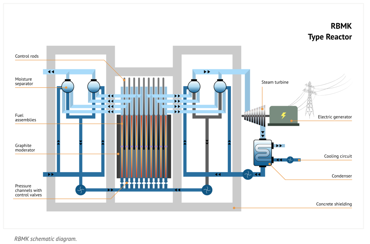
Cooling water entered through the lower part of the fuel channels, passed through the fuel assemblies, and removed the heat produced by nuclear fission.
As it rose through the channels, part of the water boiled, forming a water-steam mixture. This mixture flowed to the steam separator drums.
The separator drums separated steam from liquid water. The steam proceeded to the turbines. The separated water returned to the circulation circuit and flowed back to the reactor.
The RBMK used a direct cycle. This means that steam generated in the reactor’s own circuit was sent directly to the turbines, without an intermediate steam generator as used in pressurized PWR or WWER reactors.
The primary system was divided into two independent circuits, each responsible for approximately half of the core. In each circuit, water passed through main pumps, a common header, and 22 distribution groups before reaching the individual channels.
This distribution required an extensive network of piping and flow-control devices. Each channel needed cooling compatible with its thermal load and core position. After passing through the channels, the water-steam mixture traveled through individual lines to the horizontal separators.
From a design standpoint, the circuit was not merely hydraulic. It depended on electrical power, pressure, temperature, flow, and level instrumentation, protection logic, check valves, isolation, and communication with generation systems. The architecture needed to represent the process state in an integrated manner.
Distributed processes require integrated supervision of variables, states, and alarms.
A SCADA system organizes telemetry, commands, trends, events, and alarms to support operation, diagnosis, and performance analysis in critical facilities.
Circulation Pumps: The Reactor’s Hydraulic Heart
The main circulation pumps maintained water flow through the fuel channels. This forced circulation was indispensable for removing heat from the core.
The circuit was divided into two main loops, each cooling half of the reactor channels. In the accident sequence, the documentation refers to eight main circulation pumps associated with the system.
This point explains why the turbine test was so sensitive. The test objective was to verify whether, during a total loss of power, the inertia of the coasting turbine could maintain enough electrical power to supply essential pumps for long enough until the emergency diesel generators came online.
The test appeared electrical, but it directly affected the ability to maintain water circulation through the core. From an engineering standpoint, it was therefore an integrated critical-system test, not merely an isolated electrical test.
From Heat to Megawatts: The Steam-Turbine-Generator Cycle
After heat was produced in the core, the RBMK followed a direct energy chain:
- nuclear fission produced heat in the fuel;
- water removed that heat in the channels;
- part of the water turned into steam;
- the steam was separated in the separator drums;
- the steam flowed to the turbine;
- the turbine converted thermal energy into mechanical rotation;
- the generator converted mechanical rotation into electrical energy;
- the steam was condensed;
- the water returned to the feedwater circuit.
In the turbine, steam expanded and moved blades connected to a shaft. That shaft drove the electrical generator. The generator produced electricity through electromagnetic induction, which was then sent to the grid through the plant’s electrical systems.
Part of this energy also powered the facility’s own auxiliary systems: pumps, instrumentation, control, ventilation, internal electrical systems, automation, and safety equipment.
Beyond the process components, the RBMK depended on an instrumentation architecture capable of monitoring a very large core. Internal and external detectors, calculation systems, and control-room panels had to combine local and global information to represent power distribution and circuit conditions.
INSAG-7 records that certain important parameters were not presented immediately and in an integrated form. The operational reactivity margin, for example, depended on periodic processing and was not incorporated as a simple protection variable. At low power, internal instrumentation coverage was also reduced.
This problem highlights the difference between having sensors and building situational awareness. The control architecture needs to establish which variables are critical, how they are calculated, where they are displayed, which trends must be compared, and how alarms are prioritized so the operator can understand the system state.
A control system must transform thousands of signals into a coherent operational view.
Digital Supervision and Control Systems integrate data acquisition, logic, events, operator interfaces, and records to increase traceability and situational awareness.
Reactor Cover, Shielding and Containment
The RBMK had biological shielding, reinforced-concrete structures, accident-localization systems, compartments, pressure-suppression pools, and heavy upper structural elements. The reactor cover and upper metal plates were penetrated by the vertical channels.
But an important distinction is required: the RBMK did not have a robust full-containment structure of the type adopted in many Western designs. It had localization and suppression systems, but not a complete containment capable of fully retaining the consequences of severe core destruction.
During the Reactor 4 accident, mechanical destruction of the core and overpressure were sufficient to rupture upper structures, eject radioactive materials, and expose the core to the atmosphere. This helps explain the scale of the subsequent radiological release.
The RBMK’s physical protection consisted of shielding and localized confinement. The core occupied a lined cavity, rested on a lower plate, and was closed by a heavy upper plate. Parts of the primary circuit occupied dedicated compartments connected to pressure-relief and suppression systems.
This solution was not equivalent to a full containment enclosing the entire nuclear facility. Its capability was associated with defined local-failure scenarios. When several channels were affected simultaneously, structural loads could exceed the assumptions considered by the design.
The analysis highlights an engineering principle: barriers need to be verified as a chain. Prevention, detection, control, isolation, relief, and consequence limitation must each have their own criteria and also work in a coordinated manner. One barrier cannot depend on another that has already been compromised by the same event.
Barriers and protections need to be tested against the scenarios that justified their specification.
Commissioning verifies interfaces, sequences, alarms, interlocks, power supply, documentation, and evidence before critical systems are accepted.
What Made the RBMK Efficient
The RBMK offered clear operating advantages within the Soviet logic of large-scale power generation:
- high unit power;
- use of individual fuel channels;
- ability to refuel during operation;
- direct steam cycle;
- high availability for continuous operation;
- design compatible with Soviet industrial capabilities of the period.
These characteristics explain why RBMK reactors were adopted at several plants across the Soviet Union. The design was not irrational from an energy-production standpoint. It responded to specific industrial, energy, and political needs.
The problem is that operating efficiency is not synonymous with safety under limiting conditions. A system may be efficient during normal operation while remaining vulnerable when operated outside its ideal margins.
What Made the RBMK Vulnerable
RBMK vulnerabilities appeared especially in degraded states, at low power, with a low operational reactivity margin, and under abnormal core-power configurations.
Critical points included:
- positive void coefficient;
- large and spatially complex core;
- strong influence of axial and radial power distribution;
- dependence on ORM, the operational reactivity margin;
- control rods with graphite displacers;
- relatively long rod-insertion time before post-accident modifications;
- possibility of operation in dangerous configurations;
- protections and interlocks that could be disabled or bypassed in certain contexts.
The Chernobyl accident cannot be explained by a single characteristic. It resulted from the combination of design, operations, the test, weak safety culture, and insufficient technical governance. This analysis is developed further in Chernobyl: Design Failure, Political Pressure, or Governance Failure?
What Changed After Chernobyl
After the accident, the remaining RBMK reactors underwent important modifications. According to the technical documentation, these changes aimed to reduce the void coefficient, improve emergency-protection effectiveness, display ORM in the control room, and prevent safety systems from being bypassed while the reactor was operating.
Measures included:
- installation of additional fixed absorbers;
- increase in the required ORM;
- increase in fuel enrichment;
- modification of control-rod design;
- reduction in rod-insertion time;
- introduction of a faster emergency-protection system;
- better ORM indication for operators;
- restrictions on unsafe operating modes.
These changes are important because they demonstrate that the vulnerabilities were not merely “later interpretations.” They required concrete engineering corrections.
The Engineering Lesson of the RBMK Design
The RBMK was a powerful, productive design consistent with specific industrial objectives. But its architecture also shows how efficiency-oriented decisions can create risks when they are not assessed under limiting conditions.
Graphite as moderator, boiling water as coolant, the direct steam cycle, individual channels, graphite displacers in the rods, and dependence on ORM formed a complex system. In normal operation, this system could produce energy on a large scale. Under degraded conditions, it could lose safety margins rapidly.
The lesson for consulting engineering is direct: it is not enough to assess whether a system works under the ideal scenario. It is necessary to understand how it behaves during transitions, low-margin conditions, partial failures, degraded operation, testing, maintenance, protection bypasses, and decisions made under pressure.
This is the role of practices such as Owner’s Engineering, commissioning, technical auditing, FEL, and technical due diligence: anticipate risks, validate interfaces, test critical functions, document requirements, and protect the owner against weak technical decisions.
Conclusion: The RBMK Was Efficient, but Not Very Error-Tolerant Under Certain Conditions
The Chernobyl RBMK converted nuclear fission into electrical energy through an apparently direct chain: uranium generated heat, water removed that heat and turned into steam, steam drove turbines, turbines drove generators, and electricity was sent to the grid.
But behind that chain was a complex engineering architecture: a graphite core, individual fuel channels, boiling water, control rods with displacers, high sensitivity to power distribution, xenon effects, and dependence on the operational reactivity margin.
The Reactor 4 accident did not happen because nuclear energy is inherently uncontrollable. It happened because a critical system was brought into a configuration in which design, operating, and governance vulnerabilities aligned.
In the next article in the series, this technical foundation can be turned into a direct explanation of the accident sequence: Chernobyl — the steps that led to the explosion of Reactor 4.
Technical References
[1] INTERNATIONAL ATOMIC ENERGY AGENCY. The Chernobyl Accident: Updating of INSAG-1. Safety Series No. 75-INSAG-7. Vienna: IAEA, 1992.
[2] SHTEYNBERG, N. A. Report by a Commission to the USSR State Committee for the Supervision of Safety in Industry and Nuclear Power. In: INSAG-7, Annex I. Moscow, 1991.
[3] ABAGYAN, A. A. et al. Causes and Circumstances of the Accident at Unit 4 and Measures to Improve the Safety of Plants with RBMK Reactors. In: INSAG-7, Annex II. Moscow, 1991.
[4] UNITED STATES NUCLEAR REGULATORY COMMISSION. Report on the Accident at the Chernobyl Nuclear Power Station. NUREG-1250. Washington, 1987.
[5] MUELLNER, Nikolaus. Three Decades after Chernobyl: Technical or Human Causes? In: The Technological and Economic Future of Nuclear Power. Springer, 2019.
[6] WORLD NUCLEAR ASSOCIATION. RBMK Reactors – Appendix to Nuclear Power Reactors. Updated in 2026.
Frequently Asked Questions
The reactor combined a large graphite stack, individual fuel channels, circulation circuits, steam separators, control, protection, shielding, and auxiliary structures.
They were vertical tubes crossing the core and housing fuel, coolant, control rods, sensors, or other components depending on each channel’s function.
The graphite formed the core moderator, slowing neutrons and creating the neutron environment around the fuel channels.
Main pumps drove water through the fuel channels. The water-steam mixture flowed to separators, steam fed the turbines, and water returned to the circuit.
They separated the steam sent to the turbines from the water that had to return to the reactor circulation circuit.
Rods, drives, sensors, automatic logic, and computer systems worked together to measure the state of the core and control its reactivity.
No. The RBMK channel architecture and building did not correspond to the high-pressure full containment typical of many PWR reactors.
Because changes in electrical supply, pumps, flow, steam, instrumentation, or control could simultaneously alter heat removal, reactivity, and safety margins.
Additional Technical Materials
Solutions
- SCADA Systems
- Digital Supervision and Control Systems
- Requirements, Evidence, and Acceptance-Criteria Management
Engineering Services
Chernobyl Learning Journey
