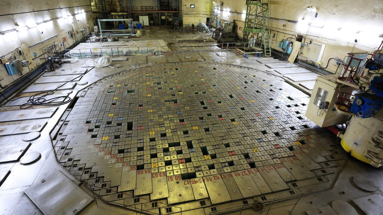
Understand how the Chernobyl RBMK reactor converted heat into electricity through channels, water, steam, turbines, control, and auxiliary systems.
Check it out!
The Chernobyl RBMK reactor was a large power-generation facility that converted heat into steam, mechanical motion, and electrical energy. Its operation depended on integration among the core, water circulation, steam separators, turbines, generators, auxiliary systems, and operational supervision.
Graphite performed the moderation function, while water removed heat and also influenced core behavior. Power was regulated by control rods, automatic systems, coolant flow, feedwater, turbine load, and continuous monitoring of nuclear, thermal, hydraulic, and electrical variables.
Each RBMK-1000 unit had a thermal power of about 3,200 MWt and produced approximately 1,000 MWe. Reactor 4 supplied two turbine-generator sets. The RBMK therefore was not merely a reactor: it was an integrated chain that began in the fuel and ended at the electrical grid.
This article follows that functional chain. The objective is to explain how the RBMK was intended to operate, which systems kept the process stable, and why its operation depended on integration among process, automation, power, telecommunications, and people. The detailed physical breakdown is covered in RBMK Architecture: Components, Circuits, and Systems of Reactor 4.
How Does a Nuclear Power Plant Convert Heat into Electricity?
A nuclear power plant is a thermal power plant. The heat source is in the core, but electricity is produced through a chain similar to that of other thermal plants: heat, steam, turbine, and generator.
- fuel releases heat in the core;
- water removes this heat as it flows through the channels;
- part of the water turns into steam;
- the separators remove steam from the mixture;
- the steam drives the turbines;
- the turbines drive the generators;
- the steam is condensed and returns to the circuit;
- electricity supplies the plant itself and is delivered to the grid.
Energy was not converted directly into electricity. It passed through a sequence of transformations: nuclear energy into heat, heat into steam energy, steam into mechanical motion, and motion into electrical energy.
Performance depended on the balance among all stages. Increasing heat generation without increasing heat removal created an imbalance; changing flow, pressure, or steam extraction also altered the process state.
This chain connects the RBMK to other generation projects. Different technologies still depend on auxiliary systems, protection, transformation, grid connection, telecommunications, supervision, and teams capable of operating the installation.
Critical energy must be treated as an architecture, not as isolated equipment.
Generation, auxiliary services, emergency supply, protection, autonomy, and recovery must be sized together to keep essential functions available.
What Is Nuclear Fission?
Nuclear fission is the splitting of a heavy atomic nucleus into smaller nuclei. In power reactors, the most important element for this process is uranium-235, a uranium isotope capable of sustaining a chain reaction.
When a neutron strikes the nucleus of a uranium-235 atom, the nucleus may become unstable and split. When it does, it releases:
- energy in the form of heat;
- fission products;
- radiation;
- new neutrons.
These new neutrons can strike other uranium-235 nuclei, producing additional fissions. This is how a chain reaction is formed.
The purpose of a nuclear reactor is not merely to initiate this reaction. It is to keep it controlled. If the reaction decreases too much, power falls. If it grows too much, the system must absorb neutrons, reduce reactivity, or restore safe operating conditions.
In other words, a nuclear reactor is an installation designed to control the neutron population in the core. Reactor power depends directly on this balance.
Where Do the First Neutrons Come From?
A common question is: if fission depends on neutrons, where do the first neutrons that start the reaction come from?
The answer involves several natural and operational sources. Even before a reactor is at power, small numbers of neutrons are produced by natural physical processes, such as rare spontaneous fissions in certain heavy nuclei and reactions associated with the nuclear material itself. During startup and controlled operation, neutron sources may also be used to ensure adequate measurement and predictable response in reactor instrumentation.
These initial neutrons are not what makes the reactor powerful. They merely allow the reaction to begin being detected and controlled. What sustains the process is the chain reaction: each fission releases new neutrons, which can cause new fissions, increasing or maintaining power according to the core balance.
Therefore, the central question in a reactor is not only “how does the reaction begin?” but “how is it controlled after it begins?” The answer involves fuel, moderator, coolant, control rods, core geometry, temperature, flow, pressure, protection systems, and operation.
Natural Uranium, Enrichment, and Nuclear Fuel
Uranium found in nature is not composed of only one type of atom. It consists mainly of uranium-238 and a small fraction of uranium-235. Uranium-235 is the most important isotope for fission in thermal reactors because it can sustain a chain reaction more efficiently.
The problem is that the proportion of uranium-235 in natural uranium is low. For this reason, many reactors use low-enriched uranium, meaning uranium processed to increase the fraction of uranium-235 to a level suitable for use as civil nuclear fuel.
In general, the fuel cycle includes stages such as:
- mining uranium ore;
- processing and producing uranium concentrate;
- chemical conversion to a form suitable for enrichment;
- enrichment, which increases the proportion of uranium-235;
- fuel fabrication, usually as ceramic uranium-dioxide pellets;
- assembling these pellets into fuel elements or channels, depending on reactor type.
Enrichment does not mean making uranium “more explosive” in the ordinary sense of the word. In civil nuclear power plants, it means adjusting the isotopic composition of the fuel so that the chain reaction can be sustained and controlled within the reactor design.
In the RBMK, fuel was part of a larger architecture involving individual channels, graphite, cooling water, steam, control rods, and operating systems. Fuel alone does not explain reactor behavior. That behavior emerges from the interaction among all these elements.
What Does RBMK-1000 Mean?
RBMK is the transliteration of the Russian expression for “high-power channel-type reactor.” The number 1000 identifies the unit’s electrical-power class.
Instead of concentrating the entire core inside a single pressure vessel, the design distributed fuel and water through many vertical channels passing through a large graphite structure. This approach made it possible to build high-power units using industrial capabilities available in the Soviet Union.
The architecture also allowed refueling during operation. In return, it created an extensive installation with a large number of channels, pipes, valves, sensors, and operational interfaces.
Overall behavior resulted from the combination of thousands of local conditions. An apparently stable average power level, by itself, did not describe how every region of the core was behaving.
How Was the Fuel Organized?
The fuel was assembled into elements installed inside the vertical channels. Released energy heated the cladding and was transferred to the water flowing around it.
Producing heat was not the only challenge. The system had to distribute power in a controllable manner, continuously remove heat, avoid excessively loaded regions, and preserve suitable conditions for control and protection systems to act.
The channel-based distribution allowed local flow adjustment and monitoring of different regions. At the same time, each channel introduced its own connections, instruments, valves, and limits. The core functioned as a network of interdependent elements, not as a single thermal point.
What Was the Function of Graphite?
Graphite acted as the moderator. Its function was to reduce neutron energy and help maintain the conditions required for a controlled reaction.
Large graphite blocks formed the structure around the channels. A gas mixture circulated among the blocks to assist heat transfer and limit oxidation.
Graphite remained in the core regardless of the amount of water present in the channels. This separation between moderator and coolant distinguished the RBMK from reactor designs in which the same water performs both functions.
What Was the Function of Water?
Water removed the heat produced in the fuel and carried that energy to the separators. As it passed through the channels, part of the water turned into steam.
Water also influenced core behavior. Changes in density and steam fraction altered neutron absorption. This interaction is examined in greater depth in the chapter on the positive void coefficient.
During normal operation, the process had to maintain consistency among power, flow, pressure, inlet temperature, steam fraction, and energy extraction by the turbines.
How Did the Pressure Channels Work?
The core was crossed by vertical channels with an active region of approximately seven meters. Each channel received fuel assemblies and allowed coolant to pass through.
Water entered from the bottom, absorbed heat, and began forming steam as it rose. At the outlet, a water-steam mixture was carried through individual pipes to the separators.
Flow had to be matched to local power. Channels under different conditions required compatible heat removal. Therefore, power, flow, pressure, and steam formation could not be assessed in isolation.
How Was Refueling Performed During Operation?
A dedicated machine could connect to a channel and replace fuel assemblies without shutting down the entire unit. This capability increased availability and allowed gradual management of fuel utilization.
This advantage required configuration control, channel identification, fuel-history tracking, intervention records, and up-to-date documentation. Operational availability and technical governance were inseparable.
How Did Water Circulate Through the RBMK?
The RBMK-1000 had two main cooling circuits, each serving approximately half of the core. Main circulation pumps moved water through distribution headers and the channels.
During normal operation, pumps maintained circulation and reserve capacity was available to replace unavailable equipment. Water left the pumps, passed through headers, and was distributed to individual channels.
After removing heat, the mixture returned to the separators. Water not converted to steam was mixed with feedwater from the condensers and returned to the pump suction.
Flow, inlet temperature, pressure, separator level, and steam production had to remain consistent with power. During startups and load reductions, pump and valve configurations were adjusted to preserve thermal and hydraulic margins.
What Was Inlet-Water Subcooling?
Subcooling is the margin between the actual water temperature and the boiling temperature corresponding to system pressure. With an adequate margin, water began forming steam only after traveling through part of the channel.
This condition influenced thermal stability, pump behavior, and steam distribution. Water too close to boiling reduced the operating margin and could make the process more sensitive to flow changes.
How Did the Steam Separators Work?
Each circuit had large horizontal separators. The mixture from the channels entered these vessels, where steam was separated from water.
Steam went to the turbines; water remained in the recirculation circuit. Level, pressure, feedwater flow, and steam production had to be controlled together.
A change in turbine load altered steam consumption and affected the reactor process. The nuclear circuit and the turbine-generator set were not independent systems.
The RBMK used a direct cycle: steam produced in the channels supplied the turbines without an intermediate steam generator.
How Did Turbines and Generators Produce Electricity?
The separated steam was distributed to two turbines associated with the unit. As the steam expanded, it drove rotors coupled to electrical generators.
After passing through the turbines, the steam was cooled in condensers and returned to the liquid state. Pumps sent the water back into the process.
Part of the electricity supplied the plant’s own loads: pumps, ventilation, instrumentation, valves, lighting, control, and auxiliary systems. The remainder went to transformers and the grid.
What Is the Difference Between MWt and MWe?
MWt represents thermal power produced in the core. MWe represents electrical power delivered by the generators. The RBMK-1000 produced about 3,200 MWt to generate approximately 1,000 MWe.
The difference reflects thermodynamic limitations and cycle losses. Part of the heat had to be rejected through the cooling system.
Process, power, and automation need to share the same operational picture.
SCADA systems transform distributed measurements into screens, trends, alarms, and events that make it possible to monitor installation status and operating margins.
How Was RBMK Power Controlled?
Control combined neutron-absorbing rods, automatic regulators, distributed instrumentation, and operator monitoring. The objective was to keep heat production consistent with water circulation, steam generation, and turbine load.
Because the core was very large, observing a single total value was not enough. Spatial distribution also had to remain within the conditions covered by analysis.
What Was the Operational Reactivity Margin?
The operational reactivity margin, or ORM, was an indicator related to rod configuration and the core’s controllability. Its importance was greater than the way it was presented in the control room suggested.
The subject is explored in ORM in the RBMK: Why a Low Margin Was Dangerous.
Why Did the Rods Have Graphite Displacers?
The displacers were part of the rod design and influenced system behavior under certain configurations. The article Why RBMK Control Rods Had Graphite examines this feature in depth.
What Did Instrumentation and the Control Room Need to Show?
The control room brought together information on power, rod positions, pressure, temperature, flow, levels, pump status, turbine condition, electrical supply, and protection systems.
An apparently stable total power did not guarantee that every region of the core was behaving in the same way. At low power, some measurement and display limitations made interpretation even more difficult.
The process computer assisted calculations and records, but not every important variable was presented with sufficient update rate, priority, and clarity. Having many signals does not mean having situational awareness.
Alarms and events need to be understood in the context of the process.
Digital supervision systems, time synchronization, and sequence-of-events recording help organize trends, events, and operating states into a coherent picture.
What Was Normal RBMK Operation Like?
Under stable conditions, heat generation, water circulation, steam production, turbine consumption, and feedwater remained balanced. Regulators adjusted the process while operators monitored margins, trends, and spatial distribution.
Pumps maintained circulation; separators stabilized steam delivery; condensers returned water to the cycle; and electrical systems supplied the loads needed for generation itself.
The unit also depended on maintenance, calibration, water chemistry, radiation protection, configuration control, periodic testing, and communication between shifts. Normal operation was the result of an organization, not merely equipment functioning.
Startup, Power Reduction, and Shutdown
During transitions, changes were monitored in stages and through different instrumentation ranges. Even after shutdown, decay heat maintained the need for circulation, electrical power, and monitoring.
Power changes also altered fuel condition, flux distribution, and xenon concentration. A transition therefore could not be treated merely as a reduction in electrical load.
The articles on the Reactor 4 power drop and xenon poisoning examine the specific conditions on the night of the accident in greater depth.
Normal and degraded conditions need to be demonstrated through testing.
Commissioning verifies interfaces, alarms, energy sources, communications, expected responses, recovery, and acceptance criteria before definitive operation.
Learn about the Commissioning and Technical Acceptance service
Which Auxiliary Systems Kept the Unit Operable?
Pumps, instrumentation, valves, lighting, ventilation, communications, and protection depended on electrical power. The unit used power from its own generation, a grid connection, and emergency sources for essential loads.
Water, compressed air, fire protection, communications, detection, access control, workshops, storage, and operational-support systems were also required. In critical facilities, availability of the main process is limited by the set of auxiliary systems that sustain it.
Integration of these disciplines required documentation, interface identification, information synchronization, and suitable communication channels for operation, maintenance, and incident response.
Reliable supervision depends on reliable communications.
Networks, synchronization, telemetry, voice, and operational video must be designed with availability, security, documentation, and recovery criteria.
How Were Protection and Confinement Intended to Limit Deviations?
The first response level was automatic control, which sought to restore process balance. Alarms, operational actions, and protection systems formed additional layers.
Effective protection must act before the process exceeds the physical capability of the systems. It must also remain available, be verifiable, and have clear criteria for temporary unavailability.
The RBMK had local confinement spaces and shielding structures, but not a full containment structure equivalent to that used in many other power reactors. This difference affected its ability to limit consequences in extreme scenarios.
What Were the Advantages and Limitations of RBMK Operation?
The RBMK combined features that served Soviet industrial objectives but also increased system complexity.
Operational and Industrial Advantages
- high power per unit;
- construction based on individual channels;
- refueling during operation;
- use of components compatible with available industrial capabilities;
- ability to monitor and adjust different regions of the core;
- expansion through large units connected to the electrical system.
Limitations and Dependencies
- large number of channels, pipes, valves, and instruments;
- strong interaction among water, steam, and core behavior;
- complex spatial distribution;
- need for rigorous configuration control;
- dependence on auxiliary systems and reliable information;
- localized confinement instead of full containment;
- important characteristics that were not presented to operators with sufficient clarity.
These limitations do not mean the reactor remained continuously unstable. Within intended conditions, RBMK units operated for long periods. Risk increased when low-tolerance physical characteristics combined with poorly understood states, insufficient information, and inadequate barriers.
How Did the RBMK Differ from Other Reactors?
In pressurized-water reactors, the reactor circuit transfers heat to a secondary circuit that produces steam for the turbine. In boiling-water reactors, steam is produced inside the reactor vessel and goes directly to the turbine.
The RBMK also used a direct cycle, but distributed the process through pressure channels passing through a graphite structure. This combination of graphite as moderator, water as coolant, and individual channels was its most distinctive feature.
The difference was not merely geometric. It changed how the unit was built, fueled, instrumented, controlled, maintained, and protected. The article RBMK Architecture: Components, Circuits, and Systems of Reactor 4 examines this physical configuration in greater depth.
What Does the RBMK Teach About Critical-Systems Engineering?
The System Needs to Be Explainable
Operators need to understand not only the procedure but also the reason for the limits. An important variable should not remain hidden in a time-consuming calculation, peripheral display, or hard-to-access documentation.
Interfaces Are Part of the Design
The core, circulation, turbine, generator, electrical grid, auxiliary power, automation, and telecommunications formed a single functional architecture. A change in one discipline could alter assumptions in several others.
Protection Must Consider Foreseeable Errors
Safe performance cannot depend on perfect interpretation in every situation. Relevant limits should be clear, monitored, and incorporated into technical barriers whenever possible.
Information Must Become Situational Awareness
Large numbers of sensors do not solve the problem when alarms, trends, and states are not organized coherently. Supervision, time recording, and context are part of engineering, not merely of the graphical interface.
Independent Review Must Follow the Life Cycle
Design choices, modifications, operating experience, and signs of weakness need to be evaluated by functions capable of challenging assumptions and requiring corrections. Owner’s Engineering and Technical Auditing represent this independent layer in current projects.
Safe Operation Depends on Living Documentation
Diagrams, cause-and-effect matrices, signal lists, procedures, intervention records, and as-built documents need to reflect the actual installation. When design and operations no longer share the same source of information, the organization loses the ability to assess the state of the asset.
How to Continue the Chernobyl Learning Journey
The previous chapter presents Chernobyl Before 1986: The Plant, Pripyat, and the Soviet Project.
The next step in the sequence is to understand why Reactor 4 power fell from approximately 500 to 30 MWt. Before that, readers who want to break down the installation physically can access the RBMK architecture and components.
The complete map of the series is available in the HUB Chernobyl: What Happened and Why Reactor 4 Exploded.
Technical References
[1] INTERNATIONAL ATOMIC ENERGY AGENCY. The Chernobyl Accident: Updating of INSAG-1 — INSAG-7. Vienna, 1992.
[2] U.S. NUCLEAR REGULATORY COMMISSION. Report on the Accident at the Chernobyl Nuclear Power Station — NUREG-1250. Washington, 1987.
[3] MUELLNER, Nikolaus. Three Decades after Chernobyl: Technical or Human Causes? 2019.
[4] WORLD NUCLEAR ASSOCIATION. RBMK Reactors — Appendix to Nuclear Power Reactors. Updated in 2026.
[5] INTERNATIONAL NUCLEAR SAFETY ADVISORY GROUP. Safety Culture — INSAG-4. Vienna, 1991.
[6] SHTEYNBERG, N. Report by a Commission to the USSR State Committee. Annex I of INSAG-7. 1991.
[7] ABAGYAN, A. et al. Causes and Circumstances of the Accident at Unit 4 and Measures to Improve RBMK Safety. Annex II of INSAG-7. 1991.
Frequently Asked Questions
RBMK is the Russian acronym for a high-power channel-type reactor. It was graphite-moderated and cooled by boiling light water.
Fission heated the water in the fuel channels. Part of the water became steam, went to separators, and supplied turbines coupled to electrical generators.
Graphite acted as a moderator, slowing neutrons and increasing the probability of additional fissions in the fuel.
Water removed heat from the channels, produced the steam used by the turbines, and also absorbed part of the neutrons.
The channels allowed coolant to circulate through individual assemblies and fuel to be replaced during operation without shutting down the entire unit.
Power was controlled by neutron-absorbing rods, automatic systems, instrumentation, and flow adjustments, always dependent on the neutron and thermal-hydraulic state of the core.
They maintained flow through the channels, removed heat, and influenced pressure, temperature, and steam formation, linking the electrical system to core stability.
Because the separation between graphite moderator and water coolant, the large channel-type core, and the control systems determined how steam, rods, and operating margins interacted.
Additional Technical Materials
Solutions
- Sistemas SCADA
- Digital Supervision and Control Systems
- Requirements, Evidence, and Acceptance-Criteria Management
Engineering Services
Chernobyl Learning Journey
