Understand grounding and equipotential bonding in networks according to NBR 17040: BEP, BEPT, BELT, TBB, racks, shielding, EMC, SPDs, design, and testing.
Check it out!
Grounding and equipotential bonding in network infrastructure comprise the coordinated set of electrical connections that integrates racks, cabinets, panels, metallic pathways, cable shields, and active equipment with the building’s equipotential bonding system. The objective is not to create an isolated “IT ground,” but to control potential differences, provide coherent protection paths, and establish an appropriate electrical reference for telecommunications systems.
In Brazil, the specific reference for this subject is ABNT NBR 17040:2022, which addresses equipotential bonding of cabling infrastructure for telecommunications and structured cabling in buildings and other structures. It complements the electrical installation protection architecture: ABNT NBR 5410 remains the basis for protective grounding, PE conductors, and protective equipotential bonding, while NBR 17040 adds criteria related to the performance of the telecommunications bonding system, racks, bonding bars, bonding backbone, shielding, and impedance control.
A technically correct network infrastructure, therefore, is not simply a matter of connecting a rack to a ground rod. The solution needs to consider the relationship among the building’s BEP, any BEPT and BELT, cable pathways, metallic structures, active equipment, SPDs for signal lines, the topology of the bonding system, and the shield termination strategy. In optical networks, the fiber itself does not establish a conductive path, but metallic cable elements, pathways, racks, and equipment still require assessment when present.
Why Does Network Infrastructure Need Equipotential Bonding?
Telecommunications infrastructure brings together sensitive electronic equipment and a large number of metallic elements distributed throughout a building. Racks, cabinets, shielded patch panels, cable trays, cable ladders, conduits, shields, electrical panels, and structures may be physically close while exhibiting different electrical behavior.
Equipotential bonding seeks to reduce potential differences among these elements and establish a coherent reference for equipment interconnected by metallic cabling. This has two distinct dimensions that should not be confused.
The first is electrical safety. Exposed conductive parts and other conductive elements need to be integrated with the protection system in a manner compatible with the electrical installation. The second is the functional performance of the telecommunications infrastructure, especially with regard to common-mode impedance, ground loops, noise currents, and immunity to electromagnetic interference.
An inadequate system can contribute to potential differences, unwanted currents in shields, and greater susceptibility to disturbances. However, it is not technically correct to automatically attribute packet loss, slow performance, or network outages to grounding. These symptoms can also result from defective links, termination errors, power supply issues, firmware, congestion, optics, PoE, configuration, or physical-layer problems. The diagnosis needs to demonstrate the causal relationship.
This distinction is important because it prevents a recurring mistake: measuring grounding resistance, obtaining a value considered “low,” and concluding that the entire network infrastructure is electrically adequate. Performance depends on the complete equipotential bonding architecture and its interfaces.
What Does ABNT NBR 17040 Establish for Networks and Telecommunications?
ABNT NBR 17040:2022 specifies requirements and recommendations for the design and installation of equipotential bonding connections among electrically conductive elements in buildings and structures where active telecommunications equipment will be installed. The standard seeks to minimize risks to equipment and cabling operation and provide a reliable signal reference that can improve immunity to electromagnetic interference.
The standard does not replace ABNT NBR 5410 or turn telecommunications infrastructure into an independent electrical system. The text itself recognizes that the existing protective equipotential bonding system may be sufficient for the telecommunications infrastructure, provided that it delivers the required performance. When it does not, supplementary measures or a dedicated telecommunications bonding system may be necessary.
For commercial structured cabling, the architecture must also be coordinated with the currently applicable ABNT NBR 14565:2025 and with specific standards for pathways, spaces, data centers, industrial environments, and testing when applicable. The article on structured cabling standards organizes this normative ecosystem.
The division of responsibilities can be summarized as follows:
| Reference | Main role at this interface |
| ABNT NBR 5410 | protective grounding, PE, protective equipotential bonding, and low-voltage electrical installations |
| ABNT NBR 17040 | telecommunications bonding system, bonding bars, racks, backbone, impedance, shielding, and documentation |
| ABNT NBR 14565:2025 | architecture and requirements for structured cabling in commercial buildings |
| ABNT NBR 5419 | interface with lightning protection and equipotential bonding associated with the SPDA |
This architecture prevents disciplines from being designed in isolation. A telecommunications rack belongs to the network design, but its equipotential bonding depends on interfaces with electrical systems, grounding, SPDs, structures, and, in certain buildings, the SPDA.
Protective System or Dedicated Telecommunications System?
NBR 17040 does not require an independent “IT ground.” The first step is to assess whether the building’s protective equipotential bonding system provides adequate performance; only then should the need for supplementary measures or a dedicated telecommunications architecture be determined.
NBR 17040 does not assume that every network requires dedicated grounding. The first step is to assess whether the building’s protective equipotential bonding system provides adequate performance for the telecommunications infrastructure.
When this system meets the applicable DC resistance and impedance requirements, it can be used as the basis. If it does not, corrective actions should be considered before deciding to deploy supplementary or dedicated infrastructure.
A dedicated telecommunications equipotential bonding system does not mean an independent rod or electrode isolated from the rest of the building. It has its own architecture of bonding bars and conductors, but remains coordinated with the building’s equipotential bonding system. The BEPT, for example, is connected to the corresponding BEP.
This distinction is critical in retrofits. Indiscriminately creating “separate grounds” can increase potential differences and create uncontrolled paths between equipment interconnected by copper, shields, power supplies, and metallic structures.
BEP, BEPT, and BELT: What Is the Difference?
Terminology matters because the current NBR 17040 architecture differs from the terminology used in older foreign documents that still appears in many design specifications and articles.
BEP — Main Equipotential Bonding Bar
The BEP belongs to the building’s equipotential bonding architecture and is the main reference for connecting electrical-system elements to the main equipotential bonding system. NBR 17040 establishes that each building must have at least one BEP.
The concept is explored in greater depth in the article on equipotential bonding, BEP, and BEL, which addresses the broader electrical perspective. In this article, the focus is the specific interface with telecommunications.
BEPT — Main Telecommunications Equipotential Bonding Bar
The BEPT is the central point of the dedicated telecommunications equipotential bonding system. It connects to the corresponding BEP through the telecommunications bonding conductor and receives the backbones that feed the local bonding bars.
Its location should minimize conductor length and the number of bends while allowing access for maintenance and testing. In a telecommunications entrance room, proximity to the electrical panel and system entry points needs to be coordinated from the design stage.
BELT — Local Telecommunications Equipotential Bonding Bar
The BELT serves a telecommunications space that is not directly served by the BEPT. Connections from racks, equipment, metallic pathways, and other elements in that space converge at the BELT according to the adopted architecture.
In installations with multiple floors or multiple distributors, BELT locations should follow the logic of the telecommunications spaces and cabling backbone, avoiding long routes that are disconnected from the actual physical infrastructure.
TBB and BBC: Equipotential Bonding Also Has a Backbone
The TBB — Telecommunications Bonding Backbone connects local bonding bars to the main telecommunications bonding bar. Its design should follow the telecommunications backbone configuration, consider building size and geometry, and minimize lengths.
In certain configurations with separate TBBs, the BBC — Bonding Backbone Conductor creates interconnections among these backbones. In multi-story buildings, this coordination prevents each telecommunications riser from evolving into an independent electrical island.
Sizing should not be reduced to a standard conductor size applied to every project. NBR 17040 relates minimum areas and additional criteria to length, DC resistance, and impedance control. At high frequencies, geometry, length, and the number of parallel paths can be as relevant as cross-sectional area.
This is an important difference from a purely “ohmic” perspective. A conductor may have low DC resistance and still exhibit inadequate behavior at higher frequencies because of its inductance and route geometry.
Do Racks, Cabinets, and Panels Need Equipotential Bonding?
Racks, metallic pathways, and shields need to be defined as part of the system architecture, with connection points, conductors, topology, and continuity criteria. An isolated ground symbol on a drawing does not produce an executable or verifiable solution.
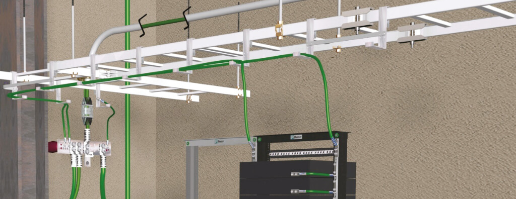
When racks, cabinets, or panels contain active equipment or metallic telecommunications cabling, NBR 17040 establishes their connection to the applicable equipotential bonding system. Each rack should have its own connection point and its own RBC — Rack Bonding Conductor.
A particularly relevant requirement for design and supervision is that racks must not be interconnected in series to form the equipotential bonding path. Series connections mean that removal, maintenance, or failure of one connection can compromise downstream elements.
Within the rack, electrical continuity should not be assumed simply because the parts are metallic. Structures assembled with screws, paint, coatings, and moving components may not provide reliable continuity unless they were designed to do so by the manufacturer.
Doors, panels, trays, organizers, and other metallic components may require their own bonding connections. Moving parts need to maintain continuity without relying solely on hinges or incidental mechanical contact.
The practical consequence is that rack detailing must appear in the design. A generic ground symbol beside the rack does not indicate where the RBC terminates, how the internal bonding bar is configured, which components are connected, or how continuity will be verified.
Cable Trays, Ladders, and Metallic Pathways Are Part of the Assessment
Continuous conductive pathway systems serving spaces with a BEPT or BELT that are not otherwise connected to the protective or telecommunications system should be integrated according to the criteria of NBR 17040.
This includes assessment of cable trays, cable ladders, conduits, and other metallic elements that run through the infrastructure. Continuity of these components should not be assumed from appearance alone. Joints, paint, oxidation, accessories, vibration, and maintenance interventions can change electrical behavior.
The design of pathway infrastructure for structured cabling therefore needs to coordinate mechanical and electrical aspects: support, fill, circuit separation, pathway continuity, bonding points, and interfaces with technical rooms.
The same caution applies to building metallic structures. NBR 17040 allows a suitable metallic structure to participate in the equipotential bonding architecture and, under specific conditions, to replace backbone elements. This requires design review, proof of continuity, and testing; it is not authorization to assume that any column, profile, or bolted structure is electrically continuous.
Star, Ring, and Mesh Topologies: Why Does Geometry Matter?
In telecommunications, the physical path of connections influences common-mode impedance and behavior in the presence of electromagnetic interference. For this reason, NBR 17040 does not simply address “connecting everything to ground”; it addresses different equipotential bonding topologies.
In a star topology, each piece of equipment or equipment group is connected to a main point. This architecture is easy to understand and maintain, but long routes can increase common-mode impedance and enlarge the loop area associated with interconnected equipment.
In a ring topology, equipment connects to an equipotential bonding conductor that runs through the space. Additional connections can reduce impedance and improve overall performance.
In mesh topologies, the density of interconnections is increased. NBR 17040 recognizes MESH-BN and MESH-IBN architectures, as well as resources such as supplementary bonding grids and signal reference planes. In high-density rooms such as data center environments, a mesh can provide superior bonding performance and greater immunity to interference.
When a building has a lightning protection system, NBR 17040 establishes a specific interface with mesh equipotential bonding. This decision must be coordinated with the SPDA design and cannot be resolved solely within the network discipline.
Ground Loops and Common-Mode Impedance
The expression “ground loop” is often used imprecisely. In NBR 17040, it relates to the path through which common-mode noise current can circulate between points at different potentials.
The existence of multiple metallic connections in a modern network is normal: equipment receives electrical power, has PE connections, is interconnected by metallic cables, may be mounted in racks, and may have connected shields. The engineering objective is not to indiscriminately eliminate all connections, but to control the architecture in order to reduce potential differences and unwanted impedances.
This explains why simplistic solutions such as “ground everything at a single point” or “always connect the shield at only one end” cannot be treated as universal rules. Topology, the predominant interference frequency, cabling type, equipment, and electrical interfaces all change the response.
The broader discussion of capacitive, inductive, and radiated coupling and noise control is available in the content on electromagnetic compatibility in cabling and electronic systems.
How Should Shielded Cables Be Grounded?
NBR 17040 dedicates a specific section to equipotential bonding and grounding of telecommunications cable shields. The central point is that there is no single method suitable for every interference scenario.
In shielded balanced cabling, the system needs to preserve shield continuity throughout the link and use compatible hardware. Cables, patch panels, and outlets should be specified consistently with the shielding strategy; mixing components without evaluating continuity can compromise the expected performance of the channel.
The standard discusses methods in which the shield is grounded in the telecommunications space and methods in which it is connected at both ends. The choice is related to the type of interfering field, the bonding topology, ground-loop risk, and the application.
Electric and magnetic fields do not produce the same effects. Cable shielding and balance also behave differently depending on frequency. Therefore, the statement “a shielded cable should be grounded at only one end” is not a general design rule.
For metallic backbones interconnecting different spaces, the analysis deserves additional attention because the ends may be associated with different electrical references. In industrial environments, substations, large plants, or buildings with substantial physical dispersion, the choice between copper and fiber may even be influenced by the need to reduce conductive paths between areas.
Does Fiber Optics Eliminate the Need for Equipotential Bonding?
No. Optical media is dielectric when it contains no metallic elements and, in the NBR 17040 selection table, optical cabling does not receive the same equipotential bonding requirements that apply to metallic cabling. This is an important advantage for galvanic isolation between areas.
However, optical infrastructure still uses racks, optical distribution frames, cabinets, metallic pathways, power supplies, switches, converters, transceivers, and other equipment. In addition, some optical cables contain armor, metallic strength members, or other conductive components.
Therefore, the decision needs to distinguish between the optical transmission medium and the metallic elements associated with the installation. The mere presence of fiber does not make the technical room electrically independent.
Telecommunications Entrance, SPDs, and Surge Protection
The telecommunications entrance room is a critical point because external lines, metallic elements, and building interfaces converge there. NBR 17040 seeks to reduce surge voltages and the effects of currents entering the building by bringing the entry points of different conductive elements closer together and coordinating their equipotential bonding.
Cables or signal lines entering from outside may require a specific telecommunications SPD compatible with the transmission class and the connected system. A power SPD installed in an electrical panel does not automatically replace protection for data lines.
The content on SPDs for data, video surveillance, automation, and telecommunications lines explains this interface in detail. Protection needs to be coordinated with equipotential bonding so that the device is not installed as an isolated component without an appropriate path for surge current.
When an SPDA is present, the interfaces among external lines, equipotential bonding, surge protection, and protection zones need to be addressed together. In new designs, these decisions should appear as early as the concept phase; in retrofits, they should be part of the assessment of the existing system.
At the telecommunications entrance, external lines, the SPDA, power SPDs, and signal SPDs need to be coordinated as a system. When this interface is addressed in isolation, surge paths may remain among power supplies, shields, structures, and network equipment.
What Should a Network Equipotential Bonding Design Include?
A consistent design needs to convert the normative architecture into executable and verifiable information. The document should not be limited to a generic note stating “ground racks according to the standard.”
The scope should define, as applicable:
- identification of the BEP and interfaces with the electrical installation;
- whether BEPT and BELT are required;
- topology of the telecommunications equipotential bonding system;
- routes and sizing of TBB, BBC, TBC, RBC, and other conductors;
- rack bonding bars and connection points;
- equipotential bonding of doors, panels, trays, and moving components;
- treatment of cable trays, cable ladders, conduits, and metallic structures;
- strategy for cable shields and connecting hardware;
- interfaces with electrical panels, PE, and equipment power supplies;
- interfaces with power and signal SPDs;
- interface with the SPDA when present;
- identification, labeling, and accessibility criteria;
- connection methods and corrosion protection;
- inspection plan, tests, and acceptance criteria;
- photographic documentation and As-Built requirements.
In a Structured Cabling Design, these elements need to be coordinated with network topology, distributor locations, technical rooms, backbone, pathways, and spaces. When the electrical infrastructure has deficiencies, an additional diagnostic or grounding design scope may be required before deployment.
How Should the System Be Inspected and Tested?
Acceptance should not be based on visual inspection alone. NBR 17040 establishes DC resistance measurements between points in the architecture and requirements for evaluating system performance.
Before continuity testing, the standard calls for a visual inspection and verification of conditions that could make the test unsafe or invalid. The presence of active equipment and parallel paths can also affect results; therefore, test planning needs to consider the actual state of the installation.
A verification campaign should record at least:
- tested points and their physical identification;
- instrument and calibration status;
- method used;
- stated accuracy or uncertainty of the measurement;
- results obtained;
- installation condition during the test;
- photographic evidence;
- nonconformities and recommendations;
- comparison with design and As-Built documentation.
Documentation is part of the system. NBR 17040 recommends adequate records and photographic documentation so that future maintenance can identify removed connections, oxidation, rack modifications, and topology changes.
In the absence of a specific electrical maintenance schedule, Annex A of the standard recommends annual visual inspection and a complete inspection every three years, including measurements and system evaluation. In critical installations or aggressive environments, the maintenance plan may require a different frequency.
Apparent continuity does not prove equipotential bonding performance. When acceptance depends on resistance measurements, connection verification, traceability, and evidence, the test plan needs to define points, method, calibration, and criteria before the field campaign.
How Should an Existing Installation Be Diagnosed?
In an existing network, starting by installing new bonding conductors can mask the problem instead of solving it. The diagnosis should first reconstruct the actual architecture.
An efficient technical sequence is:
- identify the BEP and the grounding arrangement of the electrical installation;
- locate entrance rooms and other telecommunications spaces;
- map racks, cabinets, panels, and metallic pathways;
- identify existing connections and points without verified continuity;
- verify equipment power supply and PE arrangements;
- map the TBB, local bonding bars, and any structures used as bonding paths;
- identify shielded cabling and the adopted termination method;
- verify external lines and signal SPDs;
- inspect interfaces with the SPDA and metallic structures;
- plan continuity and DC resistance tests;
- correlate any network symptom with electrical measurements and telecommunications tests before assigning a cause.
When there are recurring port failures, failures after storms, currents in shields, perceptible potential differences, undocumented legacy interventions, or behavior that depends on connections between buildings, the investigation should be multidisciplinary. The electromagnetic interference diagnosis and mitigation service can complement the analysis when the problem goes beyond simple electrical continuity.
Common Errors in Network Grounding and Equipotential Bonding
Some errors recur in designs, retrofits, and existing installations:
- installing a dedicated ground rod for the rack without assessing the building’s equipotential bonding system;
- treating an “IT ground” as a necessarily isolated system;
- connecting racks in series, using one rack as the path to the next;
- assuming electrical continuity in bolted racks, cable trays, or painted structures;
- using the cable shield as a substitute for equipotential bonding conductors;
- applying the rule “ground the shield at one end only” without analyzing topology and interference type;
- selecting conductor sizes without considering length, impedance, and architecture;
- creating long, coiled, or unnecessarily bent routes;
- failing to coordinate the telecommunications entrance with SPDs, the BEP, and external metallic lines;
- treating grounding-electrode resistance measurement as the only acceptance criterion;
- attributing every network failure to grounding without evidence of causation;
- failing to maintain documentation, conductor identification, and test records.
Corrective action requires understanding the system as an electrical equipotential bonding network rather than as a collection of green wires connected to metallic points.
Final Considerations
Grounding and equipotential bonding in network infrastructure form an interface discipline between telecommunications and electrical engineering. ABNT NBR 17040:2022 provides a specific architecture for this interface and replaces the simplified approach in which racks and equipment were treated merely through a generic list of “ground points.”
A technically robust solution begins with assessment of the existing protective equipotential bonding system. From there, it is determined whether the system is sufficient, whether supplementary measures are needed, or whether the installation requires a dedicated architecture with BEPT, BELT, TBB, and local connections. Racks require individual bonding connections; metallic pathways, structures, and shields require specific criteria; SPDs and the SPDA need to be coordinated; and acceptance depends on inspection, testing, and documentation.
For new networks, this architecture should be integrated from the outset with the structured cabling design and electrical disciplines. For existing networks, the best intervention begins by diagnosing the actual topology, avoiding the creation of additional connections without understanding the current paths that already exist.
When an existing installation shows recurring failures, currents in shields, or a history of undocumented interventions, adding connections without a diagnosis can create new current paths. The survey should reconstruct the actual topology before defining corrective action.
Learn about the Interference Diagnosis and Mitigation service
Technical references
[1] ASSOCIAÇÃO BRASILEIRA DE NORMAS TÉCNICAS. ABNT NBR 17040:2022 — Equipotencialização da infraestrutura de cabeamento para telecomunicações e cabeamento estruturado em edifícios e outras estruturas. Rio de Janeiro: ABNT, 2022. Available at: https://www.dinmedia.de/en/standard/abnt-nbr-17040/355815933
[2] ASSOCIAÇÃO BRASILEIRA DE NORMAS TÉCNICAS. ABNT NBR 5410 — Instalações elétricas de baixa tensão. Rio de Janeiro: ABNT. Available at: https://www.abntcatalogo.com.br/
[3] ASSOCIAÇÃO BRASILEIRA DE NORMAS TÉCNICAS. ABNT NBR 14565:2025 — Cabeamento estruturado para edifícios comerciais. Rio de Janeiro: ABNT, 2025. Available at: https://www.dinmedia.de/en/standard/abnt-nbr-14565/398016475
[4] ISO/IEC. ISO/IEC 30129:2015 — Information technology — Telecommunications bonding networks for buildings and other structures, with Amendments 1:2019 and 2:2025. Available at: https://www.iso.org/standard/53249.html
Frequently asked questions
Not as a general rule. The rack should be integrated into the applicable equipotential bonding architecture. Creating an isolated electrode without coordinating it with the BEP and the rest of the installation can increase potential differences. The solution should follow the existing protective system and, when necessary, the telecommunications architecture defined by NBR 17040.
The BEP is the building’s main equipotential bonding bar. The BEPT is the main telecommunications equipotential bonding bar of a dedicated system and connects to the corresponding BEP. The BELT is the local bonding bar serving a telecommunications space and connects to the BEPT through the bonding backbone.
When a rack, cabinet, or panel contains active equipment or metallic cabling and is covered by the equipotential bonding system, NBR 17040 establishes a dedicated connection through an RBC. Racks should not be daisy-chained in series as an equipotential bonding path.
There is no universal rule. NBR 17040 describes different methods depending on the subsystem, bonding topology, and nature of the interference. The strategy should preserve shield continuity and consider electric fields, magnetic fields, and ground-loop risk.
No. Dielectric fiber does not create the same conductive path as metallic cabling, but racks, cabinets, metallic pathways, power supplies, switches, and any metallic cable elements remain subject to equipotential bonding assessment.
No. Electrode resistance is only one part of the assessment. The architecture, continuity, connection resistance, BEP and bonding bars, racks, metallic pathways, shields, SPDs, and interfaces with the electrical system also need to be verified.
Symptoms need to be correlated with electrical measurements, inspection of equipotential bonding, and telecommunications tests. Packet loss or intermittent failures can also result from cabling, power, PoE, configuration, firmware, or equipment issues; they should not be attributed to grounding without evidence.
Complementary technical materials
Related solutions
- Grounding and Equipotential Bonding: SPDA, SPDs, NBR 5410, and technical documentation
- Surge Protection Measures: architecture and protection of internal systems
- Electromagnetic Compatibility and Interference Control
Related services
- Grounding Design: SPDA, SPDs, equipotential bonding, and technical documentation
- Grounding Technical Report: technical measurements, ART, SPDA, and documentation
- SPDA Technical Report: NBR 5419, inspection, grounding, SPDs, and upgrading
- Surge Protection Measures Design
- Technical Testing and Verification
- Electromagnetic Interference Diagnosis and Mitigation
Main content on the topic
- Equipotential Bonding: what it is, BEP, BEL, grounding, and NBR 5410
- Electrical Grounding: what it is, types, arrangements, and NBR 5410
- SPDs for Data, Video Surveillance, Automation, and Telecommunications Lines
Related technical content
- Equipotential Bonding in SPDA: NBR 5419-3:2026, BEP, BEL, SPDs, and internal protection
- NBR 5419-4:2026: surge protection measures, LPZ, SPDs, and protection of electrical and electronic systems
- SPDs and Circuit Breakers: backup protection, sizing, and installation
- Complete Guide to Lightning Protection (SPDA + Surge Protection Measures)
