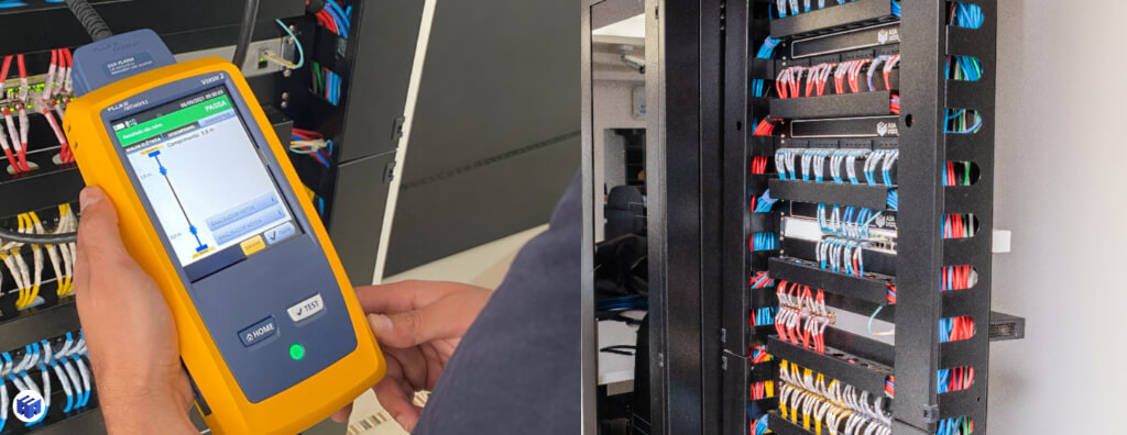
Learn how to certify a structured cabling network: Permanent Link vs Channel, certifier configuration, parameters, PASS/FAIL, retesting, reports, and acceptance criteria.
Check it out!
Certifying a structured cabling network means verifying, through field testing, whether the installed links meet the performance limits defined for the class, category, and configuration specified in the design. It is not merely testing continuity, measuring “internet speed,” or printing a report with a PASS result. A technically valid certification process starts before the first test: it requires defining the test object, identifying the links, selecting the correct normative limit, using compatible instruments and adapters, calibration, controlled execution, failure interpretation, retesting, traceability, and integration of the results into the As Built.
In a professional project, certification serves as acceptance evidence for the physical layer. It demonstrates that the installed link delivers performance compatible with what was specified and creates a baseline for maintenance and future interventions. The value of the process lies both in the measurements and in the ability to reconstruct later how, when, and with what configuration each link was tested.
What does it mean to certify a structured cabling network?
A network certifier is a field test instrument that measures electrical parameters across the applicable frequency range and compares the results with normative limits. Unlike a simple tester, it is not limited to indicating whether conductors are connected. Its purpose is to evaluate the performance of the installed link against a defined class or category.
The certifier also does not “turn” a cable into Cat6 or Cat6A. A cable marked Cat6 may be part of a failing link if connectors, termination, length, installation, or components compromise performance. Likewise, a certification result is only technically meaningful when the selected limit corresponds to the system actually contracted.
For this reason, certification should be understood as a verification process rather than an isolated operation of the instrument.
Certifier, tester, verifier, and qualifier are not the same thing
Different tools answer different questions. A continuity tester can detect open conductors, shorts, reversals, or wire-map faults. A qualifier can assess whether a given Ethernet application is likely to operate. A certifier measures the parameters required to compare the link with category/class limits defined by the applicable standards.
Using a simple tester to “certify” a project is a scope error. Continuity is necessary, but it does not demonstrate insertion loss, crosstalk, return loss, and the other transmission parameters required for acceptance of structured infrastructure.
Define the test object before turning on the certifier
Permanent Link, Channel, and MPTL represent different test objects. The acceptance method must originate in the design so the installation is built and tested according to the same architecture.
The first decision is to define exactly what will be certified. The test model must represent the physical configuration being accepted. Permanent Link, Channel, and MPTL are not synonyms.
| Configuration | What it represents | Typical use |
| Permanent Link | fixed section between permanent terminations | acceptance of installed fixed cabling |
| Channel | fixed infrastructure plus the intended cords | validation of the configured complete channel |
| MPTL | fixed link terminated directly with a modular plug at one end | cameras, APs, and other fixed devices when specified |
| direct connection | specific configuration without conventional outlet/patch-panel architecture | dedicated applications defined in the design |
Selecting Channel to accept a Permanent Link, or applying a Permanent Link limit to an MPTL configuration without the corresponding adapters, changes the meaning of the result.
The design must define this condition before construction. If the team only decides the test model at closeout, there is a risk that the installed infrastructure will not correspond to the acceptance method.
The article on MPTL explores the configuration terminated directly with a modular plug in greater depth.
Step 1 — Check the design, identification, and link matrix
Before the first test, there should be a controlled list of the links to be certified. This matrix reduces omissions, duplicates, and naming errors.
Each link needs a unique identifier consistent with the physical condition. A convention may combine building, floor, technical room, rack, patch panel, and port. The specific format varies by project, but the logic must remain consistent.
The same identification should appear, whenever applicable, on:
- outlet or terminal point;
- cable and both ends;
- patch panel and port;
- drawing or As Built;
- link matrix;
- certifier file;
- PDF report;
- maintenance records.
A3A Engenharia’s technical knowledge base reinforces that a technically correct report loses value when the link name does not match the drawing, patch panel, or installed label. Traceability must exist end to end.
Identification must be defined before testing
Renaming hundreds of reports after certification increases the risk of incorrectly associating a result with the physical link. Ideally, the naming convention should be loaded or configured in the instrument before the test campaign.
It is also advisable to compare the planned matrix with the quantity actually installed. If the design expected 300 outlets and the reports contain 287 results, the difference must be explained before acceptance—not simply ignored because all 287 show PASS.
Step 2 — Define the standard, class, category, and test limit
The certifier needs to know which limit to use when comparing measurements. This choice must derive from the design and technical specification.
An installation contracted as Class E/Cat6 should not be arbitrarily tested as Cat5e because it “passes more easily.” Likewise, selecting Cat6A on infrastructure that was not designed and supplied as Class EA does not create additional compliance; it merely applies a limit that may not represent the contracted object.
ABNT NBR 14565 is a central Brazilian reference for cabling architecture in commercial buildings, while the NBR 16869 series complements planning, installation, testing, special configurations, identification, and administration.
The limit must be standardized across the entire lot
If two technicians test equivalent links using different limits, the results are no longer directly comparable. The test plan should record in advance:
- applicable standard and limit;
- configuration: Permanent Link, Channel, MPTL, or other;
- category/class;
- cable type and shielding;
- adapters to be used;
- policy for PASS, FAIL, and marginal results;
- lot and link identification.
This standardization is one of the simplest ways to increase the reliability of the test campaign.
Step 3 — Select the instrument, adapters, and calibration
The instrument must have metrological capability compatible with the class and configuration being tested. Simply having a “network certifier” is not enough. Different models may have different frequency ranges, accuracy levels, adapters, and supported limits.
Families such as Fluke Networks DSX, TREND Networks LanTEK, and Softing WireXpert are well-known examples of field equipment. They should not, by themselves, become a brand requirement. Suitability must be verified by performance, accuracy, range, adapters, calibration, and the ability to generate traceable reports.
Calibration and verification are not administrative details
The calibration status of the instrument and accessories must be verifiable. A technically sophisticated measurement loses strength as evidence if there is no control over the equipment used.
Before testing, record:
- manufacturer and model of the main and remote units;
- serial numbers;
- adapters used;
- validity or evidence of applicable calibration;
- firmware version and limit database when relevant;
- operator;
- campaign date.
Adapters also matter. Permanent Link, Channel, and MPTL may require specific accessories. An unsuitable adapter can introduce elements into the circuit that do not belong to the configuration being evaluated.
Step 4 — Perform a visual inspection before certification
Certification does not replace physical inspection. A link may obtain PASS and still have construction issues that need correction: poor identification, unsupported cable, excessively tight bend radius, saturated pathways, lack of organization, or workmanship inconsistent with the design.
Before starting the campaign, check:
- apparent cable integrity;
- absence of crushing and severe bends;
- bend radius;
- termination and amount of untwisting;
- rack organization;
- fixing and support along pathways;
- identification at both ends;
- shield continuity where applicable;
- compatibility among components;
- condition of patch panels and outlets.
This inspection reduces rework because visible problems can be corrected before generating a long sequence of FAIL results.
Step 5 — Configure the certifier in a controlled manner
A3A Engenharia’s technical knowledge base recommends that the test plan define all basic configuration parameters before the first link. This prevents each operator from adjusting the instrument independently.
A campaign configuration should include:
- standard and limit;
- link type;
- category/class;
- cable type and any shielding;
- link naming convention;
- adapters;
- main and remote units;
- calibration/verification status;
- operator and date;
- policy for PASS, FAIL, and marginal results.
When possible, use templates or internal projects in the certifier software itself to reduce manual variation among tests.
Step 6 — Execute copper cabling tests
The parameters evaluated depend on the class, configuration, and selected limit. In copper cabling, a certification campaign may include wire map, length, insertion loss, NEXT, PSNEXT, return loss, ACR ratios, delay, and other quantities required by the selected reference.
The article Network Cable Certification Parameters explores each parameter in more detail. For the certification process, the main point is that the final PASS results from comparison of a set of measurements—not a single test.
Wire map and continuity
The wire map checks conductor correspondence and helps identify open pairs, shorts, reversals, crossed pairs, or split pairs. It is a basic but essential verification.
A network can have electrical continuity and still fail transmission parameters. Therefore, an approved wire map is not equivalent to completed certification.
Length
Length measurement helps verify whether the link remains within the limits for the configuration. Excessive lengths can compromise insertion loss and delay and may also indicate route deviations or poorly controlled cable slack.
Unexpected differences among pairs may also indicate physical problems or improper termination.
Insertion loss
Insertion loss represents the reduction in signal power along the link. It increases with distance, frequency, and the characteristics of the medium and connections.
Results close to the limit deserve analysis, especially when combined with long lengths, operating temperature, or many connection elements.
NEXT and PSNEXT
NEXT evaluates near-end crosstalk between pairs. PSNEXT considers the combined contribution of multiple interfering pairs. Problems may be associated with excessive untwisting, improper termination, low-quality components, or category incompatibility.
Return loss
Return Loss is related to reflections caused by impedance discontinuities along the link. Connectors, deformation, transitions, and improper assembly can affect the result.
A return-loss failure may require more careful analysis because the problem is not always visible at the endpoint.
ACR ratios and other parameters
Ratios such as ACR derive from the interaction between useful signal and interference and help evaluate the operating margin of the link. Delay and delay skew among pairs are also relevant for certain applications and limits.
The certifier automates comparison, but the professional must still interpret the source of a failure and verify that the selected limit is correct.
How to interpret PASS, FAIL, and margin
PASS means that, for the selected configuration and limit, the evaluated parameters remained within the instrument criteria. This does not mean every aspect of the network is perfect.
FAIL indicates that at least one requirement was not met and requires investigation. The result should be associated with the parameter, frequency, pair, and margin involved.
Marginal results deserve attention
Some instruments may indicate a condition close to the limit or low margin. Even when the final result is accepted under the configured rule, a very small margin may be relevant in critical environments or links subject to temperature, movement, or future changes.
The technical specification should define how marginal results are handled. The objective is not to create arbitrary criteria after measurement, but to establish the acceptance policy in advance.
How to handle a FAIL without replacing everything by trial and error
A failure should be investigated according to the failed parameter. The objective is to locate the most probable cause before indiscriminately replacing components.
A rational sequence may be:
- confirm that the test limit and configuration are correct;
- check certifier adapters and connections;
- inspect terminations at both ends;
- evaluate connectors and patch panel;
- check bend radius, crushing, and mechanical stress;
- analyze route, interference, and environmental conditions;
- correct the identified cause;
- retest the link;
- preserve the intervention history.
The simplest failure may be at a termination. Others require investigation of the cable or route. Replacing an entire patch panel without evidence increases cost and may introduce new defects.
Retesting must remain traceable
When a failed link is corrected, the new result must be associated with the same identifier and the intervention history. Silently deleting the previous FAIL and delivering only the final PASS reduces process traceability.
In audits or commissioning, the history helps explain the amount of rework, recurring causes, and implementation quality.
Optical fiber certification requires a different test set
Optical cabling is not certified using the same parameters as copper. The scope may include optical-loss measurements and, depending on the design and acceptance criteria, OLTS/LSPM and OTDR testing, as well as connector inspection and cleaning.
ABNT NBR 16869-2 is one of the Brazilian references related to optical cabling tests. The method, wavelengths, references, test cords, test direction, and interpretation criteria must be defined in the test plan.
It is not appropriate to apply a generic rule such as “every fiber requires OTDR” without considering what was specified and what evidence is needed. In some contracts, OLTS and OTDR have complementary roles: one measures end-to-end loss and the other provides information along the link, useful for locating events.
Connector cleaning and inspection affect the result
Contaminated optical connectors are a recurring source of loss and instability. The campaign should include inspection and cleaning practices before measurements, avoiding treating contamination as a permanent fiber defect.
Optical documentation must also maintain the same identification logic applied to copper: origin, destination, fiber, port, optical distribution frame, and link must remain traceable.
Certification report: what it needs to contain
The report must allow the test to be reconstructed: limit, configuration, instrument, calibration, parameters, and link identification must remain traceable.
An acceptance report must allow another person to reconstruct the test. A3A Engenharia’s technical knowledge base lists important fields including:
- unique link identification;
- selected standard and limit;
- test configuration;
- category or class;
- cable type;
- measured length;
- results for all required parameters;
- margin and worst case where applicable;
- manufacturer, model, and serial number of the instrument;
- adapter identification;
- calibration or verification;
- date and operator;
- final result;
- retest history when corrections occurred.
A PDF showing only the outlet name and PASS does not provide the same level of evidence.
The certifier’s native file is an important part of the handover
The technical knowledge base, based on NBR 16869-1, highlights delivery of field results in the equipment’s native electronic format and the possibility of PDF reports when specified.
The native file preserves structured data, test configuration, measurements, and metadata that may not appear in the PDF. It allows the test to be reopened in the corresponding software, limits to be reviewed, and record consistency to be verified.
A robust certification package may contain:
- native instrument files;
- consolidated PDF reports;
- master link matrix;
- map of PASS, FAIL, and retests;
- certificate or evidence of calibration;
- list of instruments and adapters;
- operator and date identification;
- correction records;
- optical documentation and OTDR traces when specified.
This set strengthens the Data Book and technical acceptance.
Traceability: report, rack, port, and As Built must match
Certification only becomes an operational asset when the result can be associated with the physical infrastructure. A file called “POINT-023” is of limited value if the drawing shows “3P-R02-PP01-23” and the outlet uses yet another identifier.
NBR 16869-1 treats identification and records as part of cabling administration. The database can relate cable, terminations, pathways, spaces, equipment, and certification date.
This consistency makes it possible to:
- quickly locate a failed link;
- compare the result with the physical route;
- know which patch-panel port corresponds to the test;
- record future interventions;
- demonstrate that the As Built represents the delivered network;
- recertify only links affected by a change when technically applicable.
The Engineering As Built should therefore be treated as part of the network closeout package.
Technical acceptance criteria must exist before the campaign
Acceptance should not be decided after reviewing the results. The design, specification, or contract must define what constitutes an approved delivery.
Typical criteria to specify include:
- which links are in scope;
- which class/category will be verified;
- which test configuration will be used;
- which standards and limits apply;
- instrument and calibration requirements;
- report format;
- need for native files;
- handling of FAIL results and retests;
- identification consistency;
- As Built documentation;
- responsibility for corrections.
The number of links to be tested must also be defined. Sampling should not be assumed when the contract requires full certification, nor should a percentage be invented after execution.
How to specify the service without locking in a certifier brand
The specification should require metrological and functional capability, not simply “use Fluke.” The technical knowledge base cites Fluke DSX, TREND LanTEK, and Softing WireXpert as examples of existing families, but equivalence depends on verifiable requirements.
A technically neutral clause may require:
- instrument compatible with the class and tested frequency range;
- accuracy suitable for the applicable standards;
- adapters compatible with Permanent Link, Channel, or MPTL as required by scope;
- valid and traceable calibration;
- support for the selected normative limit;
- generation of a native file and complete report;
- instrument identification and serial number;
- ability to export results in an auditable format.
This model increases competition without reducing technical rigor.
Network certification in contracts and public works
In formal contracts, certification must be connected to the object, design, and acceptance process. The issue is not merely “having a report,” but verifying whether the document demonstrates the contracted requirement.
A technically verifiable certification scope may define:
| Requirement | What to specify |
| scope | number of links, locations, and systems |
| class/category | Class D, E, EA, or other applicable class |
| configuration | Permanent Link, Channel, MPTL, etc. |
| instrument | compatible performance, accuracy, and range |
| calibration | valid and traceable evidence |
| reports | native file + PDF where applicable |
| failures | correction, responsibility, and retest |
| deliverables | consolidated matrix, results, and As Built |
| acceptance | objective approval criteria |
This allows inspection teams and contractors to know in advance which evidence will be required.
When certification should occur during construction
Leaving all certification until the last day concentrates rework risk. On large projects, it is more efficient to test by area, floor, or lot as terminations are completed and protected.
This strategy makes it possible to identify failure patterns while the team is still mobilized. If a particular termination procedure is generating high NEXT, for example, the correction can be applied to subsequent lots before hundreds of outlets are completed.
Intermediate tests, however, do not eliminate the need to ensure that the final delivered condition matches the result. Subsequent changes, component replacement, or damage after testing may require new verification.
When to recertify an existing network
Not every change requires full recertification, but there are situations in which new tests are technically relevant:
- retrofit of cables or connectors;
- retermination of links;
- significant route change;
- replacement of patch panels or outlets;
- intermittent failures without a known cause;
- expansion of old infrastructure without reliable test history;
- migration to more demanding applications;
- changes affecting MPTL or channel configuration;
- absence of previous certification documentation.
The scope may be directed to the affected links or expanded according to criticality and installation condition.
A Technical Due Diligence can help define the required extent in brownfield environments.
Certification does not replace commissioning and quality inspection
Certification primarily answers the performance of the tested link. By itself, it does not confirm that the entire infrastructure has been correctly implemented.
Complete acceptance may also need to verify:
- pathway occupancy and workmanship;
- segregation and coordination;
- rack organization;
- physical identification;
- grounding and equipotential bonding;
- expansion reserves;
- documentation and As Built;
- compliance with the design;
- environmental conditions;
- integration with equipment and systems when included in scope.
For this reason, certification should be included in a broader process of inspection, testing, and commissioning, especially for critical networks.
Common mistakes when certifying a network
Using a continuity tester as if it were a certifier
It can demonstrate basic connectivity but does not show compliance with the transmission limits of the class or category.
Selecting the wrong limit
Applying a lower limit than contracted masks nonconformity; applying a higher limit without justification tests something different from the specified object.
Testing the wrong configuration
Permanent Link, Channel, and MPTL require compatible interpretation and adapters. The option selected in the instrument menu must correspond to the physical link.
Ignoring calibration and accessories
An instrument without metrological control weakens the value of the result. Worn adapters can also affect measurements.
Delivering only a summarized PDF
Without the native file, part of the metadata and measurements may be unavailable for future audit.
Inconsistent identification
Reports that do not correspond to outlets, racks, and drawings make it difficult to prove which link was actually tested.
Deleting FAIL history
The handover should preserve traceability of corrections when this is part of the project control process.
Treating PASS as the only quality criterion
An approved link may coexist with poor identification, an unsuitable pathway, a saturated rack, or incomplete documentation. Certification is important evidence, but it is not the entire inspection process.
Structured cabling certification checklist
Before closing the campaign, confirm:
- Is there a complete matrix of the links in scope?
- Does each link have unique identification consistent with the physical installation?
- Are the standard and limit documented?
- Were Permanent Link, Channel, or MPTL correctly defined?
- Does the category/class correspond to the design?
- Does the instrument support the required range and limit?
- Were the correct adapters used?
- Are calibration and instrument identification recorded?
- Were all required parameters measured?
- Were FAIL results investigated, corrected, and retested?
- Is the correction history traceable?
- Were native files preserved?
- Are PDFs and the results matrix complete?
- Does report identification match patch panels, outlets, and drawings?
- Does the As Built incorporate the final condition?
- Were specified optical tests performed using the required method?
- Does the final package allow another team to reconstruct the test process?
If any of these answers is negative, the installation may not yet be ready for technical acceptance even if some reports show PASS.
How to audit reports received from a contractor
Inspection does not need to rely solely on the summary provided. A technical review can select records and verify consistency among native files, PDFs, the matrix, and the physical condition.
Some consistency checks are simple and effective:
- compare total number of links with the design and As Built;
- look for duplicate identifiers;
- verify that all records use the same limit;
- check dates, instruments, and calibration;
- identify FAIL/retest sequences;
- compare measured lengths with plausible routes;
- physically validate samples at the rack and outlet;
- verify that the native file opens and contains complete measurements.
This type of audit identifies problems that do not appear in a consolidated spreadsheet of “approved” links.
Certification creates a baseline for operations
After acceptance, the results serve as a historical reference. If a link begins to fail years later, a new measurement can be compared with the original condition to assess degradation, termination changes, or physical damage.
This value only exists when files are preserved in an organized manner. If reports are scattered across emails, without consistent identification or native format, the organization loses part of the information produced during the project.
Integrating certification, As Built, and asset management improves infrastructure governance and reduces diagnostic cost throughout the lifecycle.
Final considerations
Certifying a structured cabling network is an engineering verification and acceptance process. The equipment is only one part. The technical validity of the result depends on the design, correct test configuration, identification, compatible instrument and adapters, calibration, controlled execution, failure interpretation, retesting, and traceable documentation.
A well-conducted certification campaign answers an objective question: does the installed physical infrastructure meet the requirements defined for the contracted system? To answer with confidence, the handover package must allow another team to reconstruct the test and relate each result to the corresponding physical link.
When complete reports, native files, the link matrix, and As Built documentation are integrated, certification stops being merely a closeout document and becomes durable technical evidence for inspection, maintenance, auditing, and future expansions.
Certification, As Built, and final documentation must converge on the same installed condition. Together, they transform field results into acceptance evidence and an operational reference.
Technical references
[1] ASSOCIAÇÃO BRASILEIRA DE NORMAS TÉCNICAS. ABNT NBR 14565: Cabeamento estruturado para edifícios comerciais. Rio de Janeiro: ABNT. Available at: https://www.abntcatalogo.com.br/
[2] ASSOCIAÇÃO BRASILEIRA DE NORMAS TÉCNICAS. ABNT NBR 16869-1: Cabeamento estruturado — Parte 1: requisitos para planejamento. Rio de Janeiro: ABNT. Available at: https://www.abntcatalogo.com.br/
[3] ASSOCIAÇÃO BRASILEIRA DE NORMAS TÉCNICAS. ABNT NBR 16869-2: Cabeamento estruturado — ensaios de cabeamento óptico. Rio de Janeiro: ABNT. Available at: https://www.abntcatalogo.com.br/
[4] ASSOCIAÇÃO BRASILEIRA DE NORMAS TÉCNICAS. ABNT NBR 16869-3: Cabeamento estruturado — configurações especiais, incluindo MPTL. Rio de Janeiro: ABNT. Available at: https://www.abntcatalogo.com.br/
[5] INTERNATIONAL ORGANIZATION FOR STANDARDIZATION; INTERNATIONAL ELECTROTECHNICAL COMMISSION. ISO/IEC 11801: Information technology — Generic cabling for customer premises. Available at: https://www.iso.org/
Frequently asked questions
It is the process of measuring the parameters of an installed link and comparing them with the limits defined for the class, category, and configuration specified in the design.
No. It verifies basic connectivity and wire-map faults, but it does not measure the full set of transmission parameters required to compare the link with normative limits.
Permanent Link represents the fixed portion of the cabling between permanent terminations. Channel also includes the cords used in the complete configuration.
Yes, when the architecture specifies MPTL and the instrument has a compatible configuration and adapters for the applicable method.
Link identification, limit, configuration, category/class, length, measured parameters, margin, instrument, adapters, calibration, operator, date, result, and retest history where applicable.
Because it preserves structured data, configuration, measurements, and metadata that may not appear in the PDF and allows later auditing of the test.
Not necessarily. Acceptance may also require physical inspection, identification, documentation, As Built, pathways, racks, and other project requirements.
Not as a general rule. The specification should require metrological capability, range, accuracy, adapters, calibration, and reports compatible with the test, without locking in a brand when there is no technical justification.
After reterminations, retrofit, relevant changes, recurring failures, critical expansion, or when there is no reliable test history, according to the scope defined by engineering.
Additional technical resources
Related solutions
Related services
Core content on this topic
- Network Certification: process, tests, reports, and technical acceptance
- Network Cable Certification Parameters
