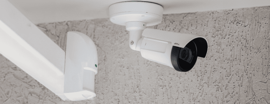
IP CCTV cabling: architecture, bitrate, Cat6/Cat6A, PoE, MPTL, fiber, outdoor cameras, certification, commissioning, and As-Built documentation.
Check it out!
Network cabling for IP CCTV is the physical infrastructure that connects cameras to switches, uplinks, the backbone, and recording and management systems. Its design must consider not only cable category but also bitrate and traffic peaks, Power over Ethernet, distance, environment, MPTL or conventional outlets, availability, pathways, electrical protection, identification, certification, and integration with the VMS architecture.
A 4K camera does not “require Cat6” simply because it is 4K, just as a lower-resolution camera does not automatically imply Cat5e. Video data rate depends on resolution, frames per second, compression, scene complexity, and bitrate configuration; the sum of these flows becomes especially relevant at aggregation points — switches, uplinks, backbones, servers, and storage. Horizontal-cabling category should be selected based on system requirements and lifecycle, not on a simplified megapixel rule.
In professional projects, the camera link is only one part of the solution. CCTV quality depends on continuity among security objectives, camera positioning, passive infrastructure, active networking, power, recording, retention, synchronization, operations, and technical acceptance.
How Cabling Fits into an IP CCTV Architecture
Cameras, PoE, switches, uplinks, VMS, storage, and security objectives need to be sized as a single system. The design defines interfaces before construction turns decisions into improvisation.
An IP video system can be understood in layers. At the edge is the camera, which captures and encodes video. The access link carries data and often PoE power. The switch aggregates multiple cameras. Uplinks and backbones carry traffic to servers, NVRs, VMS, storage, and operator workstations.
A typical architecture includes:
- IP camera or encoder;
- direct MPTL connection or telecommunications outlet;
- horizontal copper cabling;
- patch panel and patch cord in the technical room, where applicable;
- PoE access switch;
- copper or fiber uplink;
- aggregation backbone;
- server/NVR/VMS and storage;
- monitoring clients, integrations, and evidence export.
Each section has different requirements. An individual camera link may have significant bandwidth margin while the uplink of a switch with dozens of cameras approaches capacity. Likewise, the cable may carry data correctly while the camera still reboots because of an insufficient PoE budget.
Therefore, the IP CCTV and Video Surveillance Design must coordinate video, networking, power, recording, and physical infrastructure as a system.
Camera Bitrate Is Not the Same as Cable Category
In IP video, bitrate is the amount of data transmitted per unit of time. It depends on encoding configuration and scene content. Resolution, frame rate, compression, quality level, GOP, motion, noise, and analytics features can all change the amount of data produced.
This means two cameras with the same resolution can generate different traffic profiles. A static corridor scene may consume less bandwidth than an outdoor area with trees, rain, continuous movement, and variable lighting, even with similar nominal parameters.
VBR, CBR, and Traffic Peaks
In variable-bitrate mode, the encoder adjusts bitrate according to scene complexity. This improves efficiency but creates peaks that the network must absorb. In constant-bitrate mode, behavior is more predictable, but quality may vary according to the scene and configured limits.
Sizing should consider not only historical averages but also peak conditions and concurrency. A network designed exactly around average traffic can saturate during relevant events — precisely when the security system most needs to preserve video.
O artigo Bitrate Control in IP Video Systems explores VBR, CBR, compression, and their impacts on networking and storage in more depth.
Aggregation Is Where the Sum of Streams Becomes Critical
For an individual camera, the physical link often has capacity far above the video bitrate. Bandwidth becomes critical when multiple streams converge.
If a switch receives 24 or 48 cameras, the uplink must accommodate the sum of relevant streams, peak margins, management traffic, and other services. In larger architectures, multiple switches converge on a backbone, concentrating even more traffic.
The analysis should therefore distinguish:
| Section | Main sizing question |
| camera → switch | does the link support the application, PoE, distance, and environment? |
| switch → distribution | does the uplink support aggregate traffic and peaks? |
| distribution → core/VMS | does the backbone support all streams and redundancy? |
| VMS → storage | does the infrastructure support the planned recording and retention? |
| VMS → clients | are simultaneous viewing and exports accounted for? |
This separation prevents the horizontal-cable category from being treated as if it alone determined video-network performance.
Cat5e, Cat6, or Cat6A for CCTV: How to Decide Correctly
The category should result from the design. For new networks, Cat6 and Cat6A are often evaluated because they provide greater margin and better alignment with long lifecycles, but the decision depends on the architecture, not only the camera.
Relevant criteria include:
- intended speed and application class;
- distance and channel configuration;
- PoE and power requirements;
- service-life horizon;
- future cable-replacement feasibility;
- equipment density;
- electromagnetic environment;
- cable diameter and pathway occupancy;
- project standardization;
- planned certification and warranty.
Camera Resolution Should Not Be Used as a Category Rule
Associating “Full HD = Cat5e” and “4K = Cat6” is a technically weak simplification. Resolution affects bitrate, but not in isolation. Codec, frame rate, quality, scene, and rate-control settings also matter.
In addition, an infrastructure design must consider the future. Cabling usually remains installed longer than cameras. A camera may be replaced several times during the life of the passive infrastructure.
Therefore, the design should separate the current application from the desired performance reserve for the lifecycle.
Cat6A Can Make Sense Even When the Camera Does Not Use 10 Gb/s
The justification for Cat6A may lie in building standardization, service life, PoE, greater margin, future applications, or difficulty replacing the cabling — not in the camera consuming gigabits per second.
On the other hand, Cat6A typically uses larger-diameter cables and may require review of conduits, cable trays, boxes, connectors, and rack organization. Specifying a higher category without recalculating the physical infrastructure can compromise installation.
O Structured Cabling Design should coordinate these decisions with the security design.
MPTL or Telecommunications Outlet at the Camera?
Cameras are fixed devices and therefore represent a natural application for MPTL — Modular Plug Terminated Link. In this configuration, the horizontal cable terminates directly in a compatible field-terminable modular plug, eliminating an intermediate outlet and patch cord at the camera end.
The conventional alternative uses a telecommunications outlet and a patch cord to the device. Both approaches can be correct; the choice depends on maintenance, protection, access, environment, and design philosophy.
When MPTL Adds Value in CCTV
MPTL tends to be attractive when:
- the camera is fixed and does not require frequent connection flexibility;
- the intermediate outlet adds no operational function;
- maintenance access is available;
- the field plug is compatible with the cable and category;
- the system uses PoE;
- the termination is mechanically protected;
- the team has an MPTL certification method;
- identification and As-Built documentation correctly represent the configuration.
O artigo MPTL: What Modular Plug Terminated Link Is and When to Use It explains the design and test criteria in more depth.
MPTL Is Not “Crimping an RJ45 onto Solid Cable”
The termination must use a field-terminable plug specified for the cable, category, and application. The assembly must preserve performance, mechanical retention, and shielding where applicable.
For outdoor cameras, enclosure, environmental protection, connector space, cable glands, bend radius, and maintenance must still be considered. Eliminating an outlet does not eliminate the physical requirements of the installation.
Power over Ethernet Is a Core Part of CCTV Design
PoE requires calculating maximum power, total power budget, power supplies, UPS capacity, resistance, temperature, and failure behavior. Passive infrastructure must be sized together with the active network.
PoE simplifies infrastructure by carrying data and power over the same cable. However, a CCTV design should not stop at “the switch has PoE.” It is necessary to size power per camera, total budget, power supplies, redundancy, cabling, UPS capacity, and failure behavior.
PTZ cameras, heated models, infrared illuminators, additional features, or accessories may consume more power under certain conditions. Maximum operating power is more relevant for sizing than typical catalog consumption.
Switch PoE Budget
The PoE budget is the total power the switch can provide. A 48-port switch does not necessarily deliver the maximum permitted power on all ports simultaneously.
The inventory should record for each camera:
- model and function;
- PoE standard/class;
- maximum consumption;
- features that increase consumption;
- criticality;
- desired power reserve.
The total should be compared with the switch’s effective capacity under normal and contingency conditions.
Power-Supply Redundancy Can Reduce Available Power
For switches with redundant power supplies, the architecture must verify what happens after one supply fails. If the equipment loses part of its PoE budget and begins shutting down ports, redundancy may protect the switch without preserving all cameras.
This requires a priority and distribution policy consistent with system risk.
Distributing Cameras Reduces Failure Domains
Concentrating all critical cameras on one switch, one power supply, one UPS, or one circuit creates a broad failure domain. Distribution can separate zones, criticality levels, and loads among equipment and power sources.
Useful redundancy is redundancy that reduces the consequence of a real failure. Duplicating uplinks without considering power supplies, switches, pathways, and power can create an apparently redundant architecture that still depends on a single point.
PoE Also Changes Cabling Behavior
Electrical current heats conductors. In dense bundles, heat from inner cables is more difficult to dissipate. Higher temperature increases resistance and attenuation and can reduce installation margins.
Sizing should evaluate:
- number of cables in the bundle;
- conductor gauge and material;
- current and energized pairs;
- ambient temperature;
- temperature above ceilings and inside shafts;
- pathway occupancy and ventilation;
- link length;
- patch cords and connections.
CCTV is particularly relevant because many PoE ports may be concentrated in the same rack and along common pathways.
Resistance and Unbalance Can Affect Delivered Power
Inconsistent terminations, poorly seated conductors, and unsuitable components can create resistance unbalance among conductors or pairs. In higher-power PoE applications, the test plan may include loop resistance and resistance unbalance in addition to conventional transmission certification.
Accepting an installation simply because the camera powers on does not demonstrate adequate electrical margin.
Outdoor Cameras Require Analysis Beyond the Ethernet Cable
A camera on a facade, rooftop, parking area, or perimeter is exposed to conditions different from an indoor camera. The design must consider water, solar radiation, temperature, corrosion, mechanical risk, lightning, potential differences, and surge protection.
A cable used indoors should not automatically be extended into any outdoor environment without verifying its construction and route.
Surge Protection and Interface with the LPS
Outdoor equipment can create paths for conducted and induced surges. The solution must be coordinated with grounding, equipotential bonding, SPDs, and the project’s LPS.
In certain cases, transitioning to optical fiber reduces metallic continuity between zones and may be technically preferable. The article Antennas, CCTV, and Rooftop Equipment examines this interface in more depth.
Enclosures and Connectors Must Be Compatible with the Environment
Even if the camera has an appropriate environmental rating, an exposed intermediate connection can become the weak point. Enclosures, cable glands, connectors, and service loops must maintain protection and maintenance access without subjecting the cable to excessive bends or tension.
Shielding in CCTV: When to Evaluate It
Cameras in industrial areas or near significant interference sources may justify shielded cabling. However, the decision should consider the electromagnetic environment and the complete system.
An F/UTP, U/FTP, or S/FTP cable requires compatible connectors, patch panels, patch cords, and equipotential bonding. Installing only “STP cable” without preserving shielding continuity does not create a properly shielded channel.
In a controlled environment, U/UTP may be sufficient. In a severe environment, fiber may be more appropriate. The choice should be made by design and, where possible, based on classification of installation conditions.
Pathways and Spaces Determine Physical Reliability
CCTV often distributes cameras across large areas, facades, corridors, parking areas, loading docks, and high ceilings. This makes pathways a critical part of the solution.
Conduits, cable trays, shafts, ladder racks, and boxes need to be sized for:
- initial number of links;
- expansion reserve;
- diameter of the selected cable category;
- bend radius;
- pulling load;
- separation from power circuits;
- maintenance and access;
- environment and mechanical protection.
Pathways saturated at handover limit future expansion. A scalable design must reserve capacity in pathways, racks, patch-panel ports, switches, uplinks, and backbone fibers — not merely leave “a few spare cables.”
Backbone and Uplinks: Where Optical Fiber Becomes Important
As dozens or hundreds of cameras converge, uplinks carry aggregate traffic. Optical fiber is frequently used between racks, floors, buildings, and concentration points because it offers high capacity, reach, and electrical isolation.
Sizing should consider the sum of bitrates, peaks, redundancy, growth, transceivers, and aggregation architecture.
It is not sufficient to calculate “number of cameras × average bitrate.” Concurrency, VBR behavior, additional streams, viewing, recording, and traffic generated by exports or special operations must also be evaluated.
O Optical Fiber Backbone should be designed as aggregation infrastructure, with spare fibers, terminations, identification, and topology consistent with CCTV criticality.
The Logical Network Is an Interface, but It Does Not Replace Cabling
IP CCTV normally uses VLANs, addressing, QoS policies, multicast/unicast according to the solution, monitoring, and network-security controls. These definitions are important, but they belong to a different layer from the passive infrastructure.
A well-designed VLAN does not fix a link with a defective termination. Likewise, certified cabling does not prevent congestion caused by an undersized uplink or improper configuration.
The design must coordinate both layers and maintain clear responsibilities among physical infrastructure, active networking, and the video application.
CCTV Availability Depends on More Than Network Redundancy
A camera may fail to fulfill its function because of a failure in:
- the device itself;
- physical link;
- switch;
- PoE;
- power supply or UPS;
- uplink;
- backbone;
- server/VMS;
- storage;
- synchronization;
- configuration;
- recording.
Availability should therefore be analyzed as a chain. Redundancy must be tied to criticality and identified single points of failure.
Edge recording can complement the VMS in some architectures, but there must be a procedure for reconciling data after recovery. Video-loss, obstruction, defocus, recording-failure, and network-loss alarms should be monitored and assigned to operational responsibilities.
Link Identification Must Extend to the Camera
Infrastructure becomes difficult to operate when the certification report uses one name, the patch panel another, and the camera a third identifier.
The administration standard should relate:
- camera and location;
- outlet/MPTL;
- cable;
- patch panel and port;
- rack;
- switch port;
- VLAN/address when part of the documentation scope;
- certification report;
- drawing and As-Built documentation.
This traceability reduces maintenance time and enables change auditing.
CCTV Cabling Certification
The passive infrastructure should be certified according to the contracted category/class and configuration. The fact that a camera transmits video does not replace link certification.
For copper, testing may evaluate wire map, length, insertion loss, NEXT, PSNEXT, return loss, and other applicable parameters. For MPTL, the certifier and adapters must be configured for that topology.
Os arquivos nativos dos ensaios, identificadores e PDFs quando previstos devem integrar a entrega. A Network Certification explains how to structure technical acceptance of the links.
Testing the Cable Is Not Commissioning the CCTV System
Certification demonstrates passive-infrastructure performance. Commissioning verifies whether the video system fulfills its operational function.
A camera can have a certified link and still have problems with:
- field of view;
- focus;
- image density;
- day/night lighting;
- WDR;
- occlusion;
- recording;
- playback;
- retention;
- export;
- network loss;
- synchronization;
- health alarms.
The assessment must test the camera against its security objective. Confirming that “there is an image” does not demonstrate that the scene allows recognition, identification, or documentation of the event for which it was designed.
Commissioning and Acceptance Must Connect Infrastructure to the Operational Objective
O Commissioning should organize evidence in layers: physical inspection, link certification, PoE testing, active-network validation, recording, failures, recovery, and real camera scenarios.
An acceptance matrix can relate:
| Layer | Evidence |
| cabling | certification and identification |
| PoE | power, stability, and failure behavior |
| network | connectivity, uplinks, loss, and capacity |
| camera | image, focus, lighting, and operational objective |
| VMS | recording, playback, events, and users |
| storage | retention and capacity |
| resilience | falhas de switch, uplink, fonte, servidor ou network |
| documentation | As-Built, native files, lists, and configurations |
This approach prevents subsystems from being accepted in isolation only for integration to fail during handover.
CCTV As-Built Must Record the Installed Condition
O As Built deve mostrar mais que a posição das cameras. Para operação, é útil registrar rotas, racks, portas, terminações, fibras, switches, uplinks, identificadores, endereços quando aplicável, alimentação, MPTL, caixas, proteções e relação com os testes.
Field changes must be incorporated during execution. When the final document is merely a copy of the design, its main traceability function is lost.
O Engineering As-Built organiza essa documentation para manutenção, auditoria e futuras ampliações.
How to Design Future Expansion of CCTV Cabling
CCTV grows for reasons different from an office network. New areas may require coverage, cameras may change resolution, analytics may be added, and the perimeter may expand.
Reserve capacity should be evaluated by resource:
- pathway occupancy;
- patch-panel ports;
- rack space;
- switch ports and PoE budget;
- uplink capacity;
- backbone fibers;
- server/storage capacity;
- UPS and power;
- VMS licenses;
- documentation and addressing.
Sizing only “20% extra outlets” does not guarantee scalability if the uplink, UPS, or storage is already at its limit.
Common Errors in IP CCTV Cabling
The most common errors include:
- choosing Cat5e, Cat6, or Cat6A based only on camera resolution;
- sizing uplinks by average traffic without considering peaks and concurrency;
- ignoring PoE budget and maximum device power;
- concentrating critical cameras on a single switch or circuit;
- using MPTL as improvised crimping;
- installing an outdoor camera with indoor connectivity unsuitable for the environment;
- using shielded cable without shielding continuity and equipotential bonding;
- ignoring temperature and bundling in dense PoE pathways;
- treating fiber merely as a “faster cable” while ignoring topology and redundancy;
- failing to link camera, port, cable, and test report;
- accepting the installation because video is present without certifying links and commissioning objectives;
- delivering an As-Built that differs from the actual installation.
These errors show that CCTV cabling is not a discipline separate from security design. It is the infrastructure that makes the video architecture executable and verifiable.
CCTV Cabling Design and Acceptance Checklist
Before approving the solution, verify:
- Does each camera have a defined operational objective?
- Were average and peak bitrates estimated by scene profile and configuration?
- Was the sum of streams evaluated on uplinks and backbones?
- Was the cabling category selected based on lifecycle, PoE, environment, and application rather than resolution alone?
- Was MPTL or a conventional outlet selected deliberately?
- Is the maximum power of each camera recorded?
- Does the PoE budget remain sufficient under anticipated failure conditions?
- Are cables, patch cords, and connectors suitable for the power and temperature conditions?
- Do outdoor and industrial routes have suitable protection?
- Were interfaces with the LPS, SPDs, and equipotential bonding coordinated?
- Do uplinks and fibers have reserve capacity and redundancy consistent with criticality?
- Does the identification standard relate camera, rack, switch, and certification?
- Does the test plan correctly define Permanent Link, Channel, or MPTL?
- Does commissioning test image quality, recording, failures, and the operational objective?
- Does the final As-Built reflect the actual installed condition?
Final Considerations
Network cabling for IP CCTV should be designed as part of the security architecture, not as a simple connection between camera and switch. Cable category, bitrate, PoE, MPTL, environment, shielding, pathways, uplinks, fiber, availability, certification, and documentation all influence one another.
Camera resolution alone does not determine the cabling category. Bitrate depends on encoding and scene content; aggregation of many streams is what places pressure on uplinks and backbones. Likewise, a camera powering on does not prove that the PoE budget is adequate, and the presence of video does not demonstrate that the system meets its operational objective.
Robust infrastructure results from well-defined requirements, coordinated design, compatible components, controlled installation, traceable testing, and functional commissioning. This combination allows the CCTV system to be expanded and maintained without turning every change into a network reconstruction.
CCTV is technically delivered only when infrastructure, networking, PoE, recording, and each camera’s performance have been verified against acceptance criteria. Cabling certification and functional testing must converge.
Technical References
[1] ASSOCIAÇÃO BRASILEIRA DE NORMAS TÉCNICAS. ABNT NBR 14565: Structured cabling for commercial buildings. Rio de Janeiro: ABNT. Available at: https://www.abntcatalogo.com.br/
[2] ASSOCIAÇÃO BRASILEIRA DE NORMAS TÉCNICAS. ABNT NBR 16869-1: Structured cabling — Part 1: planning requirements. Rio de Janeiro: ABNT. Available at: https://www.abntcatalogo.com.br/
[3] ASSOCIAÇÃO BRASILEIRA DE NORMAS TÉCNICAS. Série ABNT NBR IEC 62676: Video surveillance systems for use in security applications. Rio de Janeiro: ABNT. Available at: https://www.abntcatalogo.com.br/
[4] ASSOCIAÇÃO BRASILEIRA DE NORMAS TÉCNICAS. ABNT NBR 17040: Equipotential bonding of telecommunications infrastructure. Rio de Janeiro: ABNT. Available at: https://www.abntcatalogo.com.br/
Frequently Asked Questions
No. Resolution affects bitrate, but data rate also depends on compression, frame rate, quality, and scene complexity. Cabling category should consider the application, PoE, distance, lifecycle, environment, and system architecture.
It depends on the design. Cat6 and Cat6A can provide greater margin and service life for new networks, but Cat6A may also require larger pathways and connectivity. The choice should be coordinated with PoE, expansion, and physical infrastructure.
It is a configuration in which the horizontal cable terminates directly in a compatible field-terminable modular plug at the camera, eliminating an intermediate outlet and patch cord. It must be designed, protected, identified, and certified as MPTL.
Estimate bitrate per camera considering configuration and peaks, evaluate concurrency, and sum the streams at aggregation points. Uplinks, backbone, VMS, and storage should have margins for real operating conditions, not only averages.
It is the total power available to supply cameras and other PoE devices. Port count does not guarantee maximum simultaneous power on every port; maximum consumption, reserve, and power-supply failure conditions must be calculated.
No. Shielding should be evaluated when justified by the electromagnetic environment or application. In controlled environments, U/UTP may be suitable; in severe conditions, shielded cable or fiber may be considered.
No. Certification demonstrates the passive infrastructure. Commissioning should also verify field of view, focus, lighting, recording, retention, export, network loss, synchronization, and operational objectives.
The documentation should reflect the actual installation: cameras, routes, cables, terminations, MPTL, racks, patch panels, switch ports, uplinks, fibers, power, protection, and relationships to test reports.
Additional Technical Materials
Related Solutions
- Video Surveillance: IP CCTV, VMS, Analytics, and Operations
- Structured Cabling: Design, Implementation, Certification, and Management
Related Services
- IP CCTV and Video Surveillance Design
- Structured Cabling Design
- Technical Testing and Verification
- Commissioning
- Engineering As-Built
