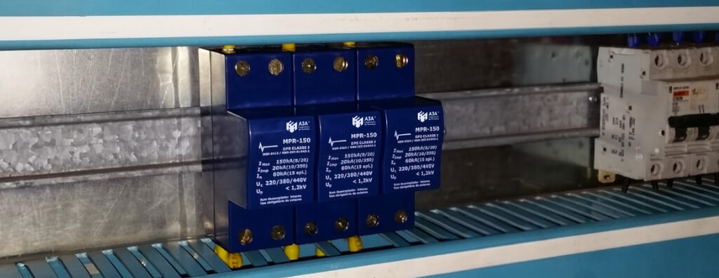
Technical guide to SPDs: operation, classes, Uc, Up, In, Iimp, installation, coordination, NBR 5410, NBR IEC 61643-11, NBR 5419-4, LPS, grounding, and inspection.
Check it out!
An SPD (Surge Protective Device) is a component intended to limit transient overvoltages and divert surge currents, reducing electrical stress on insulation and equipment. It acts mainly against short-duration phenomena associated with lightning, electromagnetic coupling, and electrical switching.
This does not mean that installation protection can be solved simply by adding SPDs to panels. Device performance depends on where it is applied, the protection modes, TN, TT, or IT system, maximum continuous operating voltage, protection level, discharge current, available short-circuit current, backup protection, connection length, and coordination with other stages.
Grounding and equipotential bonding are part of the problem. The SPD creates a path for transient current; therefore PE, neutral, PEN, BEP, BEL, equipotential-bonding conductors, and other references must be consistent with the design. Where there is an LPS or risk associated with lightning, protection must also be integrated with Surge Protection Measures — SPM — and Lightning Protection Zones.
It is also incorrect to choose a device only by markings such as 20 kA, 40 kA, 60 kA, 175 V, or 275 V. These values represent specific quantities and can only be interpreted together with the network, the likely origin of surges, equipment withstand capability, and product characteristics.
Accordingly, this guide answers the fundamental questions about SPDs but starts from an engineering premise: installation of the component is a consequence of survey, sizing criteria, and design. In existing installations, the electrical system, grounding, and equipotential bonding may first need diagnosis and upgrading so surge protection can operate as intended.
What Is an SPD and What Problem Does It Solve?
ABNT NBR IEC 61643-11 defines an SPD as a device containing at least one nonlinear component intended to limit voltage surges and divert surge currents. The central idea is simple: under normal conditions, the device interferes minimally with the circuit; when a transient overvoltage occurs, its electrical behavior changes and it offers a low-impedance path for part of the current associated with the event.
This reduces the voltage appearing between protected points. The objective is not to reduce voltage to zero or to “absorb the entire lightning strike,” but to limit stress to a level compatible with the withstand capability of the installation and equipment.
It is important to distinguish three phenomena that are often confused:
| Phenomenon | Characteristic | Typical SPD role |
| Transient overvoltage | Very fast, short-duration voltage rise caused by lightning, induction, or switching | The main phenomenon for which an SPD is applied |
| Temporary overvoltage | Voltage rise lasting significantly longer, for example because of neutral loss or faults in certain systems | Must be considered in selection because it can degrade or destroy the SPD; it is not simply “clipped” like a surge |
| Overcurrent | Current above the permissible circuit value, including overload and short circuit | Handled mainly by fuses, circuit breakers, and overcurrent protective devices |
This distinction explains why an SPD does not replace a circuit breaker. The circuit breaker protects the circuit against overcurrent conditions; the SPD is sized for overvoltage and surge-current phenomena. In some situations they work in coordination because an internal SPD failure can develop into a short circuit and require operation of backup protection.
How This Guide Connects to the Complete Surge-Protection Design
This article is the general hub of the SPD cluster. It presents the fundamental criteria, while each specialized decision is explored on its own page so different subjects are not treated as a single installation rule.
| Engineering decision | Specific content |
| Test class and functional position | Class 1, Class 2, and Class 3 SPDs |
| In, Imax, Iimp, and discharge current | 20, 40, 45, or 60 kA SPDs |
| Uc, network voltage, and TOV | 175 V or 275 V SPDs |
| 3-phase and 3-phase + neutral networks | Three-phase SPD |
| Single-phase and split/two-phase networks | Single-phase and two-phase SPD |
| Physical connection in panels | How to install an SPD in a distribution panel |
| Backup protection | SPD and circuit breaker |
| Coordination among stages | SPD coordination |
| Power, data, and signal | SPDs for data lines, CCTV, and automation |
| Photovoltaic systems | SPDs in photovoltaic systems |
| Failure, degradation, and end of life | SPD failure diagnosis |
This division is intentional: no single parameter alone determines protection. The design must relate the power supply, panels, grounding, equipotential bonding, LPS, SPM, signal lines, backup protection, and equipment withstand capability.
How Does an SPD Work?
Operation depends on the technology used. SPDs may employ varistors, spark gaps, gas-discharge tubes, suppressor diodes, or combinations of these elements. Some devices behave predominantly as voltage-limiting devices, others operate by switching, and some use combined solutions.
In voltage-limiting devices, impedance progressively decreases as voltage rises. In switching devices, the transition between high and low impedance is more abrupt. Technology selection influences characteristics such as residual voltage, impulse-current capability, follow current, aging, and application.
The dedicated article on internal SPD components explores varistors, spark gaps, GDTs, and avalanche diodes in more detail. For system design, however, the key point is that final performance depends on both the device and its connection.
When surge current flows through connection conductors, their inductance generates additional voltage. In a phenomenon with a high current rate of change, only a few centimeters of poorly routed connection can significantly increase the voltage actually appearing across the protected load. Installation geometry is therefore part of SPD performance.
In other words, an excellent SPD can perform poorly if installed with long connections, unnecessary loops, or an inadequate equipotential-bonding reference.
Class I, Class II, and Class III SPDs: What Do They Mean?
ABNT NBR IEC 61643-11:2021 structures SPD tests as Class I, Class II, and Class III. The market also commonly uses designations such as Type 1, Type 2, and Type 3. These designations are related, but the specification must always be checked against the applicable standard and manufacturer documentation rather than assuming equivalence solely from commercial terminology.
In practical terms, the test classes represent different stress conditions:
| Test class | Characteristic quantity | Typical system application |
| Class I | Impulse current Iimp, associated with high-energy stress | Boundaries where a portion of lightning current may be conducted, especially in systems associated with LPS and external zones |
| Class II | Nominal discharge current In, with 8/20 µs reference waveform | Distribution panels and protection against induced, conducted, and switching surges |
| Class III | Combination-wave generator involving 1.2/50 µs voltage and 8/20 µs current | Protection close to equipment or final coordination stages |
The important conclusion is that Class I does not simply mean “stronger SPD,” and Class III does not mean “weak SPD”. Each class represents a test condition and a functional position in the protection system.
In a complex installation, several coordinated stages may exist. An SPD at the entrance limits the energy entering the installation; intermediate devices reduce the remaining level; and a stage near a sensitive load can further reduce residual voltage. This architecture must be designed as a system rather than as a sum of independently selected products.
Which Parameters Really Matter When Selecting an SPD?
One of the main causes of incorrect specification is choosing an SPD based only on current in kA. Technical selection requires several quantities to be evaluated simultaneously.
Uc — Maximum Continuous Operating Voltage
Uc is the maximum RMS voltage that can remain continuously applied to the SPD protection mode. It must be compatible with the installation’s nominal voltage, operating tolerances, and grounding system.
Selecting Uc below the actual network condition can subject the device to continuous stress, accelerate degradation, or cause failure. On the other hand, excessively high Uc may result in a less favorable protection level depending on the product.
Up — Voltage Protection Level
Up represents the voltage protection level declared by the manufacturer. From an engineering standpoint, it must be analyzed in relation to the impulse withstand voltage of the equipment and components to be protected.
It is not enough to say “the lower Up, the better.” The value must be compatible with Uc, discharge current, SPD class, coordination, and system conditions. In addition, the voltage actually applied to the load can exceed the declared Up because of inductive voltage drops in the connections.
In — Nominal Discharge Current
In is a peak current associated with Class II tests using an 8/20 µs waveform. It is an important quantity for characterizing device capability under the established test regime.
The value should not be interpreted as the “current the SPD will always divert” or as the circuit short-circuit current.
Iimp — Impulse Current
Iimp is the quantity associated with Class I tests. It represents a higher-energy stress relevant when the SPD must conduct a portion of current related to the effects of direct lightning.
Its selection should result from analysis of the lightning-protection system and protection zones, not from a generic rule based only on installation power.
Imax — Maximum Discharge Current
Imax is a manufacturer-declared value for an 8/20 µs current and is normally greater than or equal to In. It is commonly highlighted commercially but does not replace In, Iimp, Up, Uc, or short-circuit assessment.
ISCCR and Short-Circuit Capability
The prospective short-circuit current at the installation point must be considered. ABNT NBR IEC 61643-11 addresses the SPD short-circuit-current rating associated with the specified disconnector, and NBR 5410 also requires compatibility between SPD protection and the prospective short-circuit current.
This check is especially important in main switchboards, industrial panels, and installations close to transformers, where available short-circuit current may be high.
TOV — Temporary Overvoltages
The SPD must also withstand or behave safely under temporary overvoltages (TOV). Neutral loss, faults between systems, or grounding-system conditions can expose the device to elevated voltages for periods much longer than a lightning surge.
Therefore, “a higher-current SPD” is not necessarily safer if its Uc and TOV behavior are unsuitable for the network.
How to Size an SPD: Engineering Sequence
Sizing should follow a logical sequence. Starting with a product catalog and choosing a current in kA reverses the process.
1. Characterize the Installation
First define nominal voltage, number of phases, presence of neutral, TN/TT/IT system, prospective short-circuit current, supply type, presence of a dedicated transformer, and load characteristics.
2. Identify Surge Sources
Evaluate external lines, lightning exposure, presence of LPS, outdoor equipment, switching of inductive loads, interbuilding connections, and metallic signal interfaces.
3. Define Protection Boundaries
In installations subject to NBR 5419, defining Lightning Protection Zones helps identify where surge current and voltage must be limited. In ordinary low-voltage installations, equivalent logic appears at the service entrance, intermediate panels, and near critical loads.
4. Define Protection Modes
Phase-PE, phase-neutral, neutral-PE, or other configurations depend on the grounding system and installation point. This decision affects Uc, number of poles, and behavior under faults.
5. Select Uc and Check TOV
Maximum continuous operating voltage must be compatible with the voltage that actually appears in each protection mode. Then check SPD behavior under the temporary overvoltages expected for that system.
6. Define the Required Up
The protection level must be below equipment impulse withstand capability, considering an adequate margin and the additional voltage caused by connection conductors.
7. Select In and, Where Applicable, Iimp
Current-conduction capability should reflect surge exposure and SPD position. Where a portion of lightning current may be conducted, assessment of Iimp becomes essential.
8. Check Short Circuit and Backup Protection
SPD capability and its disconnector must be compatible with the prospective current at the point. Backup fuse or circuit breaker selection should follow manufacturer documentation and installation coordination.
9. Design Coordination Between Stages
Where more than one SPD is used, verify their combined behavior and coordination instructions. It is not sufficient to install devices of “different classes” without demonstrating that the remaining energy and voltage levels are suitable.
10. Validate the Physical Installation and Document It
Finally, confirm conductor lengths, routing, equipotential-bonding bars, identification, accessibility, status indication, and documentation for inspection and maintenance.
This process turns SPD selection from product comparison into a verifiable engineering decision.
What Do 275 V, 20 kA, 40 kA, or 60 kA Mean on an SPD?
These markings appear among the most frequent searches and are a recurring source of incorrect specifications.
275 V normally appears associated with the maximum continuous operating voltage of certain SPDs for low-voltage networks, but the exact meaning must be confirmed in the data sheet. The value should not be selected simply because the installation is 220 V. The grounding system and connection mode change the voltage to which each SPD pole is subjected.
Likewise, 20 kA, 40 kA, or 60 kA may refer to In, Imax, Iimp, or another declared characteristic depending on product marking. Comparing two SPDs only by the largest kA number may mean comparing different quantities.
A correct specification starts with the question: what phenomenon must the SPD withstand, and what voltage level must it guarantee at the load? Only then can data-sheet values be compared.
When Does NBR 5410 Require Surge Protection?
NBR 5410 treats overvoltage protection as part of electrical-installation safety and performance. The edition consulted in A3A’s technical base establishes criteria for protection against transient overvoltages on power lines and also addresses metallic signal lines.
For power lines, the standard relates the need for protection to supply characteristics, installation exposure, and the consequences of an event. Where an SPD is required or specified, criteria are also defined for location, selection, coordination, and installation.
The standard dedicates a specific subsection to Surge Protective Devices, including:
- location at the service entrance or main distribution board;
- additional SPDs along the installation where necessary;
- selection by Up, Uc, In, Iimp, and short-circuit withstand capability;
- coordination among devices;
- protection against internal failure;
- compatibility with RCDs;
- status indication;
- requirements for connection conductors;
- protection of signal lines.
The article on NBR 5410 addresses the standard more broadly. For a specific design, always consult the edition current at the time of application, especially during periods of normative revision.
What Is the Relationship Among SPDs, NBR 5419, and the LPS?
A common error is to treat an SPD as synonymous with an LPS or to claim that one system replaces the other. They address different parts of the problem.
The external LPS intercepts, conducts, and disperses lightning current, reducing risks of physical damage and hazards to life. Protecting internal electrical and electronic systems requires additional measures to control conducted and induced surges.
ABNT NBR 5419-4:2026, issued in its 2026 revision, specifically addresses electrical and electronic systems within structures. It organizes protection through the concepts of Surge Protection Measures (SPM) and Lightning Protection Zones (LPZ).
The basic SPM include:
- grounding and network equipotential bonding;
- magnetic shielding and line routing;
- SPD coordination;
- isolating interfaces.
An SPD is therefore not an isolated LPS accessory. In a protection strategy against the electromagnetic effects of lightning, it forms part of an SPM architecture together with equipotential bonding, routing, shielding, and zone definition.
The content on NBR 5419-4, internal LPS, and protection of systems explains this relationship in detail.
Does the installation have an LPS, critical loads, multiple panels, or multiple metallic interfaces?
Under these conditions, choosing an SPD in isolation does not define the protection. The Surge Protection Measures (SPM) Design coordinates LPZs, classes, Uc, Up, discharge currents, grounding, equipotential bonding, power, and signal within a single architecture.
Where Should an SPD Be Installed?
Position depends on the origin of the surge, the installation architecture, and the equipment that needs protection.
Service Entrance or Main Distribution Board
For overvoltages conducted by an external line and switching surges, NBR 5410 provides for the SPD at the line entry point or main distribution board, as close as possible to that point.
This stage is essential because it limits energy before it is distributed through internal circuits.
Intermediate Distribution Boards
In extensive installations, line impedance and distance between panels may require additional stages. The objective is not to repeat the same SPD in every panel, but to create energy and voltage coordination among levels.
Close to Sensitive Equipment
Electronic equipment with low impulse withstand capability may require additional protection closer to the load. This occurs in automation, control, IT, instrumentation, electronic-security, and other critical systems.
Signal Lines
Metallic telecommunications, data, video, automation, and control lines can also carry surges into a building. In such cases, the SPD must be specific to the interface, respecting working voltage, current, frequency, bandwidth, impedance, signal category, and equipotential-bonding reference.
The article SPDs for data lines, CCTV, automation, and telecommunications covers this application in detail.
How Does the Grounding System Influence SPD Installation?
SPD connection depends directly on the grounding system. TN-S, TN-C, TN-C-S, TT, and IT establish different relationships among phases, neutral, PE, PEN, and earth, which changes the permanent voltage applied to each protection mode and the path of surge currents.
Under NBR 5410, SPD configuration varies with the system. In installations with separate neutral and protective conductors, phase-PE, phase-neutral, and neutral-PE arrangements may be used. In TN-C systems, the reference involves PEN. In TT systems, coordination between phase-neutral and neutral-PE requires special attention to system behavior under faults and temporary overvoltages.
The most important technical point is: there is no single SPD connection diagram valid for every installation.
Before defining the connection scheme, it is necessary to know:
- nominal voltage and supply configuration;
- grounding system;
- separation point between PEN, PE, and N where applicable;
- location of the main equipotential-bonding bar;
- presence of RCDs;
- prospective short-circuit current;
- presence of LPS;
- location of sensitive equipment.
The article on electrical grounding and the content on equipotential bonding explore these fundamentals further.
Will the SPD be installed in infrastructure whose grounding and equipotential bonding have not been verified?
Before final specification, PE, PEN, BEP/BEL, continuity, connections, and integration with the LPS must be understood. The Grounding Design documents this infrastructure and avoids treating the “value in ohms” as the sole performance criterion.
Why Is Connection-Conductor Length So Critical?
The residual voltage reaching equipment does not depend only on the Up declared by the SPD. During a surge, connection conductors have an additional voltage drop associated with their inductance and the high rate of current change.
Long connections and large loops can therefore significantly compromise protection performance.
The NBR 5410 edition consulted recommends that connections among phase, neutral, SPD, and PE be as short and straight as possible and uses a preferred total length on the order of 0.5 m for certain configurations. Where this is not possible, the arrangement should be reviewed to reduce the additional voltage caused by the conductors.
In practice, this means that physical panel organization is part of protection design. Selecting an SPD with excellent Up provides little benefit if it is installed far from the busbars with conductors forming loops or unnecessary routes.
The same reasoning applies to the path to the equipotential-bonding reference: the connection should be short, direct, and compatible with the grounding architecture.
Does an SPD Need a Protective Circuit Breaker or Fuse?
An SPD can fail internally and develop into a short-circuit condition. Its application must therefore consider an overcurrent protective device, internal or external, according to manufacturer design and circuit architecture.
This backup protection has two main functions:
- safely interrupt current resulting from SPD failure;
- coordinate with the device short-circuit capability and the circuit in which it is installed.
The rated current of the backup fuse or circuit breaker should not be selected using a generic rule. It must comply with manufacturer documentation, prospective short-circuit current, and selective coordination of the installation.
In critical installations, there is also a reliability decision: depending on the arrangement, operation of the protection can preserve circuit continuity while temporarily leaving the installation without surge protection, or it can disconnect the supply to maintain a safe condition. The strategy must reflect system risk and availability requirements.
The popular expression “SPD circuit breaker” can therefore be misleading. An SPD and a circuit breaker are different devices, although SPD application may require associated overcurrent protection.
SPD and RCD: Which Should Come First?
There is no universal answer such as “the SPD always comes before the RCD.” Relative position depends on the grounding system, installation configuration, and characteristics of the residual-current device.
NBR 5410 provides conditions for SPDs installed upstream or downstream of RCDs. When the SPD is installed downstream, RCD immunity to surge currents becomes relevant to avoid nuisance tripping and ensure compatibility between protections. In certain TT configurations, the SPD connection arrangement upstream of the RCD must also satisfy specific requirements.
This shows why coordination between SPD and RCD must be defined in the design rather than resolved by a fixed sequence of components in the panel.
The article on RCD, RCCB, and RCBO differences and functions explains residual-current protection and its differences from other electrical protections.
How Does Coordination Among Multiple SPDs Work?
In installations with more than one stage, SPDs must operate in a coordinated manner so that the remaining energy and voltage at each point are compatible with downstream devices and equipment withstand capability.
Coordination does not simply mean placing a higher-current SPD in the main panel and a lower-current SPD near the load. The following must be considered:
- device characteristics;
- distance and impedance between points;
- remaining energy;
- Up of each stage;
- Uc and TOV;
- connection modes;
- backup protection;
- manufacturer coordination instructions.
NBR 5410 itself requires manufacturers to provide instructions for SPD coordination. ABNT NBR 5419-4:2026 addresses the subject in greater depth and dedicates its normative Annex C to selection and installation of a coordinated SPD system.
The article SPD Coordination is the dedicated page for this topic.
SPDs for Data Lines, CCTV, Automation, and Telecommunications
Surge protection does not end at the electrical power supply. A metallic signal line entering or leaving a building can introduce potential differences directly into connected equipment.
NBR 5410 addresses protection of external signal lines, and the technical base also includes IEC 61643-21, specifically for protective devices connected to telecommunications and signaling networks.
In this type of application, besides the ability to conduct surges, signal operation must be preserved. Selection may involve:
- maximum operating voltage;
- load current;
- frequency or bandwidth;
- insertion loss;
- interface impedance;
- connection topology;
- equipotential-bonding reference;
- protocol category and type.
An SPD suitable for the electrical power supply cannot be used indiscriminately on Ethernet, video, RS-485, analog lines, coaxial links, or control interfaces.
In critical systems, protection must be coordinated between power and signal. Equipment connected simultaneously to the electrical network and an external metallic line can be damaged even when only one interface is protected.
SPDs in Photovoltaic Systems and Direct Current
Photovoltaic systems have characteristics that prevent simply transferring an AC SPD to the DC side.
A3A’s technical base includes ABNT NBR IEC 61643-31, which addresses SPDs for specific direct-current applications, and ABNT NBR IEC 61643-32, which covers principles for selecting and applying SPDs on the DC side of photovoltaic installations.
Selection must consider maximum array voltage, photovoltaic-source behavior, polarity, short-circuit current, disconnection method, coordination between DC and AC sides, and cable exposure to lightning effects.
The article Surge Protection in Photovoltaic Systems explores this application further.
How Should SPDs Be Inspected and Maintained Throughout Their Service Life?
The fact that an SPD is installed does not mean it remains operational or suitable for the current installation configuration.
Varistors and other components can undergo cumulative degradation. High-energy events, TOV, temperature, aging, and repeated operations can alter performance. Many SPDs include status indicators; models intended for critical installations may provide remote contacts for supervision.
An inspection should verify at least:
- SPD status indication;
- evidence of heating, carbonization, or deformation;
- tightness and condition of connections;
- associated backup protection;
- compliance of the installed model with the design;
- subsequent changes to the panel or power supply;
- integrity of PE, equipotential bonding, and grounding;
- coordination with other stages;
- device documentation and traceability.
ABNT NBR 5419-4:2026 expressly addresses inspection, maintenance, and documentation of SPM, reinforcing that surge protection is a system that must remain verifiable during operation.
Is there a history of degraded SPDs, damaged equipment, or subsequent modifications to panels?
In that case, replacing the component without investigating the cause may simply repeat the failure. SPD and SPM Inspection, Diagnosis, and Upgrading verifies the device, backup protection, grounding, equipotential bonding, coordination, and actual installation condition before correction.
In industrial and critical installations, SPD remote contacts can be integrated with automation or supervisory systems so loss of protection is identified quickly.
What Are the Most Common Errors in SPD Designs?
Most problems do not result from a complete absence of SPDs, but from protection that appears to be present while remaining technically inconsistent.
The most frequent errors include:
- choosing an SPD only by the highest kA value, without identifying whether the number represents In, Imax, or Iimp;
- ignoring Uc and behavior under temporary overvoltages;
- selecting Up without considering equipment withstand capability and additional voltage in the connections;
- installing the SPD with long conductors, bends, and loops;
- disregarding the TN, TT, or IT system in the connection;
- installing only one stage in extensive installations or those with highly sensitive loads;
- adding multiple SPDs without checking coordination among them;
- ignoring prospective short-circuit current and backup protection;
- treating grounding only as a “resistance value” and ignoring equipotential bonding and geometry;
- protecting the power supply while leaving metallic signal lines exposed;
- using an AC device on a DC circuit without checking the applicable standard and application;
- failing to coordinate SPD, RCD, and overcurrent protection;
- assuming an external LPS eliminates the need for internal SPM;
- failing to record model, parameters, location, and coordination criteria in technical documentation;
- failing to provide for inspection or replacement after failure or degradation.
These errors demonstrate why surge protection must be treated as part of the electrical design and technical risk management, not as isolated purchase of a component.
When Does SPD Assessment Require Specialized Engineering?
In simple installations, application may be resolved using standards and manufacturer documentation by a qualified professional. In more critical systems, however, the analysis tends to involve multiple disciplines and interfaces.
An engineering assessment is recommended where there is:
- a recurring history of equipment damage;
- an existing LPS or an LPS design under development;
- data centers, technical rooms, or critical IT infrastructure;
- industrial automation, instrumentation, or control systems;
- CCTV, access control, and electronic security distributed across outdoor areas;
- multiple panels and long internal distances;
- a dedicated substation or high available short-circuit current;
- TT or IT networks with specific requirements;
- photovoltaic systems;
- absence of diagrams or As-Built documentation;
- renovations, expansions, or changes to the grounding system;
- need for standards compliance or commissioning.
In these situations, an electrical-installation inspection can identify the actual condition before corrective measures are defined. Where circuits, panels, or protection architecture will be changed, the low-voltage electrical design should consolidate assumptions, diagrams, specifications, and coordination criteria.
If the source of risk involves lightning, the analysis must be coordinated with the LPS design and the grounding design. In installations with high available current, the short-circuit, selectivity, and protection-coordination study provides the data needed to validate backup protection and component capability.
Completion of the intervention should include verification and documentation. In new or renovated installations, commissioning and acceptance of electrical installations makes it possible to confirm that installed devices correspond to the design and that connections, identification, and final documentation are compatible with the specified system.
The correct approach, therefore, is not merely to ask “which SPD should I buy?”, but to define what protection level the system requires, against which phenomena, at which boundaries, and with which coordination, inspection, and maintenance criteria.
Technical references
[1] BRAZILIAN ASSOCIATION OF TECHNICAL STANDARDS. ABNT NBR 5410:2004 — Low-voltage electrical installations. Corrected version 2008. Consult the current edition in the ABNT Catalog.
[2] BRAZILIAN ASSOCIATION OF TECHNICAL STANDARDS. ABNT NBR IEC 61643-11:2021 — Low-voltage surge protective devices — Part 11: Requirements and test methods. Corrected version 2022. Consult the current edition in the ABNT Catalog.
[3] BRAZILIAN ASSOCIATION OF TECHNICAL STANDARDS. ABNT NBR 5419-4:2026 — Protection against lightning — Part 4: Electrical and electronic systems within structures. Consult the current series in the ABNT Catalog.
[4] INTERNATIONAL ELECTROTECHNICAL COMMISSION. IEC 61643-21 — Low-voltage surge protective devices connected to telecommunications and signalling networks. Consult the official catalog at the IEC.
Frequently asked questions
SPD stands for Surge Protective Device. It is a component that limits transient overvoltages and diverts surge currents to reduce electrical stress on the installation and equipment.
An SPD protects installations and equipment against transient overvoltages caused mainly by lightning, electromagnetic induction, and electrical switching. It does not replace circuit breakers, RCDs, grounding, or an LPS.
When a transient overvoltage occurs, nonlinear components inside the SPD change their electrical behavior, limiting voltage between protected points and conducting part of the surge current through the path defined by the design.
The classes correspond to different test conditions. Class I involves impulse current Iimp and higher-energy applications; Class II uses In with an 8/20 µs waveform; Class III uses a combination wave and normally appears in stages close to loads. Selection must consider the complete system.
On many products, 275 V is associated with maximum continuous operating voltage Uc, but the quantity must be confirmed in the data sheet. Selection depends on network voltage, grounding system, and connection mode.
The higher kA value alone does not define the better SPD. It is necessary to know whether the number represents In, Imax, Iimp, or another quantity and also verify Uc, Up, TOV, short circuit, class, installation point, and coordination.
Installation depends on the TN, TT, or IT system, panel position, presence of RCDs, backup protection, and equipotential-bonding reference. Connections should be short and straight, and the arrangement must follow the current standard and manufacturer documentation.
Backup overcurrent protection may be necessary because an internal SPD failure can create a short circuit. The device and its rated current must follow manufacturer documentation and the prospective short-circuit current at the installation point.
There is no universal rule. Position depends on the grounding system and RCD characteristics. NBR 5410 provides conditions for SPDs upstream or downstream and requires compatibility between protections.
SPD performance depends on integration with the grounding system and equipotential bonding. Connection to PE, PEN, neutral, or the equipotential-bonding bar varies according to the installation architecture.
The external LPS primarily addresses interception and conduction of lightning current. The SPD forms part of measures protecting electrical and electronic systems against conducted and induced surges. The two systems must be coordinated.
Status indicators, signs of heating or damage, and manufacturer documentation guide inspection. In critical installations, remote contacts can indicate loss of protection. Changes to the installation may also require reassessment even if the SPD appears intact.
Additional technical materials
Related solutions
- Surge Protection Measures
- Surge Protective Devices (SPD)
- Grounding and Equipotential Bonding
- Low-Voltage Electrical Infrastructure
Related engineering services
- Surge Protection Measures (SPM) Design
- SPD and SPM Inspection, Diagnosis, and Upgrading
- Electrical Installation Inspection
- Low-Voltage Electrical Design
- Grounding Design
- LPS Design
- Short-Circuit, Selectivity, and Protection-Coordination Study
- Commissioning and Acceptance of Electrical Installations
Related technical content
- SPD Coordination
- How Internal SPD Components Operate
- SPDs for Data Lines, CCTV, Automation, and Telecommunications
- Surge Protection in Photovoltaic Systems
- NBR 5419-4: Internal LPS, SPDs, and System Protection
- NBR 5410: LV Electrical Installations, Grounding, SPDs, and Compliance
- Electrical Grounding
- Equipotential Bonding or Potential Equalization
