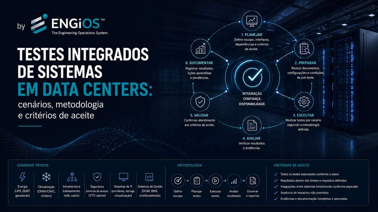
Understand Data Center IST: scenarios, failures, transitions, readiness, safety, evidence, acceptance criteria, retesting and commissioning governance.
Check it out!
Integrated Systems Testing in Data Centers verifies whether critical infrastructure responds in a coordinated manner when there is a state change, planned maintenance, failure, degraded condition, or emergency. The objective is not merely to confirm that each piece of equipment works in isolation, but to demonstrate that power, cooling, automation, telecommunications, security, fire protection, controls, and operations jointly preserve the critical function within defined limits.
This distinction is essential. A UPS may have passed its functional test; a generator set may have completed startup; a chiller may have reached rated capacity; the BMS may have received the expected points. Even so, the infrastructure may fail when these systems need to act in sequence. It is precisely at this boundary between systems that command delays, inconsistent interlocks, ambiguous alarms, hidden dependencies, communication failures, incorrect priorities, and difficulties returning to the normal state emerge.
In this context, IST means Integrated Systems Testing or Integrated Systems Test: scenario-driven integrated verification that evaluates interfaces, degraded states, failures, recovery, and operational response. This article focuses on how to structure, execute, record, and accept this type of testing in Data Centers, distinguishing it from earlier levels of the commissioning process.
What is Integrated Systems Testing in Data Centers?
Integrated Systems Testing is a scenario-driven verification. It induces or simulates predefined events and observes whether the systems involved respond in accordance with the owner’s requirements, design basis, operating sequences, control logic, approved procedures, and performance criteria. In the complete cycle, this stage follows earlier verifications such as FAT, SAT, pre-commissioning, and functional testing; the overview of levels and gates is presented in the article on Data Center Commissioning, while the distinction among FAT, SAT, and integrated testing is addressed separately.
Instead of asking only “did the equipment work?”, IST seeks to answer:
- was the event detected correctly?
- did the protections operate in the expected order?
- did the critical load remain supported?
- did the alternate system enter operation within the required time?
- was the remaining capacity sufficient?
- did thermal conditions remain within limits?
- were alarms received, prioritized, and understood?
- did the team identify the actual state of the facility?
- did the system remain stable for the defined period?
- did the return to normal occur safely?
- was redundancy restored and confirmed?
- does the evidence demonstrate the result?
A utility-power-loss scenario, for example, may involve condition detection, protection operation, support by UPS systems and batteries, generator-set startup, load transfer, prioritization of auxiliary systems, continuity of cooling, supervisory-system updates, alarm generation, team response, and subsequent return to the normal state.
The result cannot be reduced to “there was no shutdown.” The test needs to demonstrate that the complete response was consistent with the requirements and that no hidden conditions emerged that could compromise future operations.
IST, SAT, functional testing, and performance testing
Terminology should be defined in the commissioning plan and contract because different organizations use their own nomenclature. The practical difference lies in the object of verification: SAT addresses field acceptance of equipment or a system; functional testing demonstrates functions within a discipline; IST verifies interfaces and joint response; and performance testing demonstrates measurable parameters under defined conditions.
| Type | Primary focus | Data Center example |
|---|---|---|
| SAT — Site Acceptance Test | Field acceptance after installation | Configuration, energization, communication, and specific performance of a UPS or switchboard |
| Functional test | Functions, sequences, and interlocks of a system | Transfer to batteries, bypass, alarms, and load sharing of the UPS system |
| IST — Integrated Systems Testing | Interaction among systems in a common scenario | Source loss with coordinated response of UPS, generators, distribution, cooling, BMS, EPMS, and operations |
| Performance test | Guaranteed parameters under defined conditions | Capacity, autonomy, timings, environmental conditions, or performance under load |
IST may incorporate performance measurements, but its distinguishing feature is verification of the interface chain. ABNT NBR IEC 62337 reinforces that starting conditions, instrumentation, measurement methods, tolerances, duration, evaluation, and reporting should be defined in advance when performance is to be demonstrated.
Technical and standards basis
ABNT NBR ISO/IEC 22237-1 establishes that operations, management, processes, and indicators should be considered from the design stage. The standard also states that processes, roles, and responsibilities should be defined before operations begin and that the operations team should be instructed on the infrastructure and trained during acceptance testing.
The same standard requires acceptance verification and commissioning before the Data Center is handed over for operation. Its concepts of availability, reliability, and resilience reinforce that a facility should not be evaluated solely by the presence of redundant components, but by its ability to perform the intended function and withstand failures.
ABNT NBR IEC 62337, although originating in electrical systems, instrumentation, and industrial-process control, provides principles directly applicable to commissioning governance: defined phases and milestones, test planning, documentation, responsibilities, punch lists, detailed procedures, operating records, readiness conditions, formal evaluation, and owner acceptance.
Uptime Institute’s Tier Standard: Operational Sustainability includes operational integrated-systems testing as relevant pre-operational behavior for higher-criticality facilities. The same standard emphasizes that commissioning, training, procedures, maintenance, and management are necessary for the infrastructure to realize the performance potential of its topology.
Discipline-specific standards remain applicable. ABNT NBR 17207 establishes environmental criteria for ICT environments and Data Centers; ABNT ISO/IEC TS 22237-5 addresses availability and multiple paths in telecommunications infrastructure; and ABNT NBR 17240 establishes specific requirements for fire detection and alarm systems. IST should integrate interfaces without replacing statutory tests, regulatory acceptance, or discipline-specific technical responsibilities.
What is the objective of IST?
The objective of IST should be defined from project requirements. The first dimension is functional: demonstrate that the critical load remains supported, that protections and interlocks operate correctly, and that systems coordinate their responses without creating conflicting states.
The second dimension concerns resilience and operations. The test needs to demonstrate remaining capacity in degraded states, maintenance of environmental conditions, stability during the observation period, and the ability to recover the facility and restore redundancy. BMS, EPMS, DCIM, and other platforms should record events coherently so the team understands the actual state of the Data Center.
Finally, the result needs to be traceable: data, timings, trends, alarms, interventions, and decisions should allow the scenario to be reconstructed and support acceptance. The objective is not to prove that “everything works at the same time,” but to confirm scenarios selected based on relevant risks, requirements, architecture, and failure modes.
IST is not a staged demonstration
The test needs to produce evidence of the coordinated response of the systems, including intermediate states, limitations, and degraded conditions.
Structure IST scenarios, evidence, and acceptance criteria with independent technical governance →
IST should be driven by requirements and risks
Generic scripts produce generic tests. The scenario matrix needs to derive from the documents that define the project, including:
- OPR, URS, or owner requirements;
- Basis of Design;
- single-line and functional diagrams;
- operating sequences;
- cause-and-effect matrices;
- selectivity, short-circuit, and coordination studies;
- load lists and priorities;
- calculation reports;
- failure-mode analysis;
- business risk analysis;
- availability requirements;
- contracts and performance guarantees;
- manufacturer manuals;
- MOPs, SOPs, and EOPs;
- legal and authority requirements.
The analysis should identify which events may compromise the critical function, which interfaces participate in the response, and which evidence demonstrates the result.
A traceability matrix makes it possible to relate:
requirement → risk → scenario → stimulus → expected response → measured variable → acceptance criterion → evidence → approval owner.
This structure reduces gaps and prevents the test from being defined only on the basis of participants’ informal experience.
Readiness is a gate, not a perception
IST should begin only when requirements, configuration, individual systems, instruments, team, and restoration criteria have been formally verified.
Structure technical governance with Owner’s Engineering for Data Centers
Prerequisites for starting Integrated Systems Testing
IST should not be used to discover basic installation deficiencies. Before authorizing scenarios, a formal readiness review should be performed.
Updated requirements and documentation
Documents should represent the actual facility. Outdated diagrams, field-modified logic, inconsistent labels, and unrevised sequences compromise test safety and validity.
The minimum basis includes:
- approved OPR, URS, and Basis of Design;
- available as-built diagrams;
- updated operating sequences;
- automation point list;
- interlock and cause-and-effect matrices;
- recorded system configurations;
- supplier manuals and documentation;
- operating and emergency procedures;
- scenario matrix and acceptance criteria.
Individual systems completed
The components and systems involved should have completed the earlier tests defined in the plan. Depending on the methodology, this includes FAT, receiving, inspection, pre-functional checks, startup, SAT, and functional tests.
Starting IST while basic systems are still unstable produces inconclusive results and increases the risk of damage.
Classified open items
The punch list should be reviewed by criticality. Open items that may alter scenario response, prevent observability, compromise safety, or require improvised intervention should be closed before testing.
Temporarily accepted open items need to be documented and accompanied by impact analysis and approval by the designated authority.
Controlled configuration
The initial state of the systems should be known and recorded. This includes:
- equipment in service and standby;
- valve alignment;
- breaker and switch positions;
- automatic, manual, or maintenance modes;
- setpoints;
- inhibited alarms;
- active bypasses;
- temporary logic;
- software and firmware versions;
- existing unavailabilities.
Without configuration control, the result cannot be reproduced or compared.
Instrumentation and observability available
The systems need to record what occurred. BMS, EPMS, DCIM, and specific platforms should be operational, with trends configured, histories available, and clocks synchronized.
When permanent instruments are insufficient, suitable and calibrated temporary instruments should be used.
Team and responsibilities defined
The test should have a clear command structure. All participants need to know who:
- authorizes the start;
- conducts the script;
- performs switching and actions;
- monitors each system;
- records the data;
- may stop the test;
- approves return to the normal state;
- classifies issues;
- accepts the result.
Governance and authority during IST
Integrated testing involves multiple organizations: owner, operations, commissioning agent, designers, contractors, integrators, suppliers, IT team, security, fire protection, and system specialists.
A RACI matrix should define responsibilities by activity and scenario. In general terms:
- the owner defines requirements and accepts the result;
- the commissioning agent coordinates independence, traceability, and the verification process;
- the operations validates conditions, executes or supervises switching, and confirms the ability to sustain the asset;
- the suppliers support testing of their equipment and warranty limits;
- the designers clarify design intent, sequences, and criteria;
- the integrators support logic, communications, and supervision;
- the occupational safety controls risks and permits;
- the IT confirms impact and continuity of the technology load.
Stop-test authority should be explicit. Any designated participant should be able to stop the test when there is risk to people, equipment, critical load, or facility integrity.
How to structure a scenario matrix
The IST matrix should organize events in a clear and traceable manner. Each row may contain:
- scenario code;
- related requirement;
- initiating system;
- simulated event or condition;
- participating systems;
- initial configuration;
- preconditions;
- applied stimulus;
- expected response;
- maximum times or acceptable ranges;
- monitored variables;
- abort criteria;
- restoration procedure;
- required evidence;
- owners;
- result and issue number, when applicable.
The matrix should be reviewed by the disciplines involved. An apparently electrical scenario may require participation from mechanical, automation, telecommunications, and operations teams.
Scenario families for Data Centers
Normal operation
Verifies stable conditions and planned transitions without failure, such as:
- scheduled alternation of redundant equipment;
- rotation of lead and standby units;
- capacity modulation;
- controlled transfer of paths;
- authorized setpoint changes;
- return to the initial state;
- behavior of informational alarms.
These scenarios confirm whether the facility can execute required routines without creating unexpected degradation.
Planned maintenance
Evaluates controlled removal of a component or path for maintenance. It should verify:
- remaining capacity;
- safe isolation;
- load continuity;
- thermal stability;
- expected alarms;
- supervisory-system updates;
- exposure to an additional failure;
- return and restoration of redundancy.
The article on concurrent maintainability in Data Centers explores the specific criteria for this condition.
Source or component failure
May include loss of:
- utility supply;
- transformer;
- switchboard or busbar;
- UPS module;
- battery bank or string;
- generator set;
- pump;
- chiller;
- cooling tower;
- CRAH or CRAC;
- controller;
- communications network;
- critical sensor.
The scenario should respect manufacturer limitations and avoid unplanned destructive methods. When the real failure cannot be safely applied, an authorized simulation may be used provided its representativeness is demonstrated.
Degraded state
The test should observe facility behavior after loss of redundancy, even if the load remains supported.
It is necessary to verify:
- available capacity;
- thermal and electrical margins;
- alarms and priorities;
- operating restrictions;
- maximum permitted time in this condition;
- required team actions;
- risk of additional failure;
- escalation criteria.
Communications and automation failures
The physical infrastructure may remain available while supervision loses visibility or controllers stop coordinating sequences.
Relevant scenarios include:
- loss of the BMS network;
- server or operator-station failure;
- loss of communication with PLC, UPS, generator, or meter;
- mismatch between local and supervisory state;
- frozen value;
- sensor failure;
- loss of time synchronization;
- historian unavailability;
- operation in local or degraded mode.
The test should confirm that monitoring failure does not trigger improper commands and that the team can identify the actual condition.
Fire and security
Fire interfaces may involve detection, alarm, suppression, shutdown or continued operation of equipment, access control, door release, elevators, cooling, dampers, power, and communications.
Each scenario needs to comply with ABNT NBR 17240, the approved design, authority requirements, and the responsibilities of qualified professionals.
IST does not replace commissioning of the fire system itself. It verifies the interfaces required for the Data Center’s integrated response.
Environmental conditions
Scenarios may assess loss of a cooling unit, pump failure, circuit unavailability, flow change, loss of containment, setpoint variation, or sensor failure.
Measurements should observe, as applicable:
- ICT equipment inlet temperature;
- humidity and dew point;
- air or liquid flow;
- differential pressure;
- water temperature;
- response time;
- stability after the event;
- hotspots and recirculation.
NBR 17207 establishes that environmental parameters should be maintained under design conditions and that analysis should consider thermal load, variations, redundancy, and reliability.
Recovery and return to normal state
The scenario does not end when the load remains energized. It is necessary to test:
- return of the primary source;
- resynchronization and transfer;
- generator shutdown and cooldown;
- battery recharge;
- return of standby equipment;
- restoration of valves and paths;
- normalization of setpoints;
- alarm clearing;
- confirmation of redundancy;
- subsequent stability;
- update of operational records.
Many failures appear during restoration rather than during the initial event.
The scenario ends only after redundancy is restored
Source return, control normalization, alarm clearing, and stability confirmation are part of the test and acceptance criteria.
Connect IST results to operational MOP, SOP, and EOP procedures →
How to write an integrated test script
The script needs to be executable, auditable, and safe. It should contain at least the following elements.
Identification and objective
Indicate code, title, participating systems, associated requirement, assessed risk, and the result to be demonstrated.
References
List diagrams, sequences, manuals, studies, procedures, the cause-and-effect matrix, and standards documents used.
Initial configuration
Describe the state required to start the scenario, including active equipment, standby equipment, positions, setpoints, loads, control modes, alarms, and unavailabilities.
Preconditions and gate
Define conditions that need to be confirmed before starting:
- systems available;
- accepted open items;
- instruments installed;
- communications tested;
- team present;
- valid permits;
- stable environmental conditions;
- restoration plan verified.
Execution steps
Each step should indicate:
- action;
- executor;
- expected result;
- observation point;
- required record;
- advance criterion.
The wording needs to avoid vague commands such as “simulate failure.” The authorized method and exact actuation point should be specified.
Abort criteria
Objective limits should be defined for stopping the test, such as:
- unplanned loss of critical load;
- temperature above the established limit;
- equipment or path overload;
- unexpected protection operation;
- loss of communication essential to safety;
- leakage, smoke, abnormal noise, or vibration;
- inability to perform restoration;
- condition not understood by the team.
Restoration plan
The script should establish how to return to a safe condition, including in the event of a test failure. The plan should consider manual actions, responsible parties, communication, support equipment, and conditions for restart.
Acceptance criteria
Each expected response should have a measurable or verifiable condition. “Normal operation” is not a sufficient criterion.
Safety during execution
IST may involve electrical energy, fuels, batteries, pressurized systems, rotating equipment, high temperatures, water, suppression agents, alarms, and temporary changes in redundancy.
Planning should integrate:
- task risk analysis;
- work permits;
- lockout/tagout, when applicable;
- manufacturer recommendations;
- responsibility boundaries;
- personal and collective protection;
- emergency communication;
- presence of specialists;
- access control;
- temporary-change management;
- contingency plan;
- stop-test authority.
No commissioning objective justifies an unsafe intervention. When the real failure cannot be induced in a controlled manner, a technically substantiated alternative method should be used.
Instrumentation, synchronization, and evidence
The quality of the result depends on measurement quality. IST needs to capture not only the final state but also the temporal sequence of the event.
Possible instruments
- power-quality analyzers;
- electrical data loggers;
- oscillography and protection records;
- thermography;
- temporary temperature and humidity sensors;
- flow and pressure meters;
- resistive or reactive load banks;
- speed and vibration recorders;
- PLC and controller logs;
- BMS and EPMS trends;
- DCIM events;
- fire and security system records;
- network captures;
- synchronized video of operations.
Time synchronization
Divergent clocks prevent event reconstruction. Before testing, synchronization among instruments, BMS, EPMS, DCIM, PLCs, security systems, cameras, and manual records should be verified.
When automatic synchronization is unavailable, a correlation method should be established.
Sampling rate
The recording frequency should match the speed of the phenomenon. An interval suitable for thermal trends may be insufficient to capture electrical transfers, protection operations, or transients.
Minimum evidence
For each scenario, collect:
- approved script;
- participant list;
- initial configuration;
- briefing records;
- raw data;
- trends and events;
- relevant photographs or videos;
- chronological notes;
- observed deviations;
- open issues;
- retest result;
- final approval.
Step-by-step execution
1. Readiness meeting
The team reviews objective, risks, configuration, responsibilities, abort criteria, and restoration. Any critical uncertainty prevents the start.
2. Baseline recording
Before the stimulus, states, loads, temperatures, pressures, alarms, and equipment in service are recorded. This baseline makes it possible to compare subsequent behavior.
3. Application of stimulus
The event is induced or simulated according to the approved method. Execution should strictly follow the script.
4. Observation of response
Each discipline monitors its variables and confirms expected events. Unplanned interventions should be recorded.
5. Hold at representative condition
Where applicable, the degraded state should be maintained long enough to demonstrate stability, capacity, and environmental conditions.
6. Restoration
The team executes the return sequence and confirms restoration of systems, alarms, and redundancies.
7. Post-test verification
Final states, abnormal conditions, latent alarms, temporary changes, tools, and lockouts are reviewed.
8. Immediate debrief
Participants record observations while the event is still fresh. Preliminary results, deviations, and actions are consolidated.
IST acceptance criteria
Criteria need to be established before execution and linked to project requirements. Acceptance should not depend solely on load continuity: function, timing, capacity, environmental conditions, observability, operational response, and complete restoration need to be demonstrated.
| Dimension | What must be demonstrated |
|---|---|
| Functional | Correct sequences, protections, and interlocks; critical loads preserved; alternate systems available; coherent automation and no conflicting commands. |
| Timing | Detection, transfer, startup, stabilization, autonomy, thermal-response, recovery, and alarm-generation times within defined limits. |
| Capacity and environment | Loads within equipment limits, adequate remaining margin, sufficient thermal capacity, and environmental conditions consistent with requirements. |
| Observability | Events recorded, correct and prioritized alarms, coherent local and remote states, sufficient data for reconstruction, and adequate time synchronization. |
| Operational | Team able to recognize the condition, apply procedures, escalate issues, and execute actions without improvisation. |
| Restoration | Normal state restored, redundancy confirmed, alarms cleared or addressed, setpoints restored, temporary changes removed, and stability verified after return. |
A scenario may keep the load energized and still fail if it presents overload, loss of monitoring, inadequate thermal response, incorrect alarms, unplanned manual intervention, or inability to restore safely.
Load continuity is not the only approval criterion
Acceptance needs to consider function, timing, capacity, environment, observability, operational response, and complete restoration.
Issue, failure, and retest management
Every deviation between expected and observed results should generate a record. The issue should contain:
- scenario and step identification;
- objective description;
- time and observed condition;
- impact;
- evidence;
- analysis owner;
- probable cause;
- corrective action;
- need for document change;
- closure criterion;
- required retest.
Failure history should not be erased after correction. Traceability demonstrates how the facility evolved and helps prevent similar problems from recurring.
Classification by criticality
A practical classification may consider:
- critical: compromises safety, critical load, or scenario validity;
- high: prevents an availability or restoration requirement from being met;
- medium: reduces performance, observability, or operational capability;
- low: documentary or workmanship deviation without immediate functional impact.
The classification should be defined by the project.
Retest
The retest should verify the correction without losing the system-level view. In some cases, repeating only the affected step is sufficient. In others, the change may affect interfaces and require repetition of the complete scenario or a family of scenarios.
Verification by discipline
Electrical system
Scenarios may involve sources, transformers, switchboards, UPS systems, batteries, generators, ATS, STS, PDUs, A/B distribution, protection, and EPMS.
The following should be observed:
- load continuity;
- selectivity and protection operation;
- transfer times;
- voltage and frequency stability;
- load sharing;
- autonomy;
- startup and paralleling;
- load priority;
- bypass behavior;
- restoration after return.
Cooling
The test should consider the coordinated response of chillers, pumps, towers, CRAHs, CRACs, CDUs, valves, controls, containment, and sensors.
The following should be verified:
- remaining capacity;
- startup and shutdown sequence;
- pressure and flow stability;
- maintenance of temperature and humidity;
- response to loss of a unit or circuit;
- automation behavior;
- recovery time;
- conditions during emergency power operation.
Automation and supervision
BMS, EPMS, PLCs, and DCIM should record and display the correct condition. The test needs to verify alarms, priorities, timestamps, states, commands, permissives, trends, and communication failures.
Telecommunications and network
ABNT ISO/IEC TS 22237-5 establishes multiple physical paths for higher availability classes and highlights the need for redundancy in active equipment. IST should evaluate paths, reconvergence, link loss, control communications, and impact on supervisory systems.
Fire and security
Interfaces should be verified according to the design and applicable standards. This may include detection, alarm, access release, damper operation, cooling, authorized shutdowns, suppression, and communications.
Integrated testing in existing Data Centers
In operating facilities, risk is higher because the real load is present. The scope should be adapted based on risk analysis and criticality.
Approaches may include:
- document review and walkdown;
- authorized signal simulation;
- testing during maintenance windows;
- use of temporary loads;
- testing by subsystem or zone;
- execution in a redundant environment;
- digital twin or complementary simulation;
- verification of selected scenarios;
- recommissioning after changes.
The article on recommissioning after expansion or modernization details the need to redefine the baseline after changes.
No limitation should be hidden. The report needs to indicate which scenarios were tested, simulated, inferred, or not executed.
Integrated testing deliverables
A complete program may produce:
- IST plan;
- requirements and scenario matrix;
- interface matrix;
- test risk analysis;
- readiness review;
- approved scripts;
- briefing records;
- raw data and trends;
- scenario reports;
- issue list;
- retest reports;
- final compliance matrix;
- executive report;
- record of limitations and residual risks;
- procedure updates;
- formal owner acceptance.
The executive report should translate technical results into decision conditions: approved, approved with restrictions, retest required, or not approved.
Common mistakes
Treating IST as a demonstration
A rehearsed presentation without prior criteria or data recording does not demonstrate performance.
Starting before readiness
Integrated testing should not compensate for installation, logic, or documentation deficiencies.
Testing only power
Electrical continuity does not guarantee cooling, control, communications, security, or recovery.
Using generic scripts
The scenario needs to reflect the project’s actual architecture and requirements.
Ignoring the degraded state
Loss of redundancy may be operationally critical even without an immediate shutdown.
Failing to test restoration
The return to normal may introduce new failures and needs to be part of the scenario.
Recording only the final result
The temporal sequence and intermediate conditions are essential for evaluation.
Changing logic during the test without control
Any modification should be recorded, analyzed, and subjected to retesting.
Accepting unplanned manual intervention
Improvised corrective action during the scenario may mask a design or automation failure.
Excluding operations
The team that will receive the asset needs to participate in preparation, execution, debriefing, and procedure updates.
Executive checklist
Before IST, confirm:
- are the requirements approved and traceable?
- have the individual systems completed the planned tests?
- do diagrams and sequences reflect field conditions?
- has the punch list been classified?
- are there no open items that invalidate the scenario?
- is the initial configuration recorded?
- are instruments calibrated?
- are clocks synchronized?
- do BMS, EPMS, and DCIM record trends and events?
- are acceptance criteria defined?
- are abort criteria clear?
- has the restoration plan been reviewed?
- are responsible parties present?
- are start and stop-test authorities defined?
- have manufacturers approved the failure or simulation method?
- have safety risks been controlled?
During the test, confirm:
- was each action executed according to the script?
- were responses observed by all disciplines?
- were timings recorded?
- were unplanned interventions documented?
- did the degraded state remain stable?
- were critical load and environmental conditions preserved?
- were alarms correct and understandable?
- did the team recognize the condition?
After the test, confirm:
- was the normal state restored?
- was redundancy restored?
- were bypasses, inhibitions, and temporary logic removed?
- were the data preserved?
- were issues opened?
- was the debriefing performed?
- was the required retest defined?
- did the owner record acceptance?
Conclusion
Integrated Systems Testing in Data Centers is the stage at which infrastructure stops being evaluated as a collection of independent equipment and begins to be verified as a critical system. Its value lies in revealing interface failures, hidden dependencies, inadequate timings, inconsistent alarms, capacity limitations, and recovery difficulties before these conditions cause real downtime.
A technically robust IST requires traceable requirements, previously tested systems, controlled configuration, risk-driven scenarios, detailed scripts, adequate instrumentation, time synchronization, abort criteria, restoration procedures, issue management, and formal acceptance.
A3A Engenharia works in the planning, review, supervision, and documentation of integrated testing in Data Centers, connecting requirements, design, execution, operations, and acceptance criteria to produce independent evidence of critical-infrastructure readiness.
Technical references
[3] UPTIME INSTITUTE. Data Center Site Infrastructure Tier Standard: Operational Sustainability.
[4] UPTIME INSTITUTE. Data Center Site Infrastructure Tier Standard: Topology.
[5] ISO; IEC. ISO/IEC TS 22237-7 — Information technology — Data centre facilities and infrastructures — Part 7: Management and operational information.
[6] ABNT. ABNT NBR 17207:2025 — Ventilation and air-conditioning systems in information technology, communications, and Data Center environments.
[7] ABNT. ABNT ISO/IEC TS 22237-5:2024 — Information technology — Data centre facilities and infrastructures — Part 5: Telecommunications cabling infrastructure.
[8] ABNT. ABNT NBR 17240 — Fire detection and alarm systems — Design, installation, commissioning, and maintenance of fire detection and alarm systems — Requirements.
Frequently asked questions
It is a scenario-driven test that verifies whether different systems and interfaces respond in a coordinated manner to normal, degraded, failure, maintenance, or emergency conditions while preserving the critical function and producing traceable evidence.
No. Functional testing verifies a system or discipline. IST evaluates the interaction among power, cooling, automation, telecommunications, security, fire protection, and operations during a common event.
In many commissioning programs, yes. However, L1–L5 numbering is not universal and should be defined in the plan and contract. The technical content of the test is more important than the label.
Updated requirements and documents, tested individual systems, closed critical open items, controlled configuration, calibrated instruments, operational supervisory systems, defined team, and approved acceptance criteria and restoration plan.
Not in all cases. When the real failure cannot be safely induced or would create disproportionate risk, an authorized simulation may be used provided its representativeness and limitations are demonstrated.
It depends on the scenario. Power, UPS, batteries, generators, cooling, automation, BMS, EPMS, DCIM, telecommunications, network, fire protection, access control, security, and the operations team itself may participate.
Criteria should derive from the requirements and include functional responses, timings, remaining capacity, environmental conditions, alarms, records, team response, stability, and return to the normal state.
No. The scenario may fail because of overload, loss of monitoring, unplanned manual intervention, inadequate thermal response, incorrect alarms, instability, or inability to restore safely.
Yes. The operations team should review scenarios, supervise or execute switching, interpret alarms, participate in restoration, and incorporate results into SOPs, MOPs, and EOPs.
Plan and scenario matrix, scripts, execution records, raw data, trends, reports, issue list, retest evidence, compliance matrix, residual risks, and formal owner acceptance.
Additional technical resources
- Data Center Commissioning: tests, levels, and acceptance criteria
- Data Center recommissioning after expansion or modernization
- Data Center Commissioning and Acceptance
- Concurrent maintainability in Data Centers: what it means and how to verify it
- MOP, SOP, and EOP in Data Centers: differences and how to structure procedures
- Main causes of downtime in Data Centers
- Operational sustainability in Data Centers: how to preserve resilience
- Data Center electrical architecture: N, N+1, 2N, and A/B distribution
- DCIM, BMS, and EPMS in Data Centers: differences, integration, and architecture
