
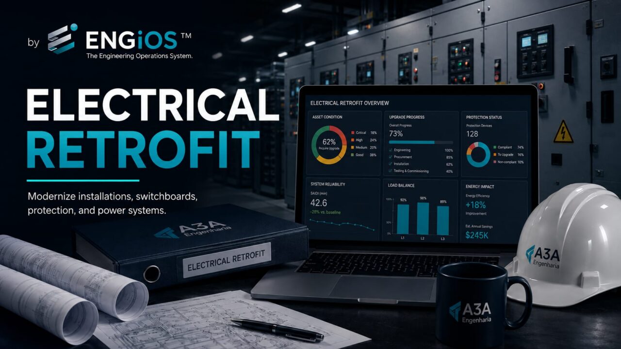
Understand when to carry out an electrical retrofit, how to diagnose existing installations, and how to plan modernization of switchboards, protection, substations, cutover, and commissioning.
Check it out!
Electrical retrofit is the planned modernization of an existing electrical installation to address obsolescence, restore safety and reliability, increase capacity, meet technical requirements, or prepare the system for new loads and operating conditions. Unlike simple corrective maintenance, a retrofit changes a relevant part of the electrical architecture in a coordinated manner, preserving what remains technically suitable and replacing or reconfiguring what limits performance, safety, or operational continuity.
The decision to modernize should not begin with selecting a new panel or piece of equipment. It begins with diagnosing the current condition, defining future needs, and analyzing how to intervene in an installation that often must remain in operation during the work. In industrial, corporate, healthcare, logistics, commercial, and critical-infrastructure environments, the greatest challenge is not only designing the final solution: it is migrating from the existing condition to the new configuration without losing technical control over risks, interfaces, protection, documentation, and operations.
What Is an Electrical Retrofit
An electrical retrofit is an engineering intervention in existing systems intended to modernize, upgrade, expand, or restore performance. It can range from replacing an obsolete main low-voltage switchboard to the coordinated renewal of a substation, feeders, distribution boards, protection, grounding, metering, automation, and documentation.
The term should not be confused with maintenance. Maintenance seeks to preserve or restore an asset’s function within its existing configuration. Retrofit changes that configuration to meet new technical, operational, or lifecycle conditions.
It is also not synonymous with a Brownfield project. The article on Brownfield Projects addresses the broader engineering context of existing facilities. Retrofit is one possible intervention in that context. An expansion, integration, or new line may be Brownfield without necessarily representing broad modernization of the electrical system.
Retrofit, upgrade, and expansion
These three objectives may coexist, but it is useful to distinguish them:
- retrofit: replaces or modernizes existing systems to recover performance, supportability, safety, or service life;
- upgrade: corrects conditions that do not meet technical, regulatory, or operational requirements;
- expansion: increases capacity for new loads, areas, or processes.
A project may, for example, replace an old main switchboard, upgrade protection, and simultaneously create new outgoing feeders for load expansion. In that case, the scope should address all three fronts in an integrated manner.
When an Electrical Retrofit Becomes Necessary
The need rarely arises from a single indicator. Usually, several warning signs accumulate until isolated interventions are no longer sufficient.
Typical triggers include:
- discontinued or unsupported equipment;
- difficulty replacing circuit breakers, relays, contactors, or components;
- load growth beyond the margin originally planned;
- recurrent overheating, failures, or shutdowns;
- switchboards with successive modifications and poor traceability;
- lack of selectivity or reliable protection settings;
- outdated documentation;
- limited expansion capacity;
- high maintenance risk;
- need for integration with automation, metering, or energy management;
- electrical-safety upgrades;
- change in facility use;
- renewal of generators, UPS systems, transformers, or critical systems;
- need to reduce downtime or improve operational continuity.
The presence of one of these factors does not automatically mean the entire installation should be replaced. A retrofit should preserve technically suitable assets whenever that makes sense over the lifecycle.
Diagnosis Comes Before Retrofit Design
Designing based on an assumed condition is one of the greatest risks in existing installations. The basis of a retrofit should be a diagnosis that determines what exists, how it is connected, what capacity is available, and which deficiencies actually need to be corrected.
This diagnosis may combine:
- document review;
- existing-condition survey;
- inspection of switchboards and equipment;
- diagram updates;
- load measurements;
- thermography;
- electrical testing;
- failure-history analysis;
- short-circuit and protection studies;
- grounding assessment;
- power-quality analysis;
- interviews with operations and maintenance teams.
When the condition must be formally documented before deciding on the investment, an Electrical Technical Report can structure the evidence, risks, and recommendations that will support definition of the retrofit.
Existing Documentation: Trust or Verify?
In older installations, design documents and reality often diverge. Emergency changes, expansions, replacements, and changes in use may have been executed without complete document updates.
Existing drawings should therefore be classified according to their degree of reliability. A single-line diagram may be used as a starting point, but not as absolute truth before field validation.
The Electrical As-Built process is particularly important when the retrofit depends on identifying feeders, devices, circuits, interconnections, and isolation points.
Configuration control from the outset
During a phased retrofit, the following may temporarily coexist:
- the old configuration;
- a temporary configuration;
- new equipment not yet commissioned;
- circuits already transferred;
- circuits still in the original condition;
- documents at different revisions.
Without configuration control, the operations team may work from an interpretation different from the one used by construction or commissioning. Document management must follow the physical changes to the system.
How to Decide Whether to Repair, Retrofit, or Replace
Before defining equipment, establish the actual condition of the installation, the load horizon, and the risks that justify modernization. A well-structured retrofit begins with diagnosis, not with a catalog.
Not every problem justifies complete replacement. The decision should compare alternatives and consider risk, cost, time, residual service life, and operational impact.
An analysis may consider:
| Criterion | Targeted repair | Partial retrofit | Broad replacement |
| Obsolescence | low | medium | high |
| Parts availability | adequate | limited | critical |
| Capacity margin | sufficient | restricted | insufficient |
| Operational risk | low | moderate | high |
| Documentation | reliable | incomplete | very poor |
| Expansion need | small | moderate | high |
| Integration complexity | low | medium | high |
| Expected service life | short extension | medium extension | new lifecycle |
The choice should not be based only on the lowest initial CAPEX. Keeping an asset that is inexpensive to repair but unsupported and highly likely to become unavailable may cost more over its lifecycle.
Load Survey and Installed Capacity
An electrical retrofit must determine whether the existing infrastructure can support current and future loads.
The analysis normally considers:
- measured demand;
- installed power;
- diversity;
- load profile;
- transformer capacity;
- cable and busbar capacity;
- switchboard limits;
- generator and UPS capacity;
- growth margin;
- critical and priority loads.
Simply adding nameplate ratings does not necessarily represent actual demand. Historical measurements and operating scenarios help avoid both undersizing and excessive expansion.
Retrofit of Main Switchboards, Distribution Boards, and Electrical Panels
Switchboards are often at the core of a retrofit because they concentrate distribution, protection, and switching. Over the years, they may accumulate modifications that reduce space, traceability, and maintainability.
A modernization design should assess:
- rated capacity;
- short-circuit withstand current;
- interrupting rating of devices;
- applicable form of separation and compartmentalization;
- busbars;
- ventilation and thermal dissipation;
- identification;
- accessibility;
- grounding;
- interlocks;
- space for expansion;
- integration with supervision or metering;
- physical interfaces with existing cables.
The Main Low-Voltage Switchboards and Electrical Panels solution explains the role of these assemblies in the system. In a retrofit, the specification must also consider how the old equipment will be removed and the new equipment connected.
Is reusing the old enclosure always a good idea?
No. In some cases, an internal refurbishment appears to reduce cost but may preserve structural, thermal, segregation, or verification limitations. In others, a high-quality panel may support a technically controlled upgrade.
The decision should consider assembly characteristics, documentation, manufacturer, applicable verifications, mechanical condition, and the impact of modifications. The objective is not to “make” modern components fit inside an old structure, but to preserve verifiable performance and safety.
Protection Must Be Recalculated When the Installation Changes
Changing transformers, cables, busbars, sources, generators, or protective devices changes the electrical behavior of the system.
For this reason, a retrofit should not simply copy old settings into new equipment. Depending on the scope, the following may be required:
- short-circuit study;
- protection coordination;
- selectivity study;
- curve review;
- interrupting-capacity analysis;
- relay-setting review;
- analysis of generator operating scenarios;
- incident-energy assessment.
The Guide to Electrical Studies in Power Systems explains how short circuit, protection, and selectivity relate. In a retrofit, these studies should reflect the future configuration and relevant intermediate states.
Arc Flash and Incident Energy in Retrofit Projects
Modernization can be an opportunity to reduce arc-flash risk. Replacing devices, changing settings, introducing faster protection, or reconfiguring the system can significantly alter incident energy.
The article on incident-energy calculation and NBR 17227 explains why the result depends on arcing current, clearing time, electrode configuration, working distance, and operating scenarios.
Instead of addressing the risk only through PPE, a retrofit makes it possible to consider engineering measures during design.
Retrofit of Medium-Voltage Substations
Existing substations may require modernization because of obsolete switchgear, relays, transformers, protection, metering, or supervisory systems.
The scope may include:
- switchgear replacement;
- relay modernization;
- protection and control upgrades;
- transformer renewal;
- grounding upgrades;
- interlock review;
- automation and supervision;
- medium-voltage cable renewal;
- access and signage upgrades;
- capacity expansion.
The maintenance, diagnosis, and modernization of medium-voltage substations service is a specific workstream when the issue is concentrated in the MV infrastructure.
Relay retrofit and digital protection
Replacing electromechanical or older digital relays can improve diagnostics, event recording, communications, and protection flexibility. However, the new relay must be parameterized based on the system, not merely copy old values without verification.
The following should also be defined:
- setting files;
- version control;
- test records;
- trip logic;
- interlocks;
- communications;
- time synchronization where applicable;
- backups and final documentation.
Cables and Feeders: Replace or Preserve
Modernizing panels does not necessarily mean replacing every cable. Existing feeders may be preserved if their condition, capacity, and compatibility are suitable.
The assessment may consider:
- conductor size and material;
- installation method;
- current-carrying capacity;
- voltage drop;
- length;
- termination condition;
- insulation resistance where applicable;
- thermal short-circuit withstand;
- coordination with protective devices;
- aging and environment.
A new panel with larger devices cannot simply be connected to an old feeder without verifying cable protection.
Grounding, Equipotential Bonding, and Continuity
Retrofits often expose long-standing grounding problems. Replacing panels, equipment, and cables may require review of protective conductors, grounding busbars, equipotential bonding, and interfaces with existing systems.
The analysis should preserve consistency among protective measures, grounding arrangements, and the devices used. Local changes made without understanding the existing architecture may introduce unwanted currents, lose continuity, or create inconsistent references.
Surge Protective Devices and Surge Protection
Modernization should also review the surge-protection strategy. Today’s electronic equipment may be more sensitive and integrated with networks, automation, and control systems.
The SPD assessment should consider its position in the system, coordination, installation characteristics, grounding, and interface with the lightning protection system when one exists. Modernizing switchboards is an opportunity to reorganize this protection coherently rather than add isolated devices without a defined architecture.
Generators and Emergency Power Sources
When a facility has emergency generation, any distribution retrofit must consider operation both with and without the generator.
The following should be assessed:
- available power;
- priority loads;
- transfer;
- interlocks;
- protection;
- grounding and neutral;
- short-circuit current in generator mode;
- load rejection and load pickup;
- autonomy related to the process;
- periodic testing.
The protection system may behave differently when supplied by a generator, especially because the available short-circuit current is lower than when supplied by the utility.
UPS Systems and Critical Loads
Data centers, telecommunications, security, automation, industrial processes, and other critical loads may depend on UPS systems. Modernization should consider topology, redundancy, autonomy, bypass, distribution, and maintenance strategy.
Replacing the UPS without reviewing cables, protection, batteries, bypass, and loads may simply move the bottleneck to another part of the system.
In critical environments, transfer and failure tests should be part of retrofit commissioning.
Metering, Energy Management, and Automation
A retrofit can increase installation observability. Digital meters, analyzers, communications, and integration with BMS, SCADA, or management platforms can monitor demand, energy, events, and operating conditions.
But metering needs a defined purpose. Installing dozens of meters without a data architecture, naming conventions, retention policy, and operational use creates information without management.
The specification should define:
- required quantities;
- metering points;
- required accuracy;
- communication protocol;
- integration;
- storage;
- alarms;
- operational responsibilities.
Electrical Retrofit and NR-10
Modernization must be compatible with the safety requirements applicable to electrical installations and work involving electricity. NR-10 addresses control measures, documentation, procedures, design, authorized workers, and intervention conditions.
In September 2026, the new text consolidated by MTE Ordinance No. 737/2026 has already been published, with entry into force scheduled for June 1, 2027. The previous text remains in force through May 31, 2027. Projects and works that span this period should consider the regulatory schedule and prepare for the transition.
The NR-10 Compliance Guide organizes the main documentary and technical workstreams related to the standard.
NBR 5410 and Low-Voltage Modernization
For low-voltage installations, ABNT NBR 5410 is a central reference for design, protection, construction, and verification. A retrofit may require review of conditions that were accepted at another time but no longer represent the best technical solution or need to be upgraded as a result of the intervention.
The design should clearly define which parts will be modified, how interfaces with preserved systems will be handled, and which verifications will apply to the renovated scope.
NBR 14039 and Medium Voltage
When the intervention reaches installations from 1.0 kV to 36.2 kV, ABNT NBR 14039:2021 becomes an essential reference for the medium-voltage infrastructure covered by the project.
This requires attention to arrangement, protection, access, grounding, devices, operation, and installation-specific conditions. An MV retrofit should not be treated as a simple replacement with equivalent equipment.
How to Plan a Retrofit Without Shutting Down Operations
The outage window is a technical design requirement. It influences temporary architecture, cutover sequence, prefabrication, crew size, and rollback strategy.
In many facilities, the installation cannot simply be shut down for several days. The design must be developed around the available intervention windows.
The strategy may involve:
- phased execution;
- temporary power;
- temporary switchboards;
- gradual circuit transfer;
- temporary redundancy;
- night or weekend interventions;
- coordinated outages;
- contingency for returning to the previous condition.
This strategy should be developed during design. Leaving the migration sequence entirely for the contractor to solve in the field transfers critical risk to the moment of greatest operational pressure.
Outage window is a design requirement
The maximum acceptable downtime affects technology, installation method, prefabrication, connections, temporary equipment, and crew size.
The outage window should therefore be treated as a requirement, not as late-stage logistics information.
Cutover: The Highest-Risk Moment
Cutover is the actual transfer of load or function from the old system to the new one. It may involve switching, disconnection, connection, parameterization, energization, testing, and release.
A cutover plan should define:
- initial condition;
- responsible parties;
- shutdown sequence;
- isolation points;
- checks before intervention;
- connection steps;
- tests before energization;
- energization sequence;
- success criteria;
- abort criteria;
- rollback plan;
- expected final condition.
The more critical the installation, the less room there is for improvised decisions during cutover.
Rollback: How to Return Safely
A return plan does not mean expecting the project to fail. It means recognizing that intervention on a critical asset may reveal conditions that were not previously visible.
Rollback must define how far the system can be returned, which materials and resources must be available, and how long reversal will take.
In some interventions, after a certain physical cut the return is no longer simple. This point of no return must be understood and approved before execution.
Temporary Installations Are Also Part of Engineering
Temporary power supplies, temporary cables, mobile generators, and auxiliary switchboards used during migration must be sized, protected, identified, and controlled.
A temporary solution may operate for hours or weeks. Being temporary does not eliminate safety and reliability requirements appropriate to its function.
Constructability and Access
Designing the new panel is only part of the problem. It is necessary to verify that it can reach the location and be installed.
Constructability analysis considers:
- door and corridor dimensions;
- floor capacity;
- lifting;
- required dismantling;
- cable bend radius;
- termination positions;
- maintenance space;
- interferences;
- need for civil works;
- ventilation and thermal dissipation.
In retrofit projects, these constraints may determine the final equipment arrangement.
Compatibility With Existing Interfaces
New equipment must coexist with preserved components. Compatibility is not only electrical.
The following interfaces should be verified:
- mechanical;
- electrical;
- communications;
- control;
- protection;
- auxiliary power;
- supervision;
- physical space;
- maintenance.
Equipment that is superior on paper may be unsuitable if it requires changes incompatible with the existing infrastructure.
Equipment Procurement for Retrofit Projects
Procurement must incorporate installation and migration constraints. Specifying only current, voltage, and power is not enough.
A technical requisition may include:
- maximum dimensions;
- cable entry and exit positions;
- access requirements;
- short-circuit rating;
- communication interfaces;
- accessories;
- spare parts;
- documentation;
- FAT;
- field assistance;
- training;
- delivery lead time;
- future replacement strategy.
Long-lead equipment should be identified early so procurement does not become the critical path for implementation.
FAT Before Taking Equipment to the Field
A Factory Acceptance Test makes it possible to verify part of the functionality before field mobilization. In retrofit projects, this is valuable because the field window is usually short.
Depending on the equipment, FAT may verify:
- documentation;
- assembly;
- identification;
- control logic;
- interlocks;
- communications;
- parameterization;
- input and output simulation;
- device operation;
- factory test records.
FAT does not eliminate SAT and commissioning because it does not fully reproduce the installation’s real interfaces.
Field Preparation Before the Outage
Everything that can be completed before the critical window should be brought forward.
This may include:
- installation of structures;
- advance cable pulling;
- installation of auxiliary panels;
- relay configuration;
- termination preparation;
- communication tests;
- identification;
- preassembly of kits;
- validation of tools and equipment;
- readiness meeting.
The goal is to reduce unpredictable activities during the outage.
Readiness Review Before Cutover
A formal readiness review verifies whether the project is actually prepared to begin the intervention.
Essential questions include:
- Is the design released for construction?
- Are critical materials available?
- Is the team mobilized?
- Are permits and procedures approved?
- Is test equipment available and suitable?
- Has device configuration been validated?
- Have backups been completed?
- Is rollback defined?
- Does operations understand the sequence?
- Are energization criteria clear?
If a critical answer is negative, postponing the intervention may be safer than starting a window without the conditions needed to finish it.
Tests Before Energization
Before energizing a modernized circuit, the checks specified in the design, inspection plan, and applicable procedures should be completed.
Depending on the system, this may involve:
- visual inspection;
- torque and connections according to procedure;
- continuity;
- insulation;
- ratio and polarity of instrument transformers;
- relay tests;
- interlocks;
- phase identification;
- communications;
- control logic;
- grounding verification;
- safety checklists.
Energization should not be used as the first test of an assembly that has not yet been verified.
Commissioning the Electrical Retrofit
Energizing does not mean accepting. A retrofit should end with tests, documentation, recorded settings, As-Built documentation, and evidence that the intended operating scenarios actually work.
Learn about Commissioning and Acceptance of Electrical Installations
Commissioning confirms through evidence that the modernized systems meet requirements and operate in an integrated manner.
The process should verify not only individual components but also operating scenarios. Examples include:
- normal operation;
- loss of source;
- transfer to emergency supply;
- protection operation;
- interlocks;
- alarms;
- metering;
- integration with supervision;
- recovery after failure;
- behavior of critical loads.
The Commissioning and Technical Acceptance of Electrical Installations service structures this stage independently from the simple physical completion of installation work.
Acceptance Is Not the Same as Energization
A system may be energized and still not be technically accepted. Energization only demonstrates that the system could be placed under voltage under certain conditions.
Acceptance should consider:
- completed tests;
- criteria satisfied;
- punch-list items classified;
- documentation delivered;
- updated As-Built;
- backups provided;
- settings recorded;
- training completed where required;
- operational safety established.
Confusing “it turned on” with “it was delivered” is a recurring source of technical liability.
As-Built Documentation Should Be Updated During Implementation
Recording changes only at the end tends to produce incomplete documentation. The process should use redlines, field records, and change control throughout construction.
At completion, the As-Built must represent the condition actually implemented, including devices, settings, circuits, identification, and relevant interfaces.
Change Management During the Retrofit
Existing installations often reveal unforeseen conditions when opened. This does not remove the need for governance over changes.
A change should record:
- condition found;
- impact;
- proposed solution;
- people responsible for the analysis;
- approval;
- document change;
- cost and schedule impact;
- need for retesting.
The phrase “it was solved in the field” is not sufficient to maintain traceability for a critical intervention.
How to Estimate Retrofit CAPEX
The estimate must reflect more than the price of new equipment. In Brownfield work, indirect implementation costs can be significant.
CAPEX may include:
- main equipment;
- installation materials;
- cables and terminations;
- civil works;
- dismantling;
- transport and lifting;
- temporary systems;
- engineering;
- electrical studies;
- supervision and management;
- FAT;
- commissioning;
- special work windows;
- final documentation;
- contingency appropriate to uncertainty.
An apparently cheaper alternative may require more downtime or more field adaptations.
OPEX, Maintenance, and Lifecycle Cost
The decision should also consider future costs. Modern equipment may reduce maintenance, facilitate diagnostics, and improve parts availability, but may introduce licenses, support contracts, or technological dependency.
The alternatives comparison should consider:
- preventive maintenance;
- spare parts;
- manufacturer support;
- availability of technicians;
- expected service life;
- consumption and losses;
- cost of downtime;
- future upgradeability;
- training.
Phased Retrofit or a Single Intervention
The strategy depends on criticality, budget, available windows, and interdependencies.
Phased retrofit
It can reduce immediate expenditure and operational impact, but requires greater control over interfaces between new and old equipment.
Concentrated intervention
It can simplify the final configuration and reduce the period of coexistence between technologies, but requires a larger window and more rigorous preparation.
The decision should be made during planning, not improvised during construction.
Prioritization by Criticality
When it is not possible to modernize everything, assets can be prioritized according to risk and impact.
Typical criteria include:
- safety risk;
- probability of failure;
- impact of downtime;
- obsolescence;
- lack of parts;
- load served;
- operational importance;
- capacity margin;
- maintenance history.
This analysis helps build a multi-year modernization roadmap.
Retrofit in Critical Facilities
Hospitals, data centers, operations centers, telecommunications facilities, continuous-process industrial plants, and other critical infrastructure have very low tolerance for downtime.
In these environments, the design must treat redundancy architecture, transfer sequence, temporary sources, rollback, and integrated testing as core requirements.
Engineering must work together with operations to define permitted and prohibited states during migration.
The Role of Owner’s Engineering
When multiple suppliers, contractors, and manufacturers are involved, the owner may need an independent engineering function to preserve requirements and coordinate decisions.
Owner’s Engineering may support:
- diagnosis;
- requirements definition;
- design review;
- technical procurement;
- bid evaluation;
- change control;
- inspection;
- testing;
- commissioning;
- technical acceptance.
This approach reduces the risk of the solution being defined exclusively by the commercial convenience of a specific supplier.
How to Contract an Electrical Retrofit
The contracting scope should clearly state the known condition, uncertainties, and each party’s responsibilities.
A Terms of Reference or specification may define:
- retrofit objective;
- installations included;
- data supplied by the owner;
- surveys to be performed by the contractor;
- continuity requirements;
- maximum outage windows;
- required studies;
- design criteria;
- equipment and interfaces;
- FAT and SAT;
- commissioning;
- As-Built documentation;
- training;
- spare parts;
- acceptance criteria.
Contracting only the “replacement of the main switchboard” without defining interfaces and criteria transfers critical decisions to the execution phase.
Common Electrical Retrofit Mistakes
Buying equipment before engineering is finalized
This can create physical, electrical, or operational incompatibilities and limit design alternatives.
Designing only from old drawings
Documentation may not reflect changes made over the years.
Ignoring short circuit and selectivity
New devices must be compatible with the system’s future configuration.
Leaving cutover for the contractor to solve
The migration sequence is part of design and risk management.
Failing to plan rollback
Without a return strategy, an unforeseen condition can turn a short window into prolonged downtime.
Treating energization as acceptance
Tests, documentation, and punch-list items must be completed according to previously defined criteria.
Updating As-Built only at the end
This increases the chance of losing changes made during implementation.
Indicators of a Successful Retrofit
A retrofit should not be assessed only by schedule and cost. Useful technical indicators include:
- reduction in recurrent failures;
- increase in capacity margin;
- reduction in obsolete equipment;
- availability of parts and support;
- improved selectivity;
- lower operational risk;
- updated documentation;
- commissioning test performance;
- fewer punch-list items after energization;
- improved observability and maintenance.
Readiness Checklist Before Starting the Project
Before moving forward, the owner should be able to answer:
- What problem must the retrofit solve?
- What load horizon should be considered?
- Which assets are obsolete?
- Is the documentation reliable?
- What outage windows are available?
- Which loads cannot stop?
- Is temporary power available?
- Which studies need to be updated?
- Which interfaces must be preserved?
- What CAPEX level is acceptable?
- How will acceptance be performed?
- Who will maintain configuration control during construction?
If these answers do not yet exist, the correct step is to structure the diagnosis and engineering before purchasing equipment.
Final Considerations
Electrical retrofit is an engineering process for modernizing existing installations without losing control over safety, continuity, protection, documentation, and lifecycle. The quality of the outcome depends far more on diagnosis, migration strategy, and acceptance criteria than on simply selecting new equipment.
In Brownfield systems, the final solution must be technically suitable and executable within the facility’s real constraints. This requires a reliable survey, updated electrical studies, cutover planning, configuration control, coordinated procurement, testing, and final documentation.
When this approach is followed, retrofit ceases to be a sequence of isolated replacements and becomes a structured modernization program capable of reducing obsolescence, restoring reliability, and preparing the infrastructure for new demands.
Technical References
[1] ASSOCIAÇÃO BRASILEIRA DE NORMAS TÉCNICAS. ABNT NBR 5410: Instalações elétricas de baixa tensão. Rio de Janeiro: ABNT.
[2] ASSOCIAÇÃO BRASILEIRA DE NORMAS TÉCNICAS. ABNT NBR 14039:2021: Instalações elétricas de média tensão de 1,0 kV a 36,2 kV. Rio de Janeiro: ABNT.
[3] ASSOCIAÇÃO BRASILEIRA DE NORMAS TÉCNICAS. ABNT NBR IEC 61439-1: Conjuntos de manobra e comando de baixa tensão — Parte 1: Regras gerais. Rio de Janeiro: ABNT.
[4] BRAZIL. Ministry of Labor and Employment. Regulatory Standard No. 10 (NR-10) — Safety in Electrical Installations and Services. Available at: https://www.gov.br/trabalho-e-emprego/pt-br/acesso-a-informacao/participacao-social/conselhos-e-orgaos-colegiados/comissao-tripartite-partitaria-permanente/normas-regulamentadora/normas-regulamentadoras-vigentes/norma-regulamentadora-no-10-nr-10.
Frequently Asked Questions
It is the planned modernization of an existing electrical installation to address obsolescence, restore safety and reliability, increase capacity, or adapt the system to new technical and operational conditions.
Maintenance preserves or restores an asset’s function within its existing configuration. Retrofit changes that configuration in a coordinated manner, replacing or reconfiguring systems to meet new needs.
No. The design should diagnose which assets are still suitable and which need replacement. Cables, switchboards, and equipment may be preserved when their capacity, condition, protection, and service life are compatible with the future solution.
Yes, in many cases. This requires phased planning, defined outage windows, temporary systems, cutover, rollback, and testing. The strategy must be developed during design.
Because changes to sources, transformers, cables, busbars, or protection modify system behavior. The settings and devices in the new configuration must be verified for the future condition.
When obsolescence, lack of parts, limited capacity margin, recurring risks, poor documentation, or successive modifications indicate that small corrections will not solve the system problem sustainably.
Complementary Technical Materials
Related Solutions
- Main Low-Voltage Switchboards and Electrical Panels: design, protection, and compliance
- Electrical Safety and NR-10 Compliance: design, risks, documentation, and controls
- Power for Critical Infrastructure: redundancy, UPS, generation, and continuity
Related Services
- Retrofit and Upgrades: modernization, compliance, and operational continuity
- Electrical Engineering Services: design, inspections, studies, technical reports, and commissioning
- Maintenance, Diagnosis, and Modernization of Medium-Voltage Substations
- Commissioning and Technical Acceptance of Electrical Installations
Core Content on the Topic
- Brownfield Projects: engineering in existing facilities, surveys, As-Built, and retrofit
- Electrical Technical Report: what it is, when it is needed, inspections, testing, and deliverables
Related Technical Content
- Electrical As-Built: survey, diagrams, circuits, switchboards, and final documentation
- Guide to Electrical Studies in Power Systems: short circuit, protection, selectivity, and power quality
- NR-10 Compliance Guide: design, PIE, risks, and the 2027 transition
- Incident-energy calculation: how NBR 17227 guides arc-flash risk analysis
