
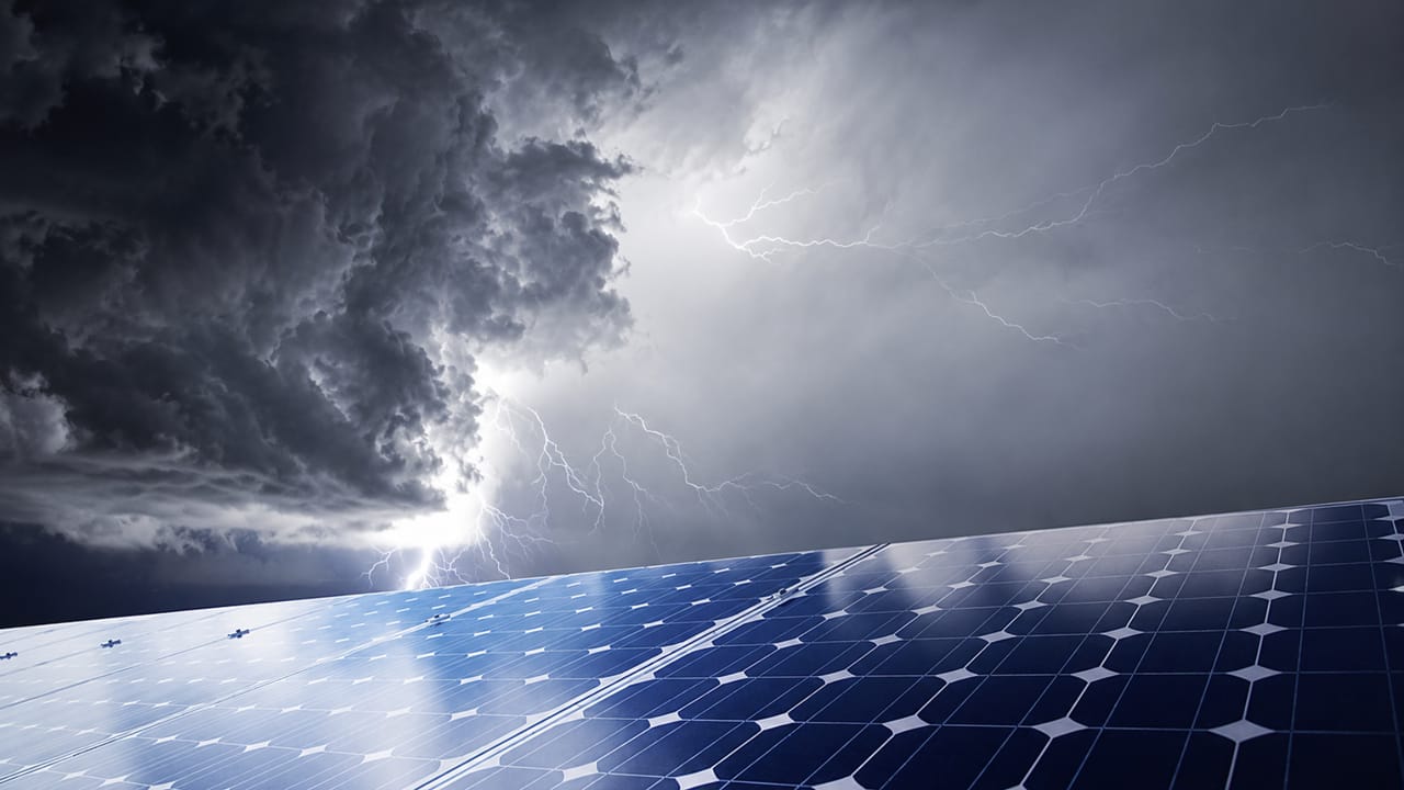
Technical guide to surge protection design for photovoltaic systems: SPDs on the DC and AC sides, UCPV, UOC MAX, ISCPV, classes, LPS, distances, coordination and maintenance.
Check it out!
Photovoltaic systems require a specific approach to surge protection. The direct-current side is not simply an extension of an alternating-current low-voltage distribution board: the PV array behaves as a current source, may operate at hundreds or thousands of volts DC, has an open-circuit voltage that depends on temperature, and exhibits fault behavior different from that found in conventional AC circuits. Therefore, the SPD used on the DC side must be explicitly intended for photovoltaic applications and selected within the complete system architecture.
Proper protection also does not end on the DC side. A photovoltaic system includes the array, strings, junction boxes, cables, inverter, AC distribution board, grounding system, equipotential bonding, possibly an LPS, communications, monitoring, and interfaces with other building systems. A surge may enter or be induced through more than one path. The engineering solution must coordinate the SPDs on the DC and AC sides, devices integrated into the inverter, signal lines, and lightning protection measures.
ABNT NBR IEC 61643-32:2022 provides the specific principles for selection, installation, and coordination of SPDs in photovoltaic installations, while ABNT NBR IEC 61643-31:2022 establishes requirements and test methods for SPDs intended for the DC side. ABNT NBR 16690:2019 addresses design requirements for photovoltaic arrays, and ABNT NBR 5419-4:2026 places the system within the broader framework of Surge Protection Measures, Lightning Protection Zones, equipotential bonding, routing, and SPD coordination.
Correctly sizing the protection means answering, among others, the following questions: what overvoltage may reach the array and inverter; what test class is required; what UCPV value withstands the highest open-circuit voltage under service conditions; what surge current must be conducted; what ISCPV is compatible with the available short-circuit current; where the SPDs must be installed; when a second protection stage is required; and how the protection integrates with the LPS, grounding, and communication lines.
Why surge protection in photovoltaic systems is different
The DC side of a photovoltaic installation has specific electrical characteristics. ABNT NBR 16690 notes that PV arrays can produce and sustain electric arcs with currents that are not much higher than normal operating currents. ABNT NBR IEC 61643-31, in turn, considers in its tests that photovoltaic generators behave as current sources, that their output varies with irradiance and temperature, and that the short-circuit current is only slightly higher than the current at the maximum power point.
This characteristic changes how an SPD failure is evaluated. A degraded varistor may enter a low-impedance state, but the resulting current may not always be sufficient to cause rapid operation of a fuse sized only for maximum-irradiance conditions. End-of-life protection and OCFM or SCFM behavior, addressed by the specific standards for PV SPDs, therefore become an important part of system safety.
In addition, the DC side may operate up to 1,500 V in installations covered by ABNT NBR IEC 61643-31 and 61643-32. The actual array voltage is not constant: open-circuit voltage increases under low-temperature conditions. Therefore, selecting an SPD only by the nominal voltage indicated for the inverter or by the sum of voltages under STC conditions may result in insufficient UCPV.
For the device’s general parameters, see SPD: what it is, what it is used for, classes, sizing and installation.
Which equipment and circuits need protection
The analysis must consider the entire system, not only the inverter input. A typical architecture includes modules, strings, subarrays, string boxes, DC cables, inverter inputs, AC output, distribution boards, metallic structures, grounding, equipotential bonding, LPS, RS-485, Ethernet, weather sensors, supervisory systems, and other associated metallic services.
This avoids a recurring error: installing SPDs only on the inverter’s AC side and assuming that the entire installation is protected.
Where surges in a photovoltaic installation come from
ABNT NBR IEC 61643-32 identifies different sources of overvoltage. Within the terminology of the lightning protection series, there may be sources associated with direct flashes to the structure, flashes near the structure, flashes to electrical lines, and flashes near the lines. Switching surges originating from the grid and phenomena associated with the power electronics themselves must also be considered.
In a rooftop array, DC cables normally run through exposed areas, close to the metallic structure of the modules and, in many cases, to the LPS. The electromagnetic field from a nearby lightning discharge can induce significant voltages in the loops formed by the cabling. For this reason, ABNT NBR 16690 requires the positive and negative conductors of the same string, together with the associated grounding/equipotential-bonding conductors, to be grouped in order to minimize loop area.
In larger installations, the combination of long distances, multiple grounding points, and interconnections between structures changes the distribution of impulse currents. In a ground-mounted photovoltaic plant, the assessment should not simply replicate the solution adopted for a building rooftop.
An SPD on the DC side is not the same product used on the AC side
The SPD connected to the DC side of the photovoltaic generator must be explicitly intended for this service and comply with ABNT NBR IEC 61643-31. The standard establishes performance and safety requirements specific to PV sources, including continuous operating conditions, permanent current, failure behavior, disconnection, and tests using sources that reproduce the behavior of a photovoltaic array.
SPDs connected to the AC side of the installation, however, are covered by ABNT NBR IEC 61643-11 and by the criteria applicable to low-voltage networks.
This distinction is essential because direct current has no natural zero crossing every half-cycle, making arc extinction more critical. In addition, the relationship between operating current and array short-circuit current differs from that of a conventional AC source.
UCPV: the maximum continuous operating voltage of a photovoltaic SPD
On the DC side, the key continuous-voltage parameter is UCPV. ABNT NBR IEC 61643-32 establishes that the maximum continuous operating voltage for all SPD protection modes must be greater than or equal to the maximum open-circuit voltage of the photovoltaic array under all service conditions:
UCPV ≥ UOC MAX
This requirement appears simple, but calculating UOC MAX requires care. The module’s catalog Voc value is normally stated under standardized test conditions. Module voltage increases as cell temperature decreases.
The installation’s lowest temperature may determine the SPD
ABNT NBR 16690 establishes that the maximum array voltage must consider Voc corrected for the lowest expected operating temperature. When the manufacturer provides temperature coefficients, they must be used. For certain silicon modules, the standard also provides correction factors when this information is unavailable.
Therefore, specifying a “1,000 Vdc SPD” simply because the inverter is commercially described as a 1,000 V unit may be inadequate if the corrected UOC MAX exceeds the device’s permissible voltage.
The calculation record should include the number of modules in series, Voc, temperature coefficient or standard correction factor, lowest design temperature, resulting UOC MAX, SPD UCPV for each protection mode, and the maximum permissible voltage of the inverter and other components.
UCPV and the +/−, +/ground and −/ground protection modes
Photovoltaic systems may be unearthed, may have functional grounding, or may use specific topologies defined by the inverter. ABNT NBR IEC 61643-32 shows different internal SPD connection arrangements for grounded and ungrounded PV sources.
The designer must not analyze only the voltage between positive and negative. Under certain fault conditions, the +/ground and −/ground potentials may shift. The SPD manufacturer must declare behavior compatible with the modes in which the device will be used.
Up and Uw: surviving continuous voltage is not enough
UCPV answers the question of what voltage the SPD can withstand continuously. It does not indicate the voltage that will be applied to the equipment during a surge.
The voltage protection level Up must be compared with the impulse withstand voltage Uw of the protected equipment. ABNT NBR IEC 61643-32 generally recommends, under the conditions described in the standard, a margin in which Up is less than or equal to 0.8 times Uw.
ABNT NBR 5419-4:2026 develops this concept further by addressing the effective protection level at the branch, Up/f, which includes not only the catalog Up but also the inductive voltage drop in the SPD connection conductors.
Up/f: why a good SPD may provide poor protection when installed incorrectly
For voltage-limiting SPDs, ABNT NBR 5419-4:2026 considers, in simplified form:
Up/f = Up + ΔU
The ΔU component depends on the length, geometry, waveform, and current carried by the connecting cables. As an order-of-magnitude reference for SPDs at the entrance of an installation, the standard gives approximately 0.1 kV per kA per meter. Thus, a 1 m connection carrying 10 kA may add approximately 1 kV to the effective protection level.
This is why the standards insist on short connections. In photovoltaic protection, ABNT NBR IEC 61643-32 recommends that the total length of SPD connecting cables be as short as possible and, preferably, no more than 0.5 m in the configurations covered.
Discharge current: In, Iimp and Imax in the PV system
The discharge current must be defined according to the class and the expected stress at the installation point. Capacity should not be selected using the generic rule “the more kA, the better.”
For Class II SPDs in applications covered by ABNT NBR IEC 61643-32, the indicated minimum nominal discharge current In is 5 kA, 8/20 µs waveform, per protection mode. Higher values may provide additional margin and service life, but they must be related to the surge environment and the other parameters.
When partial currents from direct lightning discharges may flow through the system, Class I and Iimp criteria apply. Selection depends on the LPS architecture, protection level, current division, and installation configuration.
The article 20 kA, 40 kA, 45 kA or 60 kA SPD examines the difference between In, Imax and Iimp in greater detail.
When to use Class I or Class II in photovoltaic systems
The decision depends mainly on the source of the stress and integration with the LPS. ABNT NBR IEC 61643-32 distinguishes scenarios with no external LPS, an installation with an LPS where the separation distance is maintained, and an installation with an LPS where that distance cannot be maintained.
Without an external LPS, protection against induced surges normally leads to the use of Class II SPDs on the DC side, in addition to the protection required on the AC side.
When an LPS exists and the separation distance is maintained, the possibility of direct lightning current flowing through the PV system is reduced. When the separation distance cannot be maintained, the metallic array structure must be integrated into the equipotential bonding and partial currents may flow through the associated circuits; under this condition, Class I-tested SPDs are required at the corresponding points in the architecture.
The difference between the test regimes is discussed in greater depth in Class 1, Class 2 and Class 3 SPDs.
LPS separation distance: a design parameter
On a rooftop with photovoltaic modules and an LPS, the separation distance directly affects the surge-protection architecture. When separation can be maintained between the air-termination/down-conductor system and the metallic structures and cables of the PV system, the probability of direct lightning current flowing through unintended paths is reduced.
When the separation distance cannot be met, equipotential interconnection is no longer optional and the conductors must withstand the expected share of current. SPD selection must also consider Class I and the corresponding energy.
This is a point at which the LPS design and photovoltaic design must be coordinated. Installing modules later on a building protected by an LPS without reassessing air terminals, distances, down conductors, equipotential bonding, and SPM may change the original protection assumptions.
For system-level integration among the LPS, LPZs, SPDs and protection of internal systems, see NBR 5419-4: internal LPS, SPDs and system protection.
Does the photovoltaic system share the rooftop with an LPS, or is the separation distance not met?
The Surge Protection Measures (SPM) Design coordinates the LPS, partial lightning current, Class I/II SPDs, equipotential bonding, routing, DC/AC SPDs, and protection of inverter interfaces before implementation.
Where to install SPDs on the DC side
The location must protect both the inverter and the array, considering the length of the section between them. ABNT NBR IEC 61643-32 uses 10 m as an important reference.
When the distance between the array and inverter is less than 10 m, one set of SPDs may be sufficient under certain conditions. When this distance is equal to or greater than 10 m, two sets of SPDs on the DC side are normally required: one near the inverter and another near the array or at the corresponding end of the circuit.
The protection points may be located in a string box, junction box, DC distribution board, DC input of the inverter, or an intermediate panel. The decision must reflect the actual architecture, not a universal installation rule.
Where to install SPDs on the AC side
On the AC side, the photovoltaic system interfaces with the low-voltage installation of the building or plant. The protection must consider the main distribution board, the point of connection, and the inverter.
ABNT NBR IEC 61643-32 recommends an SPD near the origin of the electrical installation. When the distance between this SPD and the inverter is equal to or greater than 10 m, an additional SPD adjacent to the inverter is recommended. This logic is consistent with ABNT NBR 5410 and ABNT NBR 5419-4: the greater the length and loop area between the SPD and the equipment, the greater the possibility of induced voltage and propagation.
Does the inverter’s internal SPD eliminate the need for an external SPD?
Not necessarily. ABNT NBR 16690 recognizes that certain power-conditioning units or inverters have built-in surge protection, but states that external SPDs may still be required. When both are present, coordination between the built-in protection and the external SPD must be verified with the equipment supplier.
The statement “the inverter has a Class II SPD” is not sufficient to eliminate the external analysis. It is necessary to know where the element is connected, its Up and UCPV, the In/Iimp it can withstand, its failure architecture, the distance to the cable entry point, and whether coordination with the external SPD is declared.
ISCPV: the rated short-circuit current of the SPD on the DC side
ISCPV is a fundamental and frequently overlooked parameter. ABNT NBR IEC 61643-32 establishes that the SPD rated short-circuit current must be greater than or equal to the maximum short-circuit current of the photovoltaic array at the installation point:
ISCPV ≥ ISC MAX
The available fault current depends on the number of parallel strings, irradiance, topology, and other connected sources. In systems with batteries, currents may be much higher and additional requirements must be considered.
The SPD and its disconnector must be able to reach a safe failure mode under the possible PV-generator conditions. The protection must not be sized only to interrupt the highest current; it must also operate when irradiance is low.
OCFM and SCFM: how a photovoltaic SPD must fail safely
ABNT NBR IEC 61643-31 and ABNT NBR IEC 61643-32 address two relevant failure behaviors.
OCFM — Open-Circuit Failure Mode: the SPD transitions to high impedance or an open circuit. Surge protection is lost, but the degraded component is safely removed from the circuit.
SCFM — Short-Circuit Failure Mode: the SPD transitions to low impedance or a safe short circuit under the specified conditions, requiring the architecture to be compatible with that condition.
Not every photovoltaic system or inverter technology can tolerate a permanent short circuit to ground. The specification must comply with the manufacturer’s data and the electrical configuration of the array.
Backup protection in direct current requires specific analysis
On the AC side, the relationship among SPD, circuit breaker/fuse, short-circuit current, and continuity is detailed in SPD and Circuit Breaker.
On the photovoltaic DC side, the characteristics of the PV source must also be considered. Short-circuit current does not increase in the same proportion observed in low-impedance sources, and arc extinction is more difficult. ABNT NBR 16690 highlights the possibility that a fuse sized for the array’s maximum current may fail to disconnect a degraded SPD under low-irradiance conditions.
The specification must follow the tested and manufacturer-declared configuration, including the internal or external disconnector, fuses, and any other required elements.
Coordination between SPDs on the DC and AC sides
The presence of multiple SPDs does not guarantee coordinated protection. The devices must share energy and limit voltage in a manner compatible with their position and with the protected equipment.
Coordination must consider test class, expected energy/current, Up and Up/f, UCPV on the DC side and Uc on the AC side, distance between stages, cabling impedance, SPD technology, inverter internal protection, and manufacturer instructions.
The article SPD Coordination examines this responsibility specifically.
Grounding and equipotential bonding in the photovoltaic system
An SPD does not eliminate a surge: it creates a controlled path for impulse current and limits potential differences. This requires a low-impedance equipotential reference and a coherent grounding architecture.
ABNT NBR 16690 distinguishes functional grounding, grounding for lightning protection, and equipotential bonding of conductive parts. Where a separate grounding electrode is provided for the PV array, it must be interconnected with the installation’s main grounding terminal.
More important than memorizing a conductor cross-section is identifying its electrical function: conventional equipotential bonding, conduction of induced current, conduction of partial lightning current, or a function equivalent to a down conductor.
Are the photovoltaic system’s grounding and equipotential bonding undocumented or have they been expanded over time?
The Grounding Design makes it possible to verify and coordinate electrodes, protective conductors, equipotential bonding, metallic structures, and interfaces with the LPS/SPM before specifying SPD discharge paths.
See also Grounding and Equipotential Bonding.
Routing and reduction of loop area
ABNT NBR 16690 requires grouping the positive and negative conductors together with the associated grounding/equipotential-bonding conductors. This measure reduces loop area and, consequently, the voltage induced by the magnetic field of a lightning discharge.
In SPM terms, ABNT NBR 5419-4 addresses routing and shielding as basic protection measures, together with equipotential bonding, coordinated SPDs, and isolating interfaces.
Long DC cables and additional protection
ABNT NBR 16690 recommends special attention to long conductors; extensive main array cables may require additional SPDs or shielding measures. This criterion complements the 10 m reference in ABNT NBR IEC 61643-32 for locating protection stages.
Signal, monitoring, and communication lines must also be included in the design
An inverter or supervisory system may be protected on the power side and remain vulnerable through a metallic communication port. ABNT NBR IEC 61643-32 establishes that, when SPDs are required for power circuits, the signal and telecommunications circuits that are part of the PV system must also be considered.
This analysis includes metallic Ethernet, RS-485, weather sensors, digital and analog inputs, communication between inverters, lines to supervisory or SCADA systems, and external equipment.
For this interface, see SPDs for data lines, CCTV, automation and telecommunications.
Rooftop installation with an LPS
On rooftops, the first question is whether the photovoltaic system can maintain the separation distance from the external LPS. If it can, the preferred solution is to avoid direct coupling of lightning current into the PV structures. If it cannot, the metallic module structure must be integrated in accordance with the LPS and equipotential-bonding design, and the selection of Class I SPDs must consider partial lightning currents.
Subsequent installation of PV on an existing rooftop should trigger a review of the lightning protection design whenever it changes geometry, air terminals, distances, metallic parts, or relevant electrical routes.
Ground-mounted photovoltaic plants
Ground-mounted plants follow a different logic. ABNT NBR IEC 61643-32 specifically addresses extensive installations with multiple grounding points and a meshed grounding system. Current distribution depends on the physical topology, grounding arrangements, soil resistivity, cable lengths, number of paths, and SPD impedance.
In complex systems, the standard allows transient-network programs to be used to calculate the expected current division. This means that a standardized specification of “40 kA SPD in every string box” may be technically weak.
Systems with microinverters
Microinverters reduce or eliminate long high-voltage DC sections, but they do not eliminate the need for surge protection. The architecture instead involves multiple devices distributed across the rooftop, connected by AC circuits and frequently associated with communication lines.
The position of the microinverters, extent of the rooftop AC network, proximity to the LPS, grounding of structures, protection at the AC panel, need for distributed SPDs, and communication interfaces must be assessed.
Systems with batteries and energy storage
The presence of batteries radically changes the short-circuit current available on the DC side. ABNT NBR IEC 61643-31 states that SPDs for PV systems with energy storage are not directly covered by its scope.
Therefore, a hybrid system should not be treated by applying the same array SPD to battery circuits. The standard applicable to energy storage, manufacturer characteristics, maximum voltage, short-circuit current, grounding mode, and coordination with converters must be analyzed.
How to prepare the technical specification for SPDs in a PV system
An engineering specification must go beyond “1,000 V 40 kA DC SPD.” It must establish application, product standard, class, UCPV/Uc, UOC MAX, Up, In/Iimp, ISCPV/ISCCR, protection mode, failure behavior, status indication, coordination, connection, and environment.
These data must appear consistently in the single-line diagram, typical details, calculation report, and bill of materials.
Common errors in photovoltaic surge-protection designs
| Error | Technical consequence |
|---|---|
| Using an AC SPD on the DC side | Ignores DC-specific requirements, failure behavior, and UCPV applicable to the photovoltaic system. |
| Selecting UCPV without correcting open-circuit voltage for temperature | May subject the SPD to a continuous voltage above its capability under actual service conditions. |
| Relying only on the inverter’s internal SPD | The built-in protection may not have sufficient capacity, location, or coordination for the surges expected in the array. |
| Using a single stage over long runs | Large distances among the array, inverter, and panel may require an additional SPD and control of Up/Up-f. |
| Ignoring the LPS separation distance | May introduce partial lightning currents into the metallic structure and change the required SPD class and capacity. |
| Using long connections or large loop areas | Increases inductive voltage drops and induced overvoltages, reducing the effective performance of the protection. |
| Ignoring communication and monitoring lines | Allows the surge to pass through equipment via an unprotected metallic interface. |
| Treating the PV system grounding as an isolated electrode | Creates incompatible potential references and compromises equipotential bonding, the LPS, and SPM coordination. |
Inspection of SPDs in existing photovoltaic systems
A technical inspection must verify more than the module’s green/red indicator. The survey should record manufacturer, model, class, standard, UCPV/Uc, In, Iimp, Imax where applicable, Up, ISCPV/ISCCR, failure mode, disconnector, indicator status, physical position, distance to array/inverter/panel, cable lengths, cross-sections, routing, coordination with other SPDs, internal inverter protection, LPS, separation distance, grounding, equipotential bonding, and protection of signal lines.
An SPD may be intact and still be technically undersized or incorrectly specified.
Are there SPDs, inverters, or protection modules with recurring failures and no documented cause?
The Inspection, Diagnosis and Upgrade of SPDs and SPM verifies UCPV, ISCPV, class, backup protection, distances, grounding, equipotential bonding, LPS, and coordination before defining replacements or upgrades.
Maintenance and end of life
ABNT NBR IEC 61643-32 establishes that the installation must allow easy inspection of the SPDs. Their status must be incorporated into PV system maintenance routines. In critical or difficult-to-access installations, a remote signaling contact may be useful to indicate loss of protection.
A fixed service life in years or a universal number of surges should not be assumed. Degradation depends on the energy and frequency of events, temperature, TOV, SPD technology, and installation conditions.
Documentation that should remain with the installation
An auditable protection system should produce and maintain an up-to-date single-line diagram, SPD location plan, UOC MAX and UCPV calculation record, In/Iimp and class criteria, Up/Up-f and Uw verification, ISCPV/ISCCR and disconnector criteria, integration with the LPS, equipotential-bonding details, list of models and equivalent replacements, coordination criteria, and inspection and replacement records.
When the problem requires an SPM design rather than simply replacing SPDs
Point replacement may be sufficient when there is a valid design, the new device is technically equivalent, and no assumption has changed. Otherwise, isolated replacement may conceal a systemic deficiency.
The analysis should be treated as a design problem when there is an LPS and PV array sharing the same rooftop, the separation distance is not met, multiple panels and inverters are present, cables are extensive, the plant is ground-mounted, there is a recurring history of failures, communication systems are vulnerable, power or string count has changed, the inverter has been replaced, batteries have been integrated, or documentation is unavailable.
In these cases, protection must be coordinated within a complete Surge Protection Measures architecture rather than treated as an isolated component purchase.
Summary: how to specify SPDs on the DC and AC sides of a photovoltaic system
A robust engineering sequence is to: characterize the array, inverters, voltages, strings, distances, and interfaces; calculate UOC MAX considering the lowest design temperature; define UCPV for the DC SPDs; assess the LPS, surge sources, and separation distance; determine Class I or II and the In/Iimp current; verify Up and Uw; assess Up/f, lengths, and routing; verify ISCPV/ISCCR and failure behavior; define the location of protection stages on the DC and AC sides, including the 10 m reference; coordinate external SPDs, inverter internal protection, and signal protection; coordinate grounding, equipotential bonding, and the LPS; and document criteria, construction details, inspection, and maintenance.
The expected result is not simply “one SPD in each panel.” It is an architecture in which every relevant metallic path has compatible protection, surge current is provided with a controlled path to the equipotential bonding system, and residual voltage at the terminals remains below the withstand capability of the equipment intended to be protected.
Technical references
[1] ASSOCIAÇÃO BRASILEIRA DE NORMAS TÉCNICAS. ABNT NBR IEC 61643-32:2022 — Low-voltage surge protective devices — Part 32: SPDs connected to the DC side of photovoltaic installations — Selection and application principles. See the current edition in the ABNT Catalog.
[2] ASSOCIAÇÃO BRASILEIRA DE NORMAS TÉCNICAS. ABNT NBR IEC 61643-31:2022 — SPDs for specific use in direct current — Requirements and test methods for SPDs in photovoltaic installations. See the current edition in the ABNT Catalog.
[3] ASSOCIAÇÃO BRASILEIRA DE NORMAS TÉCNICAS. ABNT NBR 16690:2019 — Electrical installations of photovoltaic arrays — Design requirements. See the current edition in the ABNT Catalog.
[4] ASSOCIAÇÃO BRASILEIRA DE NORMAS TÉCNICAS. ABNT NBR 5419-4:2026 — Protection against lightning — Part 4: Electrical and electronic systems within structures. See the current edition in the ABNT Catalog.
Frequently asked questions
The SPD on the DC side must be explicitly intended for photovoltaic applications and comply with ABNT NBR IEC 61643-31. Selection must verify UCPV, Up, In/Iimp, ISCPV, class, protection modes, and failure behavior.
As a general rule, this is not a technically valid substitution. The DC side requires an SPD designed specifically for the photovoltaic source, with its own requirements for testing, continuous voltage, short-circuit current, and failure behavior.
UCPV is the maximum continuous operating voltage for photovoltaic applications. For all SPD protection modes, it must be greater than or equal to the maximum open-circuit voltage UOC MAX of the array under service conditions.
The maximum array voltage must consider the sum of the open-circuit voltages of the modules in series, corrected for the lowest expected operating temperature, according to manufacturer data or the applicable criteria of ABNT NBR 16690.
ABNT NBR IEC 61643-32 uses 10 m as an important reference. When the distance between the array and inverter is equal to or greater than 10 m, two sets of SPDs are normally required, one near each protected end.
Not necessarily. ABNT NBR 16690 states that external SPDs may still be required and that coordination between the protection built into the inverter and external devices must be verified.
Class I is required when partial currents from direct lightning discharges may flow through the system, such as in configurations with an LPS where the separation distance is not maintained. The architecture and Iimp must be determined according to the scenario.
ISCPV is the rated short-circuit current of an SPD for photovoltaic applications. It must be greater than or equal to the maximum short-circuit current expected at the device installation point.
The inductance of the conductors adds voltage to the effective protection level. Long connections may increase Up/f and significantly reduce protection even when the SPD has a good catalog Up value.
No. Both sides must be assessed. The DC side uses PV-specific SPDs and the AC side follows the criteria applicable to low-voltage networks, with coordination between stages.
When surge protection is required, metallic signal and telecommunications interfaces must also be assessed. Equipment may receive a surge through a communication port even when the power supply is protected.
The model, standard, UCPV/Uc, Up, class, In/Iimp, ISCPV/ISCCR, position, distances, connections, coordination, LPS, grounding, signal protection, and installation changes must be verified.
Additional technical materials
Related solutions
Related engineering services
- Surge Protection Measures (SPM) Design
- Inspection, Diagnosis and Upgrade of SPDs and SPM
- Low-Voltage Electrical Design
- Grounding Design
Related technical content
- SPD: what it is, what it is used for, classes, sizing and installation
- Class 1, Class 2 and Class 3 SPDs
- 20 kA, 40 kA, 45 kA or 60 kA SPD
- SPD Coordination
- NBR 5419-4:2026, SPM, LPZ and system protection
- SPD and Circuit Breaker
