Understand how lightning protection systems work, including air-termination, down-conductors, grounding, technical standards, design stages, and core protection methods.
Check it out!
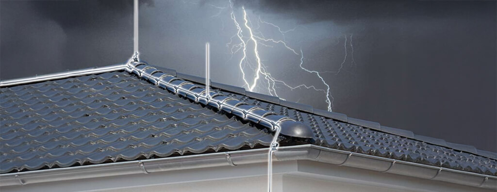
A Lightning Protection System (LPS) is designed to protect structures, people, and internal systems against the direct and indirect effects of lightning strikes.
In this article, we will cover the operating principles of the LPS, highlighting best practices for design, installation, and maintenance to ensure an efficient implementation.
Take a look!
[elementor-template id=”24446″]
What is Lightning Protection (LP)?
Lightning Protection (LP) is the term used to describe the set of technical measures intended to mitigate the risks and impacts arising from lightning strikes on buildings, electrical networks, metallic piping, and other infrastructures exposed to these phenomena.
The need for protection, the economic benefits of installing protective measures, and the selection of appropriate protective measures must be determined through project development.
For practical reasons, the criteria for design, installation, and maintenance of protective measures are considered in two separate groups:
- Lightning Protection System (LPS);
- Surge Protection Measures (SPM);
How Does an LPS Work?
A Lightning Protection System (LPS) is an integrated system of components and measures designed to conduct and dissipate lightning current safely, minimizing the risk of thermomechanical damage, fires, and structural impairment to buildings and installations.
This system is based on a set of Engineering standards and practices that guide the installation, organization, and maintenance of its components.
LPS Technical Standards
Lightning protection is an extremely important issue worldwide, and for this reason, several standards and regulations have been established both nationally and internationally to ensure the safety of buildings and people.
Compliance with standards and regulations related to the LPS is essential to ensure the effectiveness of the lightning protection system.
In addition, compliance with standards is often a legal requirement in many countries and jurisdictions.
Failure to comply with standards may result in legal penalties, in addition to possible issues with insurance companies in the event of incidents.
Among the main relevant standards are:
- NBR 5419-1 – Protection against Lightning – General Principles
- NBR 5419-2 – Protection against Lightning – Risk Management
- NBR 5419-3 – Protection against Lightning – Physical Damage to Structures and Life Hazard
- NBR 5419-4 – Protection against Lightning – Electrical and Electronic Systems within Structures
- IEC 62305-1 – Protection against lightning – General principles
- IEC 62305-2 – Protection against lightning – Risk management
- IEC 62305-3 – Protection against lightning – Physical damage to structures and life hazard
- IEC 62305-4 – Protection against lightning – Electrical and electronic systems within structures
- NFPA 780 – Standard for the Installation of Lightning Protection Systems
Following standards ensures that the design, installation, and maintenance of the LPS are carried out properly and reliably.
Non-compliance with standards can lead to inefficient systems, increasing the risk of lightning-related damage and endangering people and property.
Therefore, to ensure maximum lightning protection and the safety of buildings and occupants, it is essential that LPS design, installation, and maintenance be carried out by specialized professionals in accordance with applicable standards and regulations.
This will ensure the effectiveness of the protection system and significantly reduce the risks associated with lightning strikes.

The technical standards establish that an LPS is made up of two protection systems:
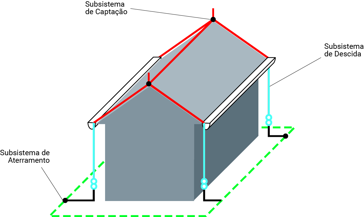
External System
The external LPS is designed to “intercept” lightning discharges and conduct their electrical current to earth.
This system consists of 3 subsystems:
- Air-Termination Subsystem;
- Down-Conductor Subsystem;
- Grounding Subsystem;
Air-Termination Subsystem
The air-termination subsystem has the primary function of intercepting direct strikes, preventing lightning from hitting the protected structure or building in an uncontrolled manner.
Proper sizing allows it to reduce the effects of lightning current in a controlled way, directing it to the down-conductor and grounding subsystems.
The air-termination subsystem may be composed of the following elements, which can be combined according to project needs:
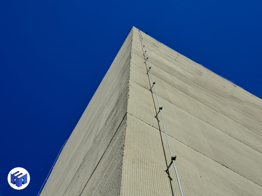
The positioning of air terminals must prioritize the protection of corners, edges, and ridges of the structure, since these points are more susceptible to direct lightning strikes.
This includes installing air terminals at roof edges and protecting upper facade areas and protruding elements.
The standards establish three methods for defining the geometric arrangement of air termination:
- Rolling Sphere Method;
- Protection Angle Method;
- Mesh Method;
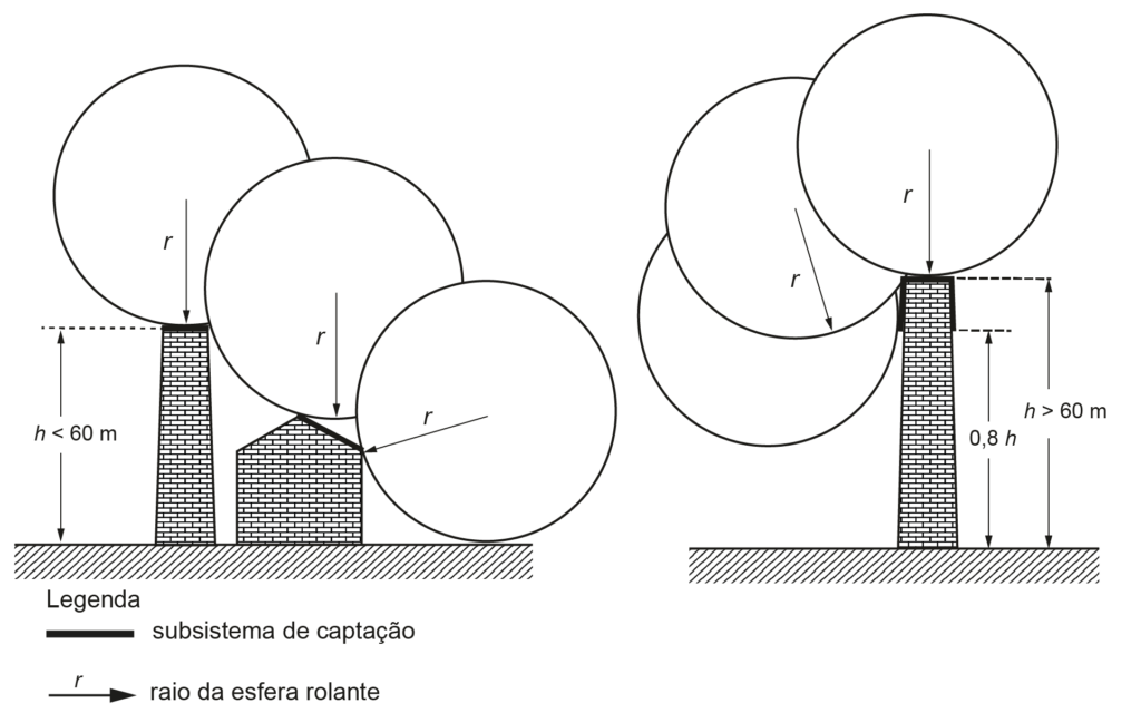
Rolling Sphere Method
The rolling sphere method is the universal methodology for sizing lightning protection systems (LPS), recommended for structures with complex geometries.
It is based on the concept of a theoretical sphere with a specific radius that “rolls” over the structure to be protected.
The points where the sphere touches the building indicate locations susceptible to direct strikes, requiring the installation of air terminals at those points.
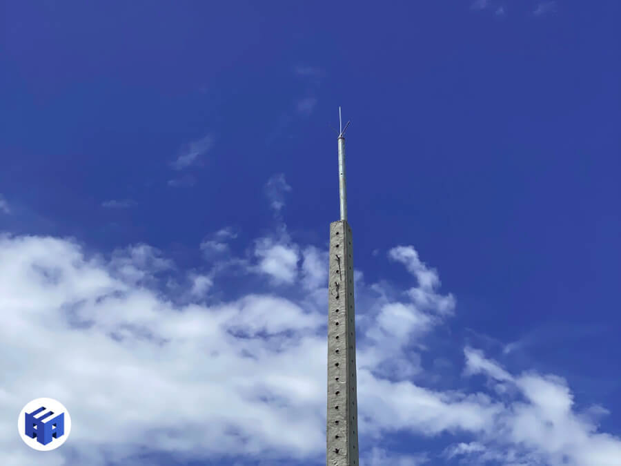
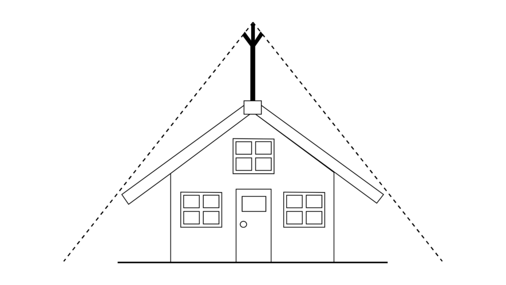
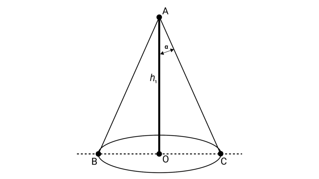
Protection Angle Method (Franklin Rod)
The Protection Angle Method defines a conical protection zone from an air terminal (rod or conductor).
The method establishes an angle (α) between the top of the air terminal and the base of the protected area, within which the structure is theoretically protected against direct strikes.
This method is suitable for simple-geometry structures, such as low-rise buildings or isolated elements (e.g. masts and towers).
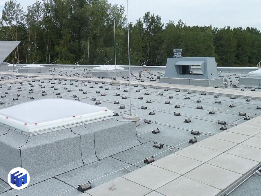
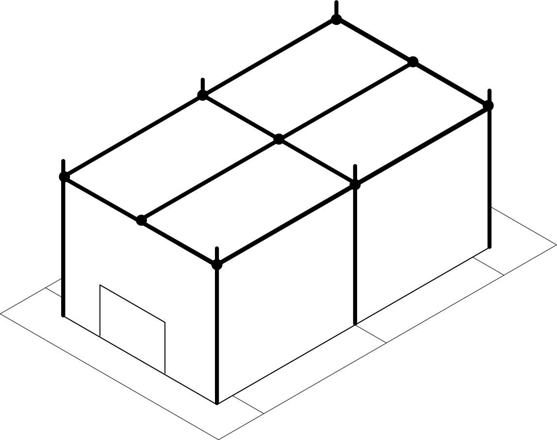
Mesh Method (Faraday Cage)
The Mesh Method uses a network of interconnected horizontal conductors, forming a mesh over the surface of the structure to be protected.
This method is suitable for flat or low-slope roofs, such as commercial buildings, industrial warehouses, and large structures.
The mesh acts as an equipotential barrier, intercepting lightning discharges and directing the current to the down-conductor and grounding system.
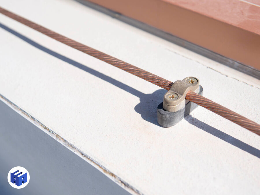
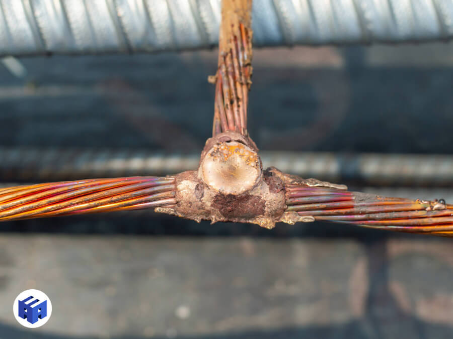
Down-Conductor Subsystem
The down-conductor subsystem is responsible for conducting the lightning discharge current, intercepted by the air terminals, to the grounding system, minimizing the risk of heating, explosions, or dangerous potential differences.
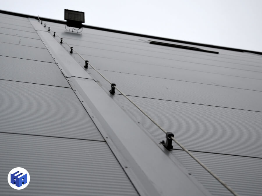
Made up of vertical or horizontal conductors, it must ensure low-impedance paths and balanced current distribution.
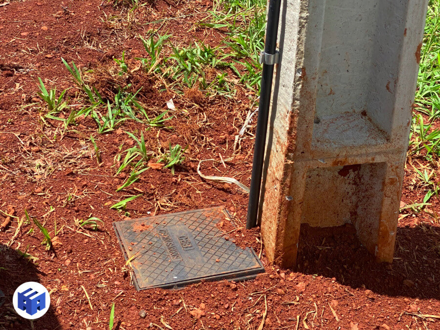
Grounding Subsystem
The grounding subsystem is responsible for safely dissipating lightning discharge current into the soil, limiting step and touch voltages and ensuring the protection of people, equipment, and structures.
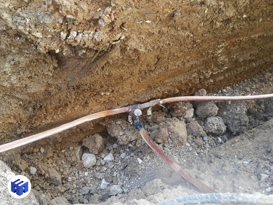

Its design must consider soil characteristics, structural configuration, and integration with the other subsystems (air termination and down conductors).
Internal System
The internal LPS is intended to reduce the risk of dangerous sparking within the protection volume created by the external LPS by using equipotential bonding and safety distances (electrical insulation) between external LPS components and other electrically conductive elements inside the structure
Equipotential Bonding
Connect all metallic parts of the structure (steel framework, piping, grilles, electrical panels) to the LPS conductors
Insulation
Ensure a minimum distance between LPS conductors (e.g. lightning rod down conductors) and other systems (electrical systems, piping, antennas).
Surge Protective Devices (SPD)
LPS Design Project
Developing a proper Lightning Protection System (LPS) design is a critical step in ensuring the system’s effectiveness and reliability. Below are the crucial stages of LPS design and the fundamental considerations for sizing according to specific needs:
Data Collection and Initial Planning
Initial Meetings
Initial meetings are held with the objective of aligning expectations between the technical team and the client.
Physical, operational, and regulatory constraints are identified, along with the required documentation.
Site Survey
The Site Survey consists of a technical visit to carry out a detailed inspection of the place where the LPS will be deployed.
During this visit, the geometric characterization of the building, identification of structural materials, mapping of the surroundings, and assessment of existing systems and electrical infrastructure are performed.
Through this visit, the technical team can anticipate possible issues and adjust project development to the actual site conditions.
Project Development
Based on the collected data, the project development process begins:
Risk Analysis
Based on the collected data, a risk analysis is carried out to determine the level of protection required for the building.
Lightning discharges can cause damage depending on the characteristics of the structure to be protected.
Protection Levels
Four protection levels (PL) against lightning discharges are considered (I to IV).
For each PL, a set of maximum and minimum lightning current parameters is defined.
This classification determines conductor sizing, the thickness of metallic elements, and the capacity of complementary systems such as surge protective devices (SPDs), ensuring the controlled dissipation of residual voltages and electrical currents.
LPS Classes
The characteristics of an LPS are determined by the characteristics of the structure to be protected and by the protection level considered for lightning discharges.
The table shows the four LPS classes (I to IV), which correspond to the lightning protection levels.
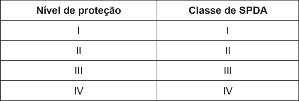
Each LPS class is characterized by the following.
a) Data dependent on the LPS class:
- Maximum and minimum lightning current parameters;
- Rolling sphere radius, mesh size, and protection angle;
- Typical spacing between down conductors and ring conductors;
- Safety distance against dangerous sparking;
- Minimum length of earth electrodes;
b) Factors not dependent on the LPS class:
- Equipotential bonding for lightning protection;
- Minimum thickness of metallic plates or piping in air-termination systems;
- LPS materials and conditions of use;
- Materials, configuration, and minimum dimensions for air terminals, down conductors, and grounding electrodes;
- Minimum dimensions of bonding conductors;
Basic Design
The Basic Design establishes the general parameters and the fundamental technical premises for implementation, defining the air-termination system best suited to the demands of the environment.
The number and spacing of down conductors are defined, as they will be responsible for connecting the air-termination system to the grounding system that dissipates lightning discharges, minimizing the risk of current induction in cables, metallic structures, and other systems.
Calculations are carried out to specify the grounding mesh and surge protection measures (SPM), according to equipment specifications, ensuring the protection and stability of the electrical infrastructure.
Executive Design
The Executive Design consolidates all definitions established in previous phases, transforming them into a set of documents and procedures that guide the practical execution of the Lightning Protection System:
- Technical Descriptive Report;
- Drawings and Diagrams;
- Analytical, Summary, and Consolidated Budget Spreadsheets;
- Technical Responsibility Annotation (ART);
Documentation Delivery
At the end of project development, the client receives all files and records required for the execution and maintenance of the system:
Technical Descriptive Report
The Technical Descriptive Report presents all aspects of the system, such as the technologies adopted, installation methods, reference standards, and testing procedures planned in the design.
This document describes both the technical foundations (“why”) and the practical guidelines (“how”) behind each choice, allowing the client and the teams involved to clearly understand the criteria and parameters that guide the system’s conception and implementation.
Drawings and Diagrams
The development of technical layouts involves creating detailed drawings that represent […]
These layouts include floor plans, sections, and elevations that describe in detail […]
The graphic representations are designed to map the installation of each component with precision […]
The layouts are essential for project communication, guiding the installation team and reducing the margin for error during execution.
In addition to guiding the assembly process, they serve as technical documentation for inspections, maintenance, and future adaptations, functioning as a detailed reference that simplifies interventions and adjustments to the infrastructure, ensuring that the network operates as planned and efficiently over time.
Analytical, Summary, and Consolidated Budget Spreadsheets
The technical budget spreadsheets, prepared at three levels of detail (analytical, summary, and consolidated), allow precise analysis of the costs associated with each project component, covering materials, equipment, labor, and any additional services.
Technical Responsibility Annotation (ART)
The Technical Responsibility Annotation consists of the formal registration of the project with the Regional Council of Engineering and Agronomy (CREA), assigning legal responsibility to the qualified professional who signs it.
This instrument ensures that the project and its execution comply with technical standards and applicable legislation, providing legal backing and validating the competence of the person responsible for the design and implementation of the engineering services.
The ART is a mandatory document and serves as a legal guarantee for the client, confirming that the project was prepared by a qualified professional.
Final Considerations
Brazil is one of the countries with the highest incidence of lightning discharges in the world, recording more than 70 million lightning strikes annually, according to data from the National Institute for Space Research (INPE).
This high frequency of lightning directly affects the safety and integrity of structures and systems and, on average, impacts more than 300 people per year.
The need for effective Lightning Protection (LP) systems is therefore crucial to mitigate the risks associated with these events, ensure operational continuity, and above all protect lives.
In conclusion, the Lightning Protection System (LPS) is an indispensable solution for ensuring the safety of structures, equipment, and people in the face of lightning threats.
The proper installation of the LPS by qualified professionals is crucial to its effectiveness, as is the choice of appropriate materials and the strategic positioning of its components. Through proper air-termination sizing and an efficient grounding system, it is possible to extend protection and minimize the risks of damage caused by electrical discharges.
Do not wait! Secure the safety of your structures and equipment with our specialized Lightning Protection System services. Contact us!
References
CREA (Regional Council of Engineering and Agronomy) – “CREA recommends hiring an Electrical Engineer for LPS installation“
ABNT (Brazilian Association of Technical Standards) – “NBR 5419 – Protection against Lightning”
DEHN – “Lightning Protection Guide 3rd Edition”
INPE (National Institute for Space Research) – “Two-Year Map”
Frequently Asked Questions
What is an LPS?
The LPS (Lightning Protection System) is an integrated system made up of air terminals (rods, meshes, or interception devices), down conductors, grounding, and equipotential bonding, designed to safely conduct lightning currents to the ground, protecting structures, people, and equipment against direct and indirect damage, as established in ABNT NBR 5419.
When is an LPS mandatory?
The requirement for an LPS is determined by the risk analysis defined in NBR 5419, considering factors such as building height (above 30 meters), geographic location (high lightning density), and the presence of flammable materials or critical structures (hospitals, chemical plants, data centers).
What is the difference between a lightning rod and an LPS?
A lightning rod refers specifically to the air terminals that intercept the lightning discharge. The LPS, on the other hand, encompasses the entire system, including air terminals, down conductors, grounding, and equipotential bonding measures, ensuring the safe dissipation of lightning current.
What are the methods of lightning protection?
The methods standardized by NBR 5419 include the Franklin Method (pointed air terminals), the Faraday Cage (peripheral conductive mesh), the Protection Angle Method (definition of geometric protection zones), and ESE systems (Early Streamer Emission devices), which use ionization for early lightning interception.
How much does an LPS service cost?
The implementation cost of a Lightning Protection System (LPS) is influenced by technical variables such as structural complexity, the selected protection methodology, material specifications, and local conditions.