Understand what the physical network layer is, its components, the most common failures, certification tests, and the specialised services required for reliable infrastructure.
Check it out!
Introduction
The Physical Network, or the physical layer of the network, is the medium (cables) through which data packets are transmitted in a communication network.
This layer deals exclusively with the electrical, optical, or electromagnetic aspects of communication and involves converting binary data into physical signals that can be transmitted through the communication medium, whether that is copper cabling, optical fibre, or wireless connection.
In addition, the physical layer also specifies how devices connect physically (such as plugs, cables, and connector standards).
Any failure or inadequacy in this layer may result in degraded performance, interference, or even complete network interruption.
In this article, we will address the main issues that affect the physical network and impair its performance, and we will suggest specialised services that can help solve these issues while indicating the procedures needed to bring the network into compliance.
[elementor-template id=”24446″]
Main Components of the Physical Network Layer:
The components of a network’s physical layer are responsible for ensuring signal transmission between devices. These components can be divided into hardware categories and transmission media.
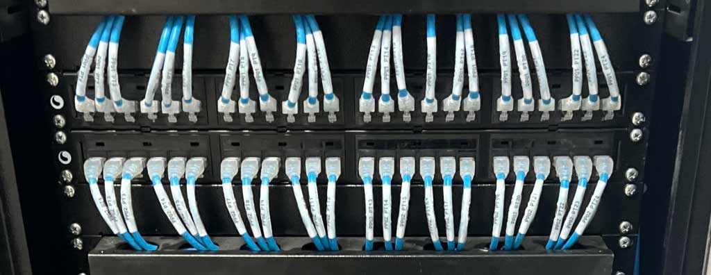
A3A Engenharia de Sistemas Collection
1. Transmission Media
- Copper Cables: Twisted-pair wires (such as CAT5e, CAT6) used to transmit electrical signals.
- Optical Fibre: Uses light pulses to transmit data and is immune to electromagnetic interference.
- Wireless Media: Electromagnetic signals transmitted through the air (such as Wi-Fi and Bluetooth).
2. Connectors
- RJ-45 Connectors: Used in Ethernet networks to connect twisted-pair cables.
- Optical Fibre Connectors: Connectors such as SC, LC, and ST that interconnect fibre cables.
- BNC Connectors: Used in coaxial cables for video transmission or in some legacy networks.
3. Interconnection Devices
- Repeaters: Amplify the signal to cover longer distances.
- Hub: Distributes the electrical or optical signal from one port to all other ports in a local area network (LAN) environment.
- Transceivers: Convert electrical signals into optical signals and vice versa, enabling data transmission through different types of physical media.
4. Modulation and Encoding
- Modulators/Demodulators: Perform signal modulation and demodulation, converting digital data into analogue signals for transmission and back again.
- Encoding Schemes: Techniques such as Manchester or 8b/10b that determine how binary data will be physically represented on the medium.
5. Signalling Standards
- Frequency and Voltage Specifications: Define signal amplitude and the frequency of transmitted electromagnetic waves.
- Synchronization: Ensures that both the sender and the receiver remain synchronised so that received signals are interpreted correctly.
Most Common Problems in the Physical Layer
Damaged or Poorly Connected Cables
- Symptoms: Intermittent communication interruptions, low data transfer rates, or complete lack of connection.
- Causes: Mechanical wear of the cables, accidental cuts, loose terminations (patch panels, keystones), or problems in horizontal cabling.
- Solution: Initial diagnosis involves visual inspection of cables and tests using cable certifiers that verify continuity and cabling integrity. Replacing damaged or inadequate cables is crucial, followed by detailed network certification after repairs.
Electromagnetic Interference (EMI)
- Symptoms: Packet loss, transmission errors, and poor performance, especially in environments with a high density of electrical equipment.
- Causes: Network cables installed close to interference sources, such as electric motors, lighting systems, or other high-power cabling.
- Solution: The physical network should be mapped to identify points susceptible to interference. A proper solution involves moving the cabling away from EMI sources or using shielded cables (STP) to minimise interference effects.
Improper Patch Cord Installation
- Symptoms: Intermittent drops in connectivity and reduced network quality in areas with a high concentration of devices.
- Causes: Patch cords that are too long, poorly terminated, or improperly tensioned.
- Solution: The remediation process involves reviewing installation standards and replacing the patch cords.
Connectivity Problems in Switches and Routers
- Symptoms: Intermittent connections, network slowness, or devices that cannot communicate.
- Causes: Poorly established connections, damaged switch ports, or overheating of the equipment.
- Solution: Diagnosis involves checking connectors, verifying device condition, and analysing network equipment logs. Replacing damaged ports and correctly configuring switches eliminates these bottlenecks. Continuous monitoring of network infrastructure is also recommended to prevent new issues from arising.
Component Degradation Over Time
- Symptoms: Slow but constant degradation in network performance, with an increase in transmission error rates.
- Causes: Ageing components, oxidised connectors, and physical wear of the cabling.
- Solution: Periodic replacement of physical network components is recommended, along with preventive maintenance. A scheduled maintenance plan, combined with updating network materials and devices, ensures greater longevity and better performance.
Diagnosis and Resolution of Problems
1. Initial Diagnosis
- Symptom Survey: The first stage involves gathering the issues reported by users, such as slowness, drops, or lack of connection.
- Analysis of Equipment and Cables: With the aid of specialised tools, signal quality and possible interference sources are analysed.
2. Testing and Certification
- Use of Testing Equipment: Continuity testing, network-point certification, and transfer-rate analysis are essential to identify physical problems in the infrastructure.
Certification tests in structured cabling are essential to ensure that network infrastructure meets the performance and quality standards established by norms such as TIA/EIA-568 and ISO/IEC 11801.
During these tests, a variety of issues can be detected, affecting the network’s efficiency and reliability.
Below, we detail the most common issues identified:
1. Wire Map Errors
- Definition: Verifies whether wire pairs are correctly connected at both ends of the cable.
- Detected Problems:
- Reversals: When the wire pair is reversed between cable ends.
- Open: A wire is not connected at one or both ends.
- Short: Two or more wires are in contact, creating a short circuit.
- Miswires: Wires connected to the wrong pins.
- Split Pairs: Correct wires on the correct pins, but incorrect pairs used, affecting impedance and crosstalk.
2. Excessive Attenuation
- Definition: Loss of signal strength as it travels through the cable.
- Detected Problems:
- High Attenuation: May be caused by overly long cabling, poorly made connections, or low-quality cables.
- Defective Connectors: Poor installation or low-quality components that increase signal loss.
3. Near-End Crosstalk (NEXT)
- Definition: Electrical interference between nearby wire pairs at the same end of the cable.
- Detected Problems:
- High NEXT: Indicates that the signal in one pair is interfering with another pair, reducing transmission quality.
- Common Causes: Untwisted pairs, excessive cable stripping, poor termination, or excessive proximity between pairs.
4. Far-End Crosstalk (FEXT)
- Definition: Interference between wire pairs measured at the opposite end of the cable.
- Detected Problems:
- High FEXT: Similar to NEXT, but measured at the far end; it may affect signal integrity.
5. Power Sum NEXT (PSNEXT)
- Definition: Cumulative measurement of the crosstalk that each pair suffers from all the other pairs.
- Detected Problems:
- High PSNEXT: Indicates that multiple pairs are interfering simultaneously with a specific pair, worsening crosstalk.
6. Return Loss
- Definition: Quantifies reflection of the signal back to the source due to impedance discontinuities.
- Detected Problems:
- High Return Loss: May be caused by poor connections, physical cable damage, or impedance inconsistencies.
- Impact: Affects the receiver’s ability to distinguish the original signal from reflections, reducing transmission quality.
7. Propagation Delay
- Definition: The time it takes for the signal to travel the length of the cable.
- Detected Problems:
- Excessive Delay: May indicate cables longer than permitted or issues with cable quality.
- Impact: Can cause synchronisation problems in protocols that depend on precise timing.
8. Delay Skew
- Definition: The difference in propagation time between the fastest and slowest pairs.
- Detected Problems:
- High Delay Skew: May result from cable construction variations or physical damage.
- Impact: Affects synchronised arrival of signals, which is essential for applications such as Gigabit Ethernet.
9. Alien Crosstalk
- Definition: Interference between different adjacent cables, not only between pairs within the same cable.
- Detected Problems:
- Alien NEXT and Alien FEXT: Interference from neighbouring cables, especially in high-density cabling environments.
- Impact: May seriously degrade performance in high-speed applications such as 10 Gigabit Ethernet.
10. Excessive Length
- Definition: Verifies whether the cable length is within the limits specified by standards.
- Detected Problems:
- Overlong Cable: Cables exceeding the maximum permitted length (generally 100 metres for Ethernet).
- Impact: Increases attenuation and propagation delay, compromising signal integrity.
11. Inconsistent Impedance
- Definition: Variance in impedance along the cable, which should remain consistent to avoid reflections.
- Detected Problems:
- Impedance Discontinuities: Due to poor connections, damaged cables, or low-quality components.
- Impact: Causes return loss and may affect overall network performance.
12. Shield Integrity Problems
- Definition: Evaluates continuity and effectiveness of shielding in shielded cables (STP, FTP).
- Detected Problems:
- Broken or Inadequate Shielding: May result in greater susceptibility to electromagnetic interference (EMI).
- Impact: Increases signal noise, reducing communication quality.
13. Poorly Made Connections
- Definition: Problems in cable termination at connectors, patch panels, or outlets.
- Detected Problems:
- Unbalanced Pairs: Excessive stripping or untwisting of conductors near the connectors.
- Loose or Oxidised Terminations: May cause intermittence or total loss of connection.
14. Degradation Due to Temperature and Environment
- Definition: Evaluates the impact of adverse environmental conditions on cabling performance.
- Detected Problems:
- Exposure to Excessive Heat: May deteriorate cable insulation.
- Moisture or Water: May cause corrosion or shorts in the cabling.
- Impact: Reduces cabling service life and can lead to unexpected failures.
15. External Electromagnetic Interference
- Definition: Evaluates cable susceptibility to interference from external sources, such as electrical equipment.
- Detected Problems:
- Proximity to EMI Sources: Cables installed close to motors, fluorescent lamps, or other electrical wiring.
- Impact: Increases signal noise, resulting in data loss or reduced speed.
Importance of Detecting and Correcting These Problems
Detecting these issues during certification tests is crucial to ensure that network infrastructure will provide reliable performance and be prepared to support current and future applications. Unidentified problems may lead to:
- Performance Degradation: Reduced transmission speeds, increasing file transfer time and affecting real-time applications.
- Network Instability: Intermittent connections that affect user productivity.
- Higher Maintenance Costs: Unresolved problems may worsen, requiring more expensive repairs in the future.
- Security Risk: Network failures may expose vulnerabilities that can be exploited.
Correction and Remediation
- Replacement and Repair: After diagnosis, damaged or inadequate cables, connectors, and equipment are replaced.
- Infrastructure Remediation: Physical infrastructure is corrected, including cable repositioning, rack reorganisation, and fixes related to the physical installation.
Specialised Services
To ensure the full operation and performance of the physical network, it is essential to rely on a team specialised in computer networks.
A3A Engenharia offers the following services:
- Complete Diagnosis of Physical Infrastructure: Identification of faults, interference, and cabling remediation;
- Mapping of Network Points: Identification of points in installations that do not have network records and documentation;
- Rack Organisation: Cabling organisation, point identification, and patch panel reinstallation;
- Network Certification: Full certification of the infrastructure, ensuring compliance with quality standards;
- Infrastructure Remediation and Repair: Solutions that correct performance problems by replacing and adapting cables and equipment;
- Preventive Maintenance: Implementation of ongoing maintenance plans, including network monitoring and scheduled component replacement;
- Issuance of Reports: Reports on the services performed;
Conclusion
The physical layer of a computer network is the foundation of all communication performance. Problems such as damaged cables, electromagnetic interference, and inadequate connectors are common, but they can be easily solved with accurate diagnosis and specialised services. Proper infrastructure ensures high performance and reliability in data traffic.
Certification tests in structured cabling are fundamental for identifying and correcting problems that may compromise network efficiency and reliability. Early detection of these issues enables corrective action that ensures optimal performance of the network infrastructure, supporting current and future communication and data-transfer demands.
Complementary Articles:
Check out a few articles that can help you better understand the challenges of a communication network:
Shielded Network Cable – Industrial Networks
Network Design: The Definitive Guide to Planning, Implementing, and Managing Network Infrastructures
NBR 14565: Structured Cabling for Commercial Buildings
Structured Cabling: Why Hire a Structured Cabling Design Project?
Normative References:
1. ANSI/TIA-568
- Telecommunications Cabling Standard: Defines the requirements for the design and installation of structured cabling systems in commercial buildings, including specifications for twisted-pair cabling, optical fibre, and recommended installation methods.
2. ISO/IEC 11801
- Generic Cabling for Customer Premises: This international standard defines structured cabling patterns to support a wide range of network applications, covering both copper cabling and optical fibre, and specifying distances and performance requirements for different network topologies.
3. IEEE 802.3
- Ethernet: Defines Ethernet communication standards, including specifications for transmission rates, network topologies, and signal-encoding methods for copper and optical fibre cabling. It includes standards such as 10BASE-T, 100BASE-TX (Fast Ethernet), and 1000BASE-T (Gigabit Ethernet).
4. IEEE 802.11
- Wireless Network Standard (Wi-Fi): Defines standards for wireless local networks, establishing operating requirements for different frequencies and speeds while ensuring interoperability and security of wireless networks in corporate and residential environments.
5. ANSI/TIA-606
- Administration of Telecommunications Infrastructure: This standard specifies requirements for documentation and labelling of network infrastructure, ensuring efficient management of cabling, racks, and devices.
6. ANSI/TIA-942
- Data Centers: Defines best practices for the design and construction of data centres, with a focus on cabling infrastructure, power, and resilience. It also addresses issues such as redundancy and scalability.
7. BICSI 002
- Data Center Design Practices: An internationally recognised guide for data centre design and construction, complementing ANSI/TIA-942 with specific guidelines for layouts, cooling, and cabling.
8. TIA-569
- Standard for Telecommunications Pathways and Spaces: Establishes design and installation requirements for physical infrastructure such as ducts, conduits, and telecommunications rooms that support structured cabling.
9. ABNT NBR 14565
- Cabling Systems for Commercial Buildings: A Brazilian standard that defines requirements for implementing structured cabling in commercial environments, from material selection to installation procedures.
Final Considerations:
To ensure that your physical network is operating under the best possible conditions, it is necessary for the network infrastructure, especially the structured cabling, to be in the best possible condition. For that reason, it is important to rely on the services of a specialised engineering company that has the expertise and tools required to perform a complete diagnosis and propose effective solutions.
Ensure performance in your network with specialised services!
We offer diagnostic services, complete testing, and performance reports for network points, as well as personalised consulting to adapt the infrastructure to your needs.

A3A Engenharia de Sistemas has a large technical portfolio and numerous success cases in structured cabling projects.
Get in touch and speak with our Engineering department.