Structured cabling in industrial environments represents one of the greatest challenges for infrastructure and technology professionals. Unlike conventional corporate environments, factories and industrial plants require specific technical solutions to mitigate the effects of interference, harsh conditions, and stringent regulatory requirements. Understanding these particularities is essential to ensure secure, efficient networks prepared for the growing demands […]
Check it out!
Structured cabling in industrial environments represents one of the greatest challenges for infrastructure and technology professionals. Unlike conventional corporate environments, factories and industrial plants require specific technical solutions to mitigate the effects of interference, harsh conditions, and stringent regulatory requirements. Understanding these particularities is essential to ensure secure, efficient networks prepared for the growing demands of automation and connected industry.
In this article, a comprehensive guide on structured cabling for industries will be presented, covering adopted international standards, essential technical tips for implementation, specific precautions for aggressive environments, and relevant technological trends for long-term projects. The goal is to provide insights that support specification, execution, maintenance, and evolution of industrial cabling infrastructure, aligning robustness, performance, and compliance with normative references.
Check it out!
[elementor-template id=”24446″]
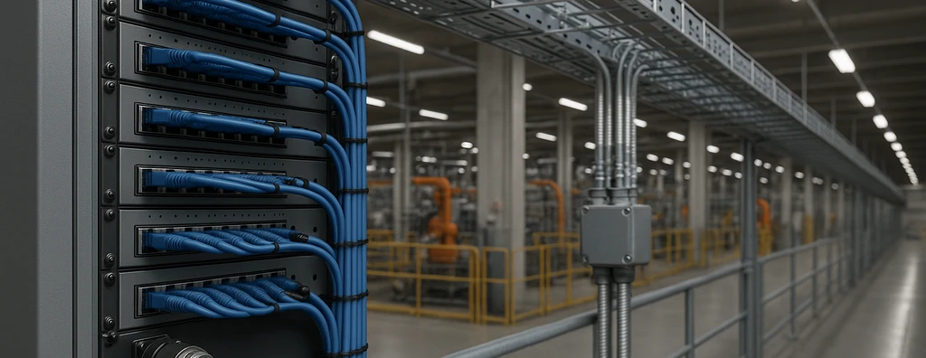
In industrial environments, structured cabling adopts differentiated principles regarding topology, material selection, and physical architecture compared to traditional corporate environments. The system must be designed to support high data transmission loads, integrate with process control systems, automation, sensors, and security devices, as well as allow for future expansions and adaptations.
Industrial Network Architecture
It is essential to perform detailed mapping of connection points, evaluate coexistence with power electrical systems, plan protected routes to prevent mechanical damage, and ensure accessibility for inspection and maintenance.
Regulatory Compliance
Regulatory compliance is the foundation for industrial projects. The main references for industrial structured cabling include:
- ANSI/TIA-568: Specifies criteria for twisted pair cables (UTP, STP), fiber optics, topologies, and performance in horizontal and backbone cabling.
- TIA/EIA-569-C: Defines physical pathways, ducts, shafts, outlet positions, and standards for technical rooms.
- ANSI/TIA-1005: Establishes specific requirements for industrial environments, covering protection ratings, resistance to chemical agents, vibration, and electromagnetic noise.
- ISO/IEC 11801: International standard for generic cabling in customer premises, with emphasis on interoperability and channel classes.
Strict alignment with the scope of these standards ensures interoperability, performance, and systemic robustness, as well as facilitating acceptance in audits and industrial certifications.
Industrial Structured Cabling: Key Elements
The industrial structured cabling system typically consists of the following elements:
- Consolidation Points: Areas for cable unification, derivation, and rearrangement.
- Vertical Backbone: Spans buildings, connecting main and intermediate technical rooms with fiber optics or industrial-grade copper cables.
- Horizontal Cabling: Interconnects the intermediate cross-connect with work areas, using UTP, STP, or fiber optic cables, as categorized in ANSI/TIA-568-C.2.
- Patch Panels and Racks: Organize distribution and facilitate testing/maintenance.
- Industrial Telecommunication Outlets: Designed for mechanical resistance, sealed contacts, and high durability.
Project Requirements
During the project phase, the definition of horizontal lengths should not exceed 90 meters for permanent links, while complete channels, including patch cords, total up to 100 meters, respecting international standard margins.
Although the standard establishes a 90-meter limit for the permanent link and up to 100 meters for the complete channel (including patch cords), it is recommended that the project prioritize the strategic location of edge racks and consolidation points. The objective should always be to minimize horizontal cabling run lengths, seeking shorter and more direct paths.
In practice, when most of the points served by an edge rack are very close to the maximum allowed limit, this indicates that the rack position may not be optimized for the plant layout. This scenario can lead to “stretched” cabling, with little margin for rearrangements, layout changes, or future expansions.
Project best practices include:
- Evaluate the coverage radius of each edge rack, centering it relative to the highest concentration of points.
- Avoid installing racks at extremities or locations where most cables would need to travel distances near the normative limit.
- Plan intermediate consolidation points in extensive areas or those with architectural barriers, facilitating expansions and maintenance.
- Pre-map critical areas (auditoriums, technical rooms, data centers), designing alternative routes and physical redundancy when applicable.
In addition to ensuring compliance with international standards (NBR 14565, ISO/IEC 11801), this approach adds flexibility, organization, and scalability to the network infrastructure, reducing costs of future interventions and increasing system lifespan.
Expert tip
When defining rack positions and planning cabling, it is possible to use heat maps to identify regions with high point density. This helps avoid overloading a single rack and facilitates infrastructure segmentation, aligning performance and ease of maintenance.
When I refer to a “heat map” in the context of structured cabling design, I am referring to a visual tool used to graphically represent the density of network points distributed across the environment’s floor plan. It is not about temperature, but about concentration zones of outlets, devices, or equipment that will require connectivity.
In practice, during the project survey, we mark on the floor plan drawing the locations of each planned network point. Using CAD, Revit, or even spreadsheet resources, we apply a color scale: areas with many points receive “warm” colors (red, orange), areas with few points, “cool” colors (blue, green).
This mapping makes it easier to visualize where the greatest demands are, helping in defining the best location for edge racks. The objective is to position the rack so that it sits at the “center of gravity” of these most critical areas, reducing average cable lengths and balancing distribution.
The use of this type of analysis:
- Prevents undersizing the rack in critical zones.
- Facilitates future expansions, as it already considers capacity reserves.
- Reduces costs and infrastructure complexity (cable trays, ducts).
- Makes the project more organized and predictable in the field.
For those who do not use CAD tools, it is possible to simulate this process with point overlay on prints or even Excel spreadsheets, creating a visual representation of density.
I recommend adopting this method early in the project phase to increase assertiveness in defining racks and cabling routes.

Cable Type Selection
The correct choice of cables is very important to ensure performance and robustness. In industry, the main options are:
- Shielded Twisted Pair Cable (STP): Recommended for areas with high electromagnetic interference. Its individual and/or overall shielding mitigates intense industrial noise.
- UTP Category 6/6A and Higher Cable: Applicable in relatively protected environments or within technical areas, ideal for Ethernet up to 10 Gbps.
- Multimode and Singlemode Fiber Optic: Essential for long interconnections, backbone, and areas subject to discharges or environments with high EMI.
- Flame-Retardant and Oil-Resistant Jacketed Cables: Required in hazardous locations, preventing fire propagation and chemical agent action.
- Hybrid Cables: Integrate fiber optics and metallic conductors for power and data applications in a single enclosure.
Cables must be selected according to environmental requirements, protection class (IP), chemical resistance, temperature, abrasion, and specific safety certifications for the industrial segment in question.
The physical architecture of industrial structured cabling typically adopts the star topology, allowing fault isolation and easy management. However, hybrid variants may be used, especially in legacy systems.
Key Topology Considerations
- Distribution centers (Main Distribution Frames) located in protected areas;
- Secondary distribution rooms (Intermediate Distribution Frames) strategically distributed to cover distances;
- Optical backbones interconnecting buildings, warehouses, and manufacturing areas;
- Physical distribution routes planned to avoid areas of high mechanical or electrical risk;
- Use of shafts, shielded ducts, suspended trays, and hermetic channels for cable pathways.
Protection elements, such as cable glands, anchoring, and durable identification labels, must be planned to facilitate identification, inspection, and maintenance of assets.
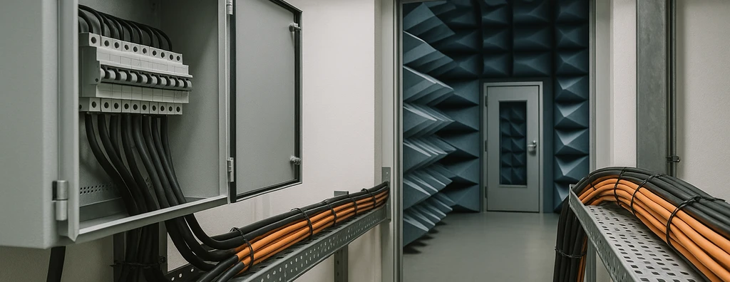
In the industrial environment, cabling is subject to specific risks: electrical noise, vibration, moisture, high temperatures, chemical agents, conductive dust, and abrasion.
- Shielding: Use of STP cables, fiber optics, and grounded metallic connectors significantly reduces EMI and radiated disturbances.
- Protected routes: Metallic ducts, sealed cable trays, and physical segregation of power circuits are recommended practices.
- Interference Protection: Minimum separation according to TIA/EIA-569-C between telecommunications cabling and power cables.
- Physical redundancy: Alternative channels for mission-critical applications, avoiding single points of failure.
- Labeling and traceability: Labels resistant to oil, water, and abrasion for tracking cables and critical connections.
All these factors increase systemic availability and contribute to predictive and corrective maintenance.
Electromagnetic Compatibility
In industrial environments, the presence of intense sources of electromagnetic interference (EMI) represents one of the greatest challenges for the integrity and performance of structured cabling systems. Equipment such as motors, inverters, power panels, and welding systems are just a few examples of devices capable of generating noise that affects data transmission and can compromise the entire network communication.
Electromagnetic interference (EMI), is a risk factor that can impair the performance and reliability of the Network, increase error rates, and even lead to signal loss at critical points. Therefore, reducing or mitigating the effects of EMI is essential to ensure the stability and success of the project.
Best practices to minimize EMI risks in industrial cabling:
- Use of shielded cables (FTP/STP) and appropriate connectors.
- Proper equipotential bonding and grounding throughout the infrastructure.
- Physical separation and distancing between data cables and power cables.
- Preference for grounded metallic cable trays, functioning as a noise barrier.
- Crossing data and power cables at 90° angles, avoiding prolonged parallel paths.
Note: Due to the technical complexity present in industrial environments, it is highly recommended to hire a company specialized in equipotential bonding, electromagnetic compatibility, and structured cabling projects. Qualified professionals will analyze the scenario, propose customized solutions, and apply the best normative practices (NBR 5410, NBR 5419, NBR 14565, IEC 61000, among others), ensuring system integrity.
Electromagnetic compatibility is fundamental in industrial environments — understand the technical details in our specialized article.
Installation Standards
Proper installation directly influences the lifecycle and operational availability of the system. The following criteria must be followed:
- Compliance with minimum cable bend radius: Prevents attenuation and shielding damage;
- Organization in trays, channels, and racks: Maximizes airflow, facilitates maintenance, and reduces risks of physical damage;
- Secure fastening: Use of industrial ties and anti-vibration supports in critical areas;
- Attention to terminations: Use of proper tools, avoiding contact failures and performance loss;
- Cable segregation by type and function: Clear differentiation between data, control, voice, and video, improving performance and traceability.
The use of patch panels facilitates maneuvers for rearrangement, testing, and rapid identification of anomalies.
Documentation
Every installation must be documented with logical and physical diagrams, covering origin points, destinations, pathways, and numerical route identification.
After installation, performing functional tests and certification is mandatory, validating compliance with normative parameters:
- Continuity, attenuation, NEXT, and return loss tests for metallic cables;
- Optical loss, OTDR, and splice inspection tests for fiber optics;
- Physical and logical mapping of all terminations;
- Photographic documentation of critical interconnections and standardized visual identification;
- Creation of a predictive maintenance plan, with periodic inspection, cable lifecycle curve analysis, mechanical integrity verification, and record updates.
- As-Built with photos
Periodic certification, according to ANSI/TIA-568 and TIA-1005 criteria, validates operational continuity, reduces unplanned failures, and meets quality requirements for audits and certified industrial processes.
Key Trends
With Industry 4.0 and the growing demand for convergent OT-IT networks, industrial structured cabling needs to anticipate trends and absorb new technologies:
- Implementation of Cat 6A/7/8 for ultra-high-speed Ethernet;
- Expanded use of fiber optics tolerant to the industrial environment (with reinforced anti-abrasion and flame-retardant coatings);
- Hybrid cabling for power and data (Industrial Power over Ethernet, IEEE 802.3bt);
- Native integration with industrial IoT: Provision of dedicated access points, including connectivity for sensors, actuators, and smart devices;
- Automated route monitoring: Remote diagnostic solutions and sensors integrated into cabling for early fault detection;
- Adoption of RFID labeling systems for real-time link inventory and tracking;
- Compatibility with industrial wireless networks: Cabling to support robust industrial wireless access points, including dedicated optical backhaul.
These trends guide investments in retrofit, expansion planning, and new projects, promoting alignment with the demands of digitalization, information security, and operational resilience required in modern industry.
Structured cabling in industrial environments requires technical approaches that overcome typical challenges of production environments, including exposure to noise, mechanical risks, chemical agents, and accelerated expansion dynamics. Adherence to international standards, adoption of the best design and installation criteria, as well as preparation for trends such as Industrial Ethernet, Industrial PoE, and high-resilience fiber optics, ensures maximum availability, flexibility, and scalability for connectivity infrastructure.
The correct integration between logical and physical architecture, combined with certification and predictive maintenance processes, results in systems oriented toward operational longevity and high performance. It is the responsibility of systems engineering to act judiciously in the definition, implementation, and evolution of these critical assets, consolidating the foundation that enables digital transformation, advanced automation, and the high standards of industrial productivity.
We thank you for reading this technical guide on structured cabling for industrial environments. For updates, exclusive content, and industry news, follow A3A Systems Engineering on social media and stay ahead in best practices of applied technology and engineering.
Also read:
Grounding and Equipotential Bonding
Electromagnetic Compatibility in Electrical Projects: Hidden Risks and Technical Recommendations
Industrial Networks: Requirements, Protocols, and Integration with SCADA Systems
Frequently Asked Questions
1. What differentiates industrial structured cabling from conventional corporate cabling?
The industrial environment presents greater electromagnetic interference, extreme temperatures, vibrations, and exposure to chemical agents. Therefore, it requires more robust materials and construction methods, efficient grounding, and often specific certifications to ensure network reliability and safety.
2. Which technical standards are mandatory for cabling projects in industrial environments in Brazil?
Projects must follow NBR 14565 and international references such as ANSI/TIA-1005, as well as consider electrical safety standards (NBR 5410), electromagnetic compatibility, and standards specific to each industry (food, automotive, etc.).
3. What are the best practices to avoid interference (EMI) in industrial networks?
Using shielded cables (STP/FTP), grounded metallic cable trays and ducts, separating power and data paths, maintaining minimum distances from noise sources, and adopting functional grounding techniques are essential to minimize EMI.
4. Is fiber optic cabling recommended for industrial environments?
Yes. Fiber optics is immune to electromagnetic interference and ideal for long distances and environments with noise, high humidity, or spark risks. It is common to combine metallic cabling for controlled areas and fiber optics for industrial backbones.
5. What is the importance of testing and certifying cabling after installation?
Testing and certifying ensures that the system achieves the performance specified by standards. This prevents failures, reduces rework, and ensures infrastructure longevity. The certification report is also a differentiator in audits and contracts.
6. How to plan for future expansions in industrial environments?
Reserve space in ducts and cable trays, adopt modular racks, specify cable categories above the current minimum, and thoroughly document the entire infrastructure. This way, future expansions can be made with minimal operational impact.
7. What trends are currently impacting industrial cabling?
The advancement of IIoT (Industrial Internet of Things), 10G/40G industrial networks, high-power PoE, advanced automation, and intelligent monitoring systems require compatible cables, connectors, and methodologies, as well as projects designed for flexibility and constant upgrading.
8. What is the relevance of functional grounding in industrial networks?
Functional grounding protects equipment, minimizes noise, and contributes to data integrity. It must be sized according to standards and integrated into the project from the beginning, avoiding improvised adaptations.