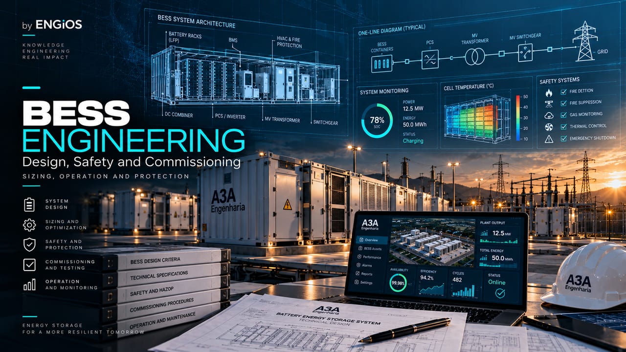
Complete engineering guide to BESS covering applications, sizing, architecture, electrical integration, safety, procurement, commissioning, warranties, operation, degradation, and lifecycle management.
Check it out!
A BESS — Battery Energy Storage System — is an electrical energy storage system using batteries, designed to receive energy, store it, and return it to the facility or grid in a controlled manner. In engineering, it should not be treated as a “battery container,” but as a multidisciplinary system combining an electrochemical subsystem, power conversion, protection, transformation, metering, automation, HVAC, safety, telecommunications, civil infrastructure, and grid integration.
Proper design starts with the function the BESS must perform and the definition of the performance boundary. Power in MW, energy in MWh, duration in hours, efficiency, availability, dynamic response, reactive capability, service life, and safety must be specified using the same measurement basis and operating conditions. Without this, vendor proposals may appear comparable while actually representing different systems.
This guide covers the complete BESS engineering lifecycle: applications, battery technologies, sizing, architecture, BESS Readiness, electrical and civil design, integration studies, protection, power quality, Grid Forming and Grid Following, BMS/PCS/EMS/SCADA, cybersecurity, thermal runaway safety, environmental requirements, the Brazilian regulatory framework, specification, procurement, QA/QC, construction, FAT, SAT, commissioning, performance testing, warranties, operation, degradation, augmentation, incidents, end of life, and procurement of engineering services.
BESS must be treated as an engineering system
Technical responsibility for a BESS project does not end with battery selection. Final performance depends on the interaction among subsystems and the infrastructure to which the system is connected. A PCS may meet rated power in isolation and the project may still fail to deliver that power at the point of connection because of transformer, cable, temperature, auxiliary supply, protection, voltage, EMS dispatch, or grid constraints.
The first decision is therefore to define the system boundary. In an industrial project, the boundary may be the plant’s medium-voltage bus; in a co-located plant, the point of connection may be at the collector substation; in a standalone BESS, the project may include a step-up substation, restricted-interest network, auxiliary services, telecommunications, and supervisory systems. The adopted boundary must be the same for sizing, efficiency, warranties, and acceptance testing.
BESS is part of a broader transformation of electrical infrastructure. The role of storage, distributed generation, electrification, and flexibility is organized in the Energy Transition and Electrical Infrastructure HUB, while this guide specifically addresses electrochemical storage engineering.
Terminology that must be standardized in the project
The same project may use similar terms for different concepts. The Technical Specification and Design Basis should define at least:
- rated BESS power and where it is measured;
- rated or nameplate energy of the battery subsystem;
- usable DC energy and usable AC energy;
- state of charge — SOC;
- state of health — SOH;
- depth of discharge — DoD;
- C-rate, where applicable to the electrochemical subsystem;
- round-trip efficiency — RTE;
- auxiliary consumption and whether it is included in contracted RTE;
- technical availability and permitted exclusions;
- active and reactive power at the point of connection;
- continuous operating limit and transient overload capability;
- design life, warranty life, and augmentation horizon.
Without this standardization, a “90% efficiency” warranty, for example, may refer to the PCS, the battery+PCS assembly, or the complete system including HVAC, transformer, and auxiliaries. These are different metrics.
BESS applications: function must come before equipment
The same technology can be sized very differently depending on the application. A peak shaving system is governed by the demand profile and the power to be limited; an energy-shifting system depends on the charge/discharge window and daily energy; a fast-response system may require higher relative power and dynamic control; a resilience system requires analysis of critical loads, autonomy, transfer, islanding, and coordination with other sources.
The main application families include:
| Application | Dominant design variable | Engineering issues |
| Peak shaving | peak kW/MW and duration | load profile, contracted demand, operating margin, cycles |
| Load shifting | MWh shifted per window | tariff, duration, efficiency, initial/final SOC |
| Renewable integration | variability and generation constraint | ramp control, curtailment, point of connection, forecasting |
| Energy arbitrage | energy and number of cycles | RTE, degradation, operating window, usable capacity |
| Grid services | dynamic response and power | active/reactive control, telemetry, interconnection requirements |
| Microgrid/islanding | stability and continuity | Grid Forming, black start, protection, synchronization, reserve |
| Critical power | autonomy and quality | transfer time, selectivity, UPS/generator, critical loads |
| Capacity support | MW available during critical periods | availability, degradation, SOC reserve, capacity testing |
Applications can be stacked (revenue stacking or service stacking), but this requires SOC governance and priorities. It is not technically correct to promise all energy simultaneously for arbitrage and all reserve for contingency. The EMS must account for minimum reserves, throughput limits, warranty restrictions, and priority rules.
For behind-the-meter applications, the article BESS Behind-the-Meter explores integration in companies and industrial facilities. For critical power, it is important to distinguish BESS, UPS, and generator sets; these resources may be complementary, but they are not equivalent in behavior, autonomy, transfer, and electrical function.
Functional requirements before technology selection
Before requesting a proposal, the owner should convert the use case into measurable requirements. A sound functional matrix includes, at minimum:
- charge and discharge power;
- required usable energy at the metering point;
- minimum delivery duration;
- daily or annual operating profile;
- estimated number of equivalent full cycles;
- minimum and maximum SOC limits;
- setpoint response and tracking accuracy;
- reactive power capability and voltage control;
- need for islanded or Grid Forming operation;
- performance at design ambient temperature;
- required availability;
- safety and emergency requirements;
- design life and expected performance over the years;
- augmentation or replacement strategy;
- telemetry, historian, and SCADA/EMS integration requirements;
- warranty and acceptance-testing criteria.
The result of this stage is a set of Owner’s Requirements sufficiently clear to enable sizing and technical competition among vendors.
Battery technologies and how to select the chemistry
“BESS” defines the system function, not a specific chemistry. Stationary systems may use different technologies, each with trade-offs in density, cycle life, power, safety, thermal range, footprint, maintenance, maturity, and commercial availability.
Lithium iron phosphate — LFP
LFP is widely used in stationary storage because it combines good cycle life, high efficiency, and favorable thermal-stability characteristics compared with some higher-energy-density chemistries. This does not mean absence of risk: LFP cells can also enter thermal runaway, release flammable gases, and require prevention, detection, ventilation, containment, and response design.
Nickel manganese cobalt — NMC
NMC offers higher energy density and is common in applications where mass and volume carry greater weight. In stationary projects, selection should consider temperature, SOC strategy, cycling profile, and product and installation safety evidence. The comparison should not be reduced to price per kWh.
Sodium-ion, flow batteries, and other technologies
Sodium-ion is gaining commercial traction and may change the decision matrix in future projects. Flow batteries have architectures and behavior different from lithium-ion batteries and may be attractive for long-duration applications, but with their own footprint, balance-of-plant, and requirements. Lead-acid remains technically applicable to certain uses, although it generally has cycle-life and density limitations compared with newer technologies.
| Criterion | Engineering question |
| Safety | what failure modes and test evidence exist for cell, module, unit, and installation? |
| Energy | what usable energy can be guaranteed under project conditions? |
| Power | what continuous and transient power is available at each SOC and temperature? |
| Cycling | what throughput and number of cycles are compatible with the warranty? |
| Temperature | what derating occurs at environmental extremes? |
| Degradation | what SOH and capacity curve was assumed? |
| Footprint | what area, spacing, access, and auxiliary infrastructure are required? |
| Maintenance | what interventions, parts, and competencies are required? |
| Replacement | what strategy exists for modules, racks, and technology over the lifecycle? |
| End of life | how will decommissioning, transport, reuse, or recycling be handled? |
Second-life batteries and repurposing
The use of repurposed batteries requires additional attention to traceability, usage history, SOH dispersion, screening criteria, safety, balancing, and warranty. IEC TR 62933-2-201:2024 specifically discusses testing and design, manufacturing, operation, and maintenance issues for BESS using reused or repurposed batteries. The decision should be based on condition data, not merely on the lower-cost origin of the asset.
Design Basis: the document that governs the BESS project
A complete BESS needs a Design Basis — or equivalent design-criteria document — consolidating assumptions, applicable standards, boundary conditions, and performance requirements. Without it, each discipline begins adopting different assumptions and the project loses consistency.
The document should record at least:
- application and operating philosophy;
- physical and functional project boundary;
- point of connection and voltage levels;
- power, energy, duration, and reference conditions;
- cycling and dispatch profile;
- environmental conditions: temperature, humidity, altitude, corrosivity, flooding, wind, and others as applicable;
- design life and degradation strategy;
- safety and emergency-response criteria;
- grounding and protection philosophy;
- control, telemetry, communication, and cybersecurity requirements;
- availability and maintenance criteria;
- FAT, SAT, performance-test, and acceptance criteria;
- applicable standards and regulations;
- responsibilities and interfaces among BESS vendor, EPC, designer, owner, utility/ONS, and authorities.
IEC 62933-3-1:2025 is especially useful as a planning and performance-assessment reference because it connects functions, sizing, operation, monitoring, testing, and maintenance. It should be applied together with electrical and safety standards and requirements specific to the Brazilian system.
Sizing power, energy, and duration
Sizing a BESS means converting a service profile into technical capacity that continues to meet the requirement throughout its life under the project’s environmental and operating conditions. Power and energy are different variables and must be treated separately.
The basic relationship between energy and power is useful for an initial estimate:
rated duration ≈ usable energy / discharge power
A 20 MW BESS with 40 MWh usable energy can, under idealized conditions, sustain rated power for approximately two hours. In actual engineering, however, SOC limits, derating, efficiency, temperature, auxiliaries, degradation, and operating reserves must be considered.
The mathematical detail is addressed in BESS: how to size power, energy, and duration. Here, the central point is the design methodology.
From gross energy to guaranteed energy
The sizing chain should distinguish:
- rated cell/module energy;
- permitted SOC window;
- usable DC energy;
- internal and conversion losses;
- auxiliary consumption;
- energy available at the contractual metering point;
- margin for degradation over the lifecycle.
Nameplate energy is not automatically the energy delivered to the customer. The contract should state whether the guarantee is beginning of life (BOL), end of life (EOL), or whether there is an annual minimum-capacity curve.
Sizing by scenario and duty cycle
The BESS should be simulated using representative time series. For peak shaving, the analysis should identify the shape, duration, and recurrence of peaks. For arbitrage, charge/discharge windows and effectively available energy must be represented. For grid support, response requirements and SOC reserve must be considered. For backup, contingencies and critical-load profiles must be modeled.
A single “typical day” is rarely sufficient. The study should cover seasonal scenarios, extreme days, load growth, outages, and temperature conditions that cause derating.
C-rate, power, and temperature
Battery power is limited by electrochemistry, electronics, temperature, and protection strategy. C-rate provides a relationship between current/power and capacity, but does not replace manufacturer curves. Maximum power may vary with SOC and temperature; performance requirements should therefore be contracted under the critical conditions relevant to the project.
Efficiency, losses, and measurement boundary
Round-trip efficiency — RTE — must be defined together with the test boundary. Measuring only the PCS produces a different result from measuring the BESS on the medium-voltage side including transformer, HVAC, BMS, pumps, fans, and other auxiliaries.
For technical comparison, the tender or specification should state:
- charge-energy metering point;
- discharge-energy metering point;
- test-cycle power and duration;
- initial and final SOC;
- system temperature and thermal condition;
- which auxiliaries are included;
- degradation condition or SOH;
- instrument accuracy and class;
- treatment of stabilization periods and standby consumption.
RTE may be excellent at one operating point and lower at partial load. Projects operating much of the time away from rated power therefore need to assess efficiency curves, not only a single number.
Auxiliary loads
HVAC is often significant, but it is not the only auxiliary load. Control systems, detection, pumps, ventilation, lighting, heating, communications, control UPS, and safety equipment also consume energy. The energy balance should separate fixed, variable, and environmentally dependent consumption.
BESS functional architecture
A arquitetura deve deixar claras as cadeias de potência, controle, proteção e segurança. Uma representação simplificada é:
The diagram does not represent a universal topology. Systems may use distributed or centralized PCS, low- or medium-voltage coupling, block transformers, shared buses, and different levels of control hierarchy.
Battery subsystem
The battery is typically organized as cell → module → rack → string → unit/container. The design must verify maximum and minimum voltages, insulation coordination, DC protection, contactors, fuses, insulation monitoring where applicable, balancing, temperature measurement, and safe isolation capability.
BMS
The BMS protects and supervises the electrochemical subsystem. Its functions include monitoring voltages, temperatures, currents, SOC, and SOH; controlling contactors; balancing; imposing charge/discharge limits; generating alarms; and transmitting dynamic limits to the PCS/EMS. Final authority under an unsafe condition must be defined: an external command cannot force the battery beyond protection limits.
PCS
The Power Conversion System converts DC/AC and controls active and reactive power. Its requirements may include ramps, setpoint response, power factor, voltage control, grid-support functions, ride-through, Grid Following, or Grid Forming, depending on the application.
Transformeres e média tensão
Transformer, cubículos, relés, cabos, medição e aterramento fazem parte do desempenho. A seleção precisa considerar fluxo bidirecional, harmônicas, regime de carga, capacidade térmica, coordenação de proteção, corrente de energização e requisitos da rede.
EMS, PPC, and SCADA
The EMS converts operating objectives into commands. The PPC — Power Plant Controller, where applicable — coordinates behavior at the point of connection. SCADA provides supervision, alarms, historian functions, and the operating interface. Responsibilities among these systems must be defined in a functional matrix, not inferred after installation.
BESS Readiness: due diligence before specifying equipment
The existing facility must be assessed before desired power and energy are converted into a purchase. Transformer, switchboard, protection, grounding, physical-space, automation, and retrofit constraints can completely change the BESS scope.
An existing facility may not have the electrical, physical, or operational capacity to receive a BESS at the desired rating. BESS Readiness should precede procurement when the system will be integrated into an existing plant.
Due diligence must answer four questions: where to connect, how much the infrastructure can support, what upgrades are required, and which risks can change CAPEX/schedule.
Document review
The team should collect and validate:
- single-line and functional diagrams;
- designs and As-Built documentation;
- transformer, main switchboard, switchgear, cable, and protection data;
- existing settings and selectivity studies;
- demand and power-quality measurements;
- failure and intervention history;
- grounding and lightning-protection designs;
- point-of-connection data and grid-use agreements, where applicable;
- civil drawings and available areas;
- fire and emergency documentation;
- existing automation, SCADA, and telecommunications systems.
Old documentation must be checked against field conditions. The physical and functional inventory must identify discrepancies affecting integration capacity.
Existing electrical capacity
Transformers, busbars, panels, cables, switching devices, and protection must be assessed. A BESS changes power flow because it can act as a load while charging and as a source while discharging. This can create conditions absent from the original design, including reverse flow through transformers and feeders.
The articles on transformer capacity and main switchboard, panel, and feeder capacity explore this assessment in greater depth.
Physical and operational readiness
The area must accommodate equipment, technical clearances, circulation, maintenance, eventual module/container replacement, emergency access, drainage, foundations, cable trays/conduits, electrical rooms, telecommunications, and physical security. A clear isolation and emergency-response strategy must also exist.
AC-coupled, DC-coupled architectures and point-of-connection topology
In AC-coupled systems, the battery and generation source generally have independent converters and meet on an AC bus. This architecture tends to facilitate retrofit and independent operation. In DC-coupled arrangements, generation and battery may share part of the conversion chain, which can reduce conversions in certain power-flow paths and recover energy otherwise limited by clipping, but increases control dependencies and DC-side compatibility requirements.
The choice should not be made based on efficiency slogans. It is necessary to assess:
- project objective;
- existing infrastructure;
- generation and load profile;
- converter ratings;
- grid-charging capability, where permitted;
- losses along each energy path;
- availability and failure modes;
- expansion flexibility;
- maintenance strategy;
- metering and regulatory requirements;
- behavior at the point of connection.
It is also necessary to choose among centralized PCS, distributed PCS, or intermediate architectures. More units may increase granularity and fault tolerance, but also increase equipment count, communications, and maintenance points.
Electrical design and integration studies
Bidirectional power flow, inverters, and new operating conditions require review of capacity, short circuit, protection, selectivity, and power quality. The design must technically demonstrate that the facility and point of connection can support all intended charge and discharge states.
A BESS is an inverter-based controlled source and also a controlled load. Electrical design must analyze both directions of power flow and all relevant states: off, charging, discharging, standby, contingency, islanding where applicable, energization, and restoration.
ABNT NBR 5410 provides requirements for low-voltage installations and includes provisions for storage batteries; ABNT NBR 14039:2021 structures requirements for medium-voltage installations from 1 kV to 36.2 kV, including protection, wiring systems, grounding, verification, maintenance, and substations. For modern BESS, these standards must be combined with storage-specific, manufacturer, interconnection, and safety requirements.
Load flow
The study verifies voltages, currents, transformer and feeder loading, and behavior under different states. It should include maximum load, minimum load, BESS at maximum charging, maximum discharge, and scenarios with distributed generation where present.
Short circuit
Power-electronic converters contribute fault current differently from synchronous machines and may limit current through control. The short-circuit model must represent PCS contribution consistently with the software and manufacturer data. The analysis must confirm interrupting ratings and thermal/mechanical withstand of equipment.
Protection selectivity and coordination
Protection must distinguish internal and external faults, operate with power flow in both directions, and coordinate BESS protection with the facility and grid. Functions may include overcurrent, voltage, frequency, directional power, differential, breaker failure, synchronism, and others depending on the architecture.
The article Protection in bidirectional systems explains why the protection philosophy must be reviewed when reverse power flow is introduced.
Anti-islanding and synchronization
When the BESS must not sustain an unintended island, disconnection logic must meet applicable requirements. When islanded operation is intentional, the architecture changes: there must be a source capable of forming the voltage/frequency reference, a separation/reconnection sequence, and coordination of loads and generation. Reconnection requires synchronism verification and closing authorization.
Power quality and harmonics
The PCS is a power-electronic load/source. Harmonic studies should consider the manufacturer spectrum, grid impedance, capacitor banks, filters, resonances, and operating conditions. IEEE 519:2022 is an international reference for distortion objectives at the point of common coupling. In Brazil, utility requirements and PRODIST or other applicable procedures must also be checked according to the interconnection.
The topic is developed further in the content on electrical harmonics and power quality with inverters, BESS, and distributed generation.
Grounding, bonding, lightning protection, and surges
The design must coordinate power, protective, and control grounding with metallic structures. The analysis includes touch and step voltages where relevant, protective continuity, bonding, surge protection, and lightning exposure. The ABNT NBR 5419:2026 series should be assessed according to the configuration and site risk analysis.
RMS and EMT studies
RMS models support many steady-state and electromechanical-dynamic analyses. EMT studies become relevant when fast control phenomena and interactions among inverters are not adequately represented by RMS models, especially in weak grids, high concentrations of IBRs, and specific stability/control analyses. There should be no automatic rule that “every BESS requires EMT”; the need depends on the system and interconnection requirements.
The article Electrical studies for BESS organizes the study set and its dependencies.
Grid Following, Grid Forming, and stability
A Grid Following (GFL) PCS operates by following an existing voltage/frequency reference. Grid Forming (GFM) implements controls capable of establishing or sustaining an electrical reference according to a defined strategy. The choice should not be treated as a commercial checkbox; it is a capability that must be specified and tested.
Applications involving microgrids, black start, weak systems, or high penetration of inverters may require more sophisticated behavior. In transmission and subtransmission, IEEE 2800-2022 provides an important reference for IBR capabilities and performance, including ride-through, active/reactive control, dynamic support, power quality, and protection.
Grid Following vs. Grid Forming compares the control architectures. The article on power-system stability with inverters further discusses weak grids, control interactions, and the need for adequate models.
The requirement must be functional
Instead of writing only “Grid Forming PCS,” the specification should define expected behavior: island operation, black start, voltage/frequency formation, droop control, disturbance response, load sharing, synchronization, reactive capability, ride-through, and stability criteria. The vendor must provide the models and parameters required for validation.
BMS, PCS, EMS, PPC, and SCADA: control hierarchy
A reliable BESS needs a clear authority architecture. The BMS protects the battery; the PCS controls conversion and electrical response; the EMS determines dispatch and optimization; the PPC controls requirements at the point of connection; and SCADA supervises and records. Some products combine functions, while others distribute them.
The control matrix should indicate, for each function:
| Function | Responsible system | Main input | Output/action | Fallback |
| charge/discharge limit | BMS | voltage, temperature, SOC | permitted limit | reduce/block power |
| P/Q control | PCS/PPC | setpoint and measurements | inverter current | safe mode |
| SOC management | EMS | forecast, state, strategy | charge/discharge schedule | minimum reserve |
| PCC regulation | PPC | point-of-connection meter | setpoints to PCS | local limit |
| alarms/events | SCADA | all subsystems | recording and display | local alarm |
| emergency | Safety/BMS/PLC | critical-condition detection | trip/isolation | safe state |
The article BESS, SCADA, and EMS details the supervision and control architecture.
Alarm philosophy
Alarms must be classified by severity, cause, required action, delay, hysteresis, and reset mechanism. A list of thousands of tags without an operating rationale is not an alarm philosophy. Safety events should be treated differently from maintenance warnings and operating deviations.
Time synchronization and historian
Failure analysis requires correlated events. BMS, PCS, relays, PPC, and SCADA should have a consistent time-synchronization strategy and sufficient resolution for the phenomena under investigation. Logs must be retained and exportable.
Communications and OT cybersecurity
A connected BESS may include vendor remote access, cloud integrations, industrial protocols, local servers, gateways, and connection to the owner’s SCADA. This surface must be treated as a critical OT environment.
Typical controls include:
- network segmentation and zones/conduits;
- firewalls and allowlists;
- controlled, temporary, auditable remote access;
- strong authentication and account management;
- least privilege;
- asset and version inventory;
- firmware update and validation policy;
- configuration backups;
- vulnerability management compatible with operational availability;
- logging and audit trail;
- disabling unused services and ports;
- cyber-incident response.
The IEC 62443 family is an important reference for industrial automation and control-system security. For storage modeling and integration in IEC 61850 environments, IEC TR 61850-90-9:2020 describes an information model for grid-integrated energy-storage systems.
Cybersecurity must enter procurement: default credentials, cloud dependency, licenses, proprietary VPNs, required ports, support lifecycle, SBOM where available, and patch responsibilities must be known before contracting.
BESS safety: thermal runaway and defense in depth
Safety cannot be an isolated section added at the end of the project. It must influence cell selection, module arrangement, ventilation, spacing, detection, control, emergency response, layout, maintenance, and deployment criteria.
Thermal runaway is an uncontrolled self-heating process within a cell. It may be initiated by internal defects or thermal, electrical, or mechanical abuse and can progress to gas release, propagation among cells/modules, fire, re-ignition, and deflagration risk. Engineering must prevent initiation where possible, detect abnormalities early, limit propagation, and create conditions for safe response.
Protection layers
A defense-in-depth strategy may include:
- cell quality and protection;
- BMS monitoring;
- temperature control and HVAC;
- electrical protection and fault isolation;
- smoke, heat, and/or gas detection as appropriate;
- ventilation and gas management where applicable;
- compartmentation and propagation limitation;
- active fire protection where applicable;
- access control and safety distances;
- response plan, isolation, and emergency interface.
There is no universal extinguishing agent that resolves every BESS scenario. The strategy must be consistent with chemistry, product, test evidence, installation configuration, local authority requirements, and emergency philosophy.
UL 9540, UL 9540A, and NFPA 855 are not the same thing
UL 9540 is a safety standard for energy-storage systems/equipment. UL 9540A is a test method for evaluating thermal-runaway propagation and fire behavior. UL describes testing at cell, module, unit, and installation levels depending on edition and application. NFPA 855 is a North American reference for installation of stationary energy-storage systems.
These documents have substantial technical value and may be required by insurers, vendors, lenders, or design criteria, but their application in Brazil must be defined within the project’s regulatory and contractual context; they should not automatically be presented as Brazilian law.
IEC 62933-5-2:2025 addresses safety requirements for grid-integrated electrochemical systems throughout the lifecycle and is a central international reference for structuring a BESS safety case.
The article BESS safety: thermal runaway, UL 9540A, and fire protection explores the subject in greater depth.
Safety case, risk analysis, and emergency response
Higher-criticality projects should consolidate risks and controls in a safety case or equivalent evidence framework. ABNT NBR ISO 31000:2018 provides a general approach for risk identification, analysis, evaluation, treatment, monitoring, and recording.
The risk register should cover, as applicable:
- overtemperature and thermal failures;
- overvoltage, overcurrent, and short circuit;
- arc flash and electric shock;
- DC insulation failure;
- flooding and water ingress;
- lightning and surges;
- external fire;
- gas release and deflagration;
- HVAC failure;
- firmware or control error;
- loss of communication;
- operation outside warranty conditions;
- collision/mechanical impact;
- maintenance and lifting risks;
- unauthorized access;
- site-specific environmental events.
IEC 62933-4-3:2025 addresses the effects of environmental conditions on BESS, including lightning, seismic activity, water, air, flora, fauna, and human factors. This reinforces that safety design is not limited to battery chemistry.
Emergency plan
The plan must define detection, event classification, automatic actions, manual commands, electrical isolation, access restrictions, communications, contact with the emergency brigade/fire department, post-event monitoring, and re-entry criteria. It must also define who has authority to re-energize a system that has undergone a critical condition.
Civil design, site development, and layout
Civil engineering directly affects safety, availability, and maintenance. BESS location should consider topography, geotechnical conditions, drainage, flooding, access, foundations, equipment weight, cable routes, emergency routes, lifting, and future replacement.
Drainage and flooding
Critical electrical equipment should not be located without assessing elevations, surface drainage, and flood history. The analysis must consider design rainfall, runoff paths, obstructions, and the consequences of water reaching containers, panels, and transformers.
Maintenance access
The layout should provide for removal of modules/racks or complete units according to the vendor strategy. Simply fitting containers on the site does not guarantee maintainability. Opening envelopes, corridors, maneuvering areas, cranes, and block isolation during maintenance must be assessed.
Separation distances and propagation
Spacing between units should not be defined by a generic rule taken from another product. It must be supported by applicable standards, local requirements, system test data, and the firefighting/control strategy. Relevant-scale UL 9540A results can inform this decision when that framework is adopted.
Noise
PCS, transformers, and HVAC can generate continuous and tonal noise. Projects near sensitive areas require acoustic analysis, particularly because cooling systems operate even when electrical power is low.
HVAC, thermal management, and environmental conditions
Temperature affects power, degradation, availability, and safety. The thermal system must be sized considering internal losses, outdoor temperature, solar radiation, container occupancy, required redundancy, and failure modes.
A sound design defines:
- normal operating temperature range;
- derating range;
- shutdown condition;
- thermal uniformity among modules/racks;
- HVAC capacity under extreme conditions;
- redundancy philosophy;
- monitoring of filters, fans, pumps, and refrigerant;
- operation after partial loss of the thermal system;
- interaction between normal ventilation and emergency strategy.
The specification should clarify whether guaranteed power, energy, and service life assume a specific controlled temperature. Otherwise, the owner may contract performance that exists only under laboratory conditions.
Lightning protection, surges, and electromagnetic interference
BESS combines power electronics, communication networks, sensors, and extensive metallic structures. Lightning and surge protection must be coordinated with grounding and the project’s electromagnetic zones.
The ABNT NBR 5419:2026 series should be evaluated from risk analysis through external protection, bonding, SPDs, and protection of internal electrical/electronic systems. Power and communication cables, outdoor routes, and substation interfaces must also be included in the analysis.
Electromagnetic compatibility is particularly relevant to BMS, relays, industrial networks, and low-level signals. Physical segregation, shielding, functional grounding, and interface selection must be consistent with the electromagnetic environment.
Brazilian regulatory framework for storage in 2026
Energy storage acquired a specific regulatory framework in the Brazilian power sector. In 2026, ANEEL regulated standalone Energy Storage Systems — SAE — through Normative Resolution No. 1,161/2026 and established rules for co-location with generating plants through REN No. 1,162/2026.
For standalone SAE, ANEEL describes DRO-SAE and authorization procedures, technical documentation, general arrangement, storage capacity, power, and interconnection according to the applicable modality. For co-location, documentation includes the general arrangement, technical study with operating profile, overall efficiency, discharge power, storage capacity, technology, compatible environmental license, and grid-access instruments where applicable.
This does not mean every behind-the-meter BESS follows the same authorization route. Configuration, purpose, point of connection, market, and relationship with the grid determine which regulatory requirements apply. The project should produce a regulatory applicability matrix before freezing the architecture.
Access and interconnection
In addition to authorization where applicable, the project may depend on an access opinion or equivalent document, CUSD/CUST, utility or ONS requirements, metering, and telemetry. These requirements influence electrical design and control and should not be deferred to the final phase.
NR-10 and occupational safety
In September 2026, the current wording of NR-10 remains the previous version until May 31, 2027. The new wording published by MTE Ordinance No. 737/2026 takes effect on June 1, 2027, except for specific deadlines. Projects spanning this transition must track the requirements and plan documentation, risk analysis, and operating procedures consistently with the schedule.
Engineering deliverables by phase
A mature BESS is built through verifiable deliverables. The set varies by contracting model and project size, but the following matrix helps structure the scope.
| Phase | Typical deliverables |
| Feasibility / Due Diligence | survey, load/generation profile, alternatives, BESS Readiness, risks, power/energy estimate, indicative CAPEX |
| Conceptual | Design Basis, operating philosophy, architecture, point of connection, preliminary layout, safety assumptions |
| Basic Design | single-line diagram, load balance, main sizing, electrical studies, control requirements, specifications, safety criteria |
| Procurement | technical requisition, datasheet, TBE, deviation matrix, vendor data requirement, ITP/FAT, warranties |
| Detailed Design | IFC drawings, cables, grounding, protection, control, telecom, civil, interfaces, installation details |
| Construction | RFIs, submittals, inspections, QA/QC, NCRs, redlines, punch list |
| Commissioning | plan, procedures, FAT/SAT, functional/integrated tests, performance test, reports |
| Handover | As-Built, settings, backups, manuals, Data Book, training, spare parts, closed punch list |
| Operation | maintenance plan, KPIs, performance baseline, firmware policy, warranty, augmentation, and end of life |
The purpose of design is not to produce documents for bureaucracy. Each deliverable should reduce uncertainty, define an interface, or provide evidence of compliance.
Technical specification: contract performance, not only nameplate capacity
A BESS specification must be oriented toward verifiable performance. “10 MW / 20 MWh BESS” is insufficient because it does not define where power is measured, how much energy is usable, at what temperature, with what degradation, which auxiliaries are included, or how the result will be demonstrated.
Minimum performance requirements
The specification should address, as applicable:
- continuous active charge and discharge power;
- usable energy at the metering point;
- duration;
- RTE and boundary;
- reactive capability and P-Q curve;
- setpoint response;
- ramp rate;
- voltage/frequency range;
- ride-through;
- availability;
- auxiliary consumption;
- noise;
- operating temperature and derating;
- degradation and guaranteed capacity by year;
- throughput or cycles covered by warranty;
- Grid Forming requirements, where applicable;
- communication and telemetry requirements;
- safety functions;
- maintenance and spare parts.
Documentation requirements
Vendor data should include, at minimum, diagrams, datasheets, performance curves, alarm/tag lists, control philosophy, manuals, applicable certificates and test reports, electrical models, protection parameters, interface drawings, foundation and cable requirements, auxiliary-load list, and maintenance plan.
BESS procurement and technical bid equalization
BESS procurement must equalize supply boundary, usable energy, RTE, degradation, warranties, safety, models, control, FAT/SAT, and O&M. Comparing only BRL/MWh transfers scope and risk differences to implementation.
Procurement must compare proposals on the same technical basis. A TBE — Technical Bid Evaluation — must convert commercial differences into measurable differences in scope and performance.
The article BESS Procurement explores the process in greater depth.
Equalization matrix
The comparison should normalize:
| Topic | What to compare |
| Supply boundary | battery, PCS, transformer, MV, HVAC, fire, EMS, SCADA, cables, civil |
| Power | metering location, temperature, SOC, duration, overload |
| Energy | gross/net, AC/DC, BOL/EOL, SOC window |
| Efficiency | boundary, cycle, auxiliaries, temperature |
| Degradation | annual curve, assumptions, augmentation |
| Warranty | years, throughput, cycles, exclusions, availability |
| Safety | standards, tests, tested configuration, deviations |
| Control | EMS/PPC, protocols, response, GFL/GFM |
| Studies/models | formats, validation, deadlines, confidentiality |
| Services | engineering, supervision, FAT, SAT, start-up, training |
| O&M | maintenance, SLA, parts, remote support, obsolescence |
A cheaper proposal may transfer the transformer, switchgear, protection, SCADA integration, studies, and civil engineering to the owner. Without equalization, the economic comparison loses validity.
Deviations and exceptions
Every deviation must have a status: accepted, conditionally accepted, rejected, or pending. The vendor should not be able to convert a mandatory requirement into “partial compliance” without contractual effect. The deviation matrix should form part of the contract or be formally incorporated into the reference documents.
Warranties: energy, efficiency, availability, and degradation
Warranties must be measurable. A robust contract defines the measurement method, test condition, tolerances, exclusions, remediation, and consequences of noncompliance.
Capacity warranty
Capacity may be expressed as minimum usable energy by year or as an SOH curve. The following must be clear:
- metering point;
- reference temperature;
- initial/final SOC;
- charge/discharge rate;
- rest/stabilization, if required;
- permitted corrections;
- meter calibration condition;
- effect of unavailable modules.
RTE warranty
RTE must use the same boundary and contracted operating regime. Different tests are not comparable.
Availability
The availability formula must define the period, excluded events, partial unavailability, derating, scheduled maintenance, and outages caused by equipment outside the vendor boundary. Loss of 20% of power because of one block failure should not necessarily be counted as total unavailability.
Throughput and cycles
Manufacturers may limit warranty by processed energy, equivalent full cycles, temperature, SOC, and power. The EMS must control operation so the warranty is not inadvertently consumed.
Degradation, SOH, and augmentation
Batteries lose capacity and may change internal resistance over time. Calendar degradation is related to time and storage/operating conditions, while cycling degradation is related to processed energy, DoD, C-rate, temperature, and other factors.
Sizing can follow different strategies:
- initial oversizing: install additional capacity to meet the requirement at the end of the horizon;
- augmentation: add modules/racks/units throughout the lifecycle;
- partial repowering: replace components at defined milestones;
- combination: moderate oversizing + planned augmentation.
The strategy must consider future compatibility. Mixing cell generations may require specific BMS and operating rules. The contract should clarify who supplies augmentation, when, under what criteria, and how performance will be revalidated.
SOH is not a single absolute truth
SOH estimation methods vary. The indicator shown by the BMS should be correlated with capacity tests and the contractual methodology. For warranties, the metric must be reproducible and auditable.
Operating-control and dispatch design
The EMS must implement the owner’s strategy, not merely command charge and discharge. Requirements may include forecasting, optimization, tariff constraints, SOC reserve, warranty limits, demand control, dispatch based on price/external signals, and coordination with renewable generation.
Service priority
When multiple services are stacked, a priority matrix prevents conflicts. For example, an emergency reserve may constrain minimum SOC; peak shaving uses energy above that reserve; and fast services may use power margin without consuming all reserved energy.
Fallback and degraded modes
The design should define behavior upon loss of:
- communication with the remote center;
- EMS;
- PPC;
- PCC meter;
- time synchronization;
- one PCS block;
- part of the BMS;
- connection to a cloud service.
A safe system should degrade predictably and should not depend on external connectivity for essential protection functions.
Manufacturing QA/QC and vendor-data management
BESS quality begins before FAT. The inspection and test plan — ITP/PIT — should identify hold points, witness points, manufacturing documents, and release criteria.
QA/QC items may include:
- cell and module traceability;
- rack and busbar assembly inspection;
- torque and connections;
- cable and harness inspection;
- insulation tests;
- sensor calibration;
- BMS testing;
- PCS and panel inspection;
- HVAC verification;
- fire detection/protection system;
- software and firmware versions;
- configuration documentation;
- integrated functional tests.
Vendor-data management must control revisions, comments, approvals, and pending items. Drawings “approved with comments” should not proceed to manufacturing until critical conditions have been addressed.
FAT: test before bringing problems to site
FAT should verify what can be demonstrated at the factory with greater efficiency and lower risk. Content depends on the supply boundary and availability of integrated hardware.
A robust program may include:
- visual and document inspection;
- identification and traceability;
- I/O verification;
- alarms and trips;
- BMS–PCS–EMS/SCADA communication;
- simulation of sensor and subsystem failures;
- responses to SOC/temperature limits;
- energization/de-energization sequence;
- E-stop and interlocks;
- active/reactive power control;
- network/protocol tests;
- configuration backup and restoration;
- software-version validation;
- specific safety items.
FAT does not replace SAT. Some performance depends on the installation, transformer, grid, cables, metering, and local integration and can only be accepted on site.
Construction, installation, and field QA/QC
The BESS should arrive at a prepared site. Storing containers on unfinished ground, exposing them to conditions outside requirements, or partially energizing without construction controls can create risks and loss of warranty.
Receipt and storage
Receiving inspection should check transport damage, shock indicators where used, physical condition, seals, documentation, preservation, and storage limits. The vendor should specify SOC and recharge requirements for extended storage periods.
Electrical installation
QA/QC should record:
- connection torque;
- cable tests;
- continuity and grounding;
- medium-voltage termination;
- identification;
- relay settings;
- transformer tests;
- fiber and communications;
- auxiliary supply;
- interlocks.
Redlines and As-Built
Field changes must feed controlled redlines and then As-Built documentation. Commissioning against outdated diagrams increases operational risk and compromises traceability.
Pre-commissioning and readiness for energization
Pre-commissioning demonstrates that equipment and installations are correctly assembled and ready to receive power. A formal Ready for Energization gate should exist.
The gate may require:
- mechanical construction complete for the area;
- approved installation inspections and tests;
- grounding released;
- protection configured and tested;
- interlocks proven;
- auxiliary circuits available;
- minimum operational communications;
- safety system available;
- approved documents and procedures;
- authorized team and switching plan;
- critical punch-list items closed;
- grid/utility clearance where applicable.
Energization should not be used to “find out whether the installation was built correctly.”
SAT, functional commissioning, and integrated testing
SAT verifies the system in the actual environment. Functional commissioning goes further: it proves sequences, interactions, failure modes, and integrated performance.
The article BESS Commissioning explores FAT, SAT, and acceptance in greater depth.
Functional tests
They should cover:
- charge and discharge at multiple power levels;
- P/Q control;
- SOC limits;
- alarm response;
- trips and E-stop;
- loss of communication;
- loss of auxiliaries;
- simulated HVAC failure under safe conditions;
- startup/shutdown sequence;
- local/remote control;
- service prioritization;
- interlocks;
- protection and signals to the PCC.
Integrated tests
Subsystem behavior should be verified together. An E-stop must trigger the intended actions in the battery, PCS, breakers, HVAC/safety, and SCADA. A communication failure must lead to the specified fallback. An external command must not violate BMS limits.
Performance tests and technical acceptance
Acceptance should be based on quantifiable requirements defined before purchase. Typical metrics include power, energy, RTE, response, reactive capability, initial availability, and control functions.
Power test
Demonstrates that the system delivers and/or absorbs contracted power at the defined point, for the specified duration and condition. Voltage, current, active/reactive power, SOC, temperature, and active limits should be recorded.
Energy/capacity test
Demonstrates usable energy between defined SOC and power limits. The procedure must control preconditioning, temperature, instruments, and measurement boundary.
RTE test
Runs a charge/discharge cycle according to the protocol and measures energy at the same points. If auxiliaries are included in the warranty, they must be included in the measurement.
Dynamic response
Where relevant, verifies delay, rise time, overshoot, settling, and setpoint-tracking accuracy. For grid services, dynamics may be more important than simple steady-state power.
Rejection and retest criteria
The procedure must state what happens if a test fails: investigation, correction, partial or complete repetition, costs, retest window, and impact on acceptance. Without this rule, testing becomes a demonstration with no contractual consequence.
Handover, Data Book, and final documentation
Handover transfers a verifiable installation to operations. The package should include:
- electrical, civil, control, and telecom As-Built documentation;
- equipment list and serial numbers;
- relay, PCS, BMS, EMS, and PPC settings;
- software and configuration backups;
- FAT/SAT/commissioning reports;
- certificates and test reports;
- safety documentation;
- operation and maintenance manuals;
- alarm list and cause/effect;
- maintenance plans;
- spare parts;
- warranties;
- training and records;
- support contacts and SLA;
- performance baseline;
- formally accepted residual punch-list items.
The Data Book must have an index and traceability. A folder of disconnected PDFs is not adequate handover documentation.
Operation and maintenance
The BESS must be operated within the envelope that sustains safety and warranty. The O&M plan integrates electrical, mechanical, thermal, control, and software maintenance.
Operational KPIs
Useful indicators include:
- total and block-level availability;
- charged/discharged energy;
- actual RTE;
- equivalent full cycles;
- SOH and measured capacity;
- voltage/temperature dispersion;
- auxiliary consumption;
- derating events;
- critical alarms;
- unavailability by cause;
- scheduled/unscheduled maintenance;
- communication failures;
- performance against baseline.
Trends are more useful than snapshots. A gradual increase in thermal dispersion or resistance may indicate a problem before failure occurs.
Condition-based maintenance
In addition to periodic inspections, BESS provides large volumes of data. Maintenance strategies can use trends in temperature, imbalance, fan failures, insulation, device operating counts, and PCS indicators to prioritize intervention.
Firmware, obsolescence, and configuration management
A BESS may operate for many years while control systems and cybersecurity evolve rapidly. A version inventory and approved baseline must be maintained.
Updates should undergo:
- impact assessment;
- configuration backup;
- validation in a controlled environment where possible;
- rollback plan;
- maintenance window;
- post-update functional testing;
- documentation update.
Replacement of PCS, BMS, switches, or servers over the lifecycle must also preserve protocol compatibility and security requirements.
Failure, incident, and root-cause management
Failures must generate sufficient evidence for investigation. The team should preserve logs, oscillography, SOC/temperature history, alarms, firmware versions, and protection events.
A root-cause analysis must distinguish immediate cause, contributing causes, and barrier failures. Replacing a defective module resolves the component, but not necessarily the mechanism that caused the failure.
After relevant incidents, return to service should depend on defined technical criteria. Adjacent units may need inspection, insulation validation, log review, and confirmation that detection and protection systems remain functional.
End of life, repowering, reuse, and decommissioning
End of life should be considered during design. Containers, modules, power electronics, and transformers may have different lifecycles.
A decommissioning plan should address:
- safe condition and SOC for intervention/transport according to applicable requirements;
- isolation and absence of hazardous energy;
- disassembly and lifting;
- module traceability;
- disposal, recycling, or reuse;
- removal of data and credentials from control systems;
- site restoration;
- final documentation.
Repowering may retain part of the electrical/civil infrastructure while replacing batteries or PCS. Feasibility depends on electrical, mechanical, control, and safety compatibility and the rules of the existing interconnection.
Owner’s Engineering and interface management
In projects with multiple vendors, the greatest exposure is often at interfaces: battery–PCS, PCS–transformer, EMS–SCADA, BESS–PCC, fire–BESS, and civil–equipment. An independent owner-side layer helps keep requirements, decisions, and acceptance traceable.
BESS involves the battery vendor, integrator, PCS, EPC, designers, utility/ONS, protection manufacturers, SCADA, fire safety, civil engineering, and operations. Most serious problems appear at interfaces, not necessarily within an isolated piece of equipment.
Owner’s Engineering acts as the owner-side technical-governance layer: consolidating requirements, reviewing documents, controlling interfaces, monitoring vendor data, supporting procurement, overseeing implementation, witnessing tests, and structuring acceptance.
Interface matrix
A matrix should indicate at least:
| Interface | Responsible A | Responsible B | Closure evidence |
| Battery–PCS | battery integrator | PCS vendor | electrical data + integrated test |
| PCS–transformer | PCS vendor | EPC/electrical | studies, datasheet, protection |
| BESS–PCC | EPC/designer | grid/owner | access opinion + studies + test |
| EMS–SCADA | integrator | owner automation | point list + FAT/SAT |
| Fire–BESS | vendor | safety/fire designer | cause/effect + tests |
| Civil–equipment | civil designer | manufacturer | loads/foundation/approved layout |
| Operations–vendor | owner | OEM/O&M | manuals, SLA, training |
An interface without an owner tends to become an RFI, change order, rework, or acceptance risk.
How to contract engineering for a BESS project
Contracting should clearly separate equipment supply, engineering, implementation, management/inspection, and commissioning, even when several of these scopes are concentrated in one EPC. The owner needs to know which deliverables demonstrate each obligation.
Contract object
The object should express an outcome, not merely items. Conceptual example: development, supply, integration, and commissioning of a BESS with specified usable power/energy at the PCC, including studies, protection, control, safety, documentation, and performance tests according to project requirements.
Scope and exclusions
The scope matrix should state who provides:
- batteries and BMS;
- PCS;
- transformers and medium voltage;
- cables and infrastructure;
- auxiliary services;
- HVAC;
- safety/fire;
- EMS/PPC/SCADA;
- telecommunications;
- electrical studies;
- simulation models;
- civil engineering;
- licensing and regulatory support;
- FAT/SAT;
- installation and supervision;
- training;
- O&M and spare parts.
Deliverables and milestones
Financial measurement should be linked to verifiable deliverables. Payments excessively concentrated on physical supply can reduce the owner’s leverage to obtain documentation, corrections, and performance testing.
Typical milestones may be associated with:
- approved Design Basis;
- approved Basic/Detailed Design;
- manufacturing release;
- approved FAT;
- site delivery;
- installation complete;
- energization authorized;
- approved SAT;
- approved performance test;
- accepted handover/Data Book.
Percentages should be commercially defined according to risk and contracting model; this guide does not establish a universal distribution.
Team competencies
BESS projects require integration of electrical engineering, automation/control, safety, civil, telecommunications/cybersecurity, and commissioning. Qualifications should be compatible with the contracted role; manufacturer certification does not replace system-design responsibility.
Acceptance criterion
The contract must state exactly when the system will be considered accepted. “Equipment operating” is not a criterion. Acceptance should consider documentation, punch-list items, tests, warranties, training, As-Built, and performance.
BESS project maturity gates
Gates prevent the project from advancing while carrying critical uncertainties into the next phase.
G0 — use case defined
Output: need, operating profile, technical value, and initial boundary.
G1 — Readiness and feasibility
Output: point of connection, infrastructure capacity, risks, site area, regulatory assumptions, and sizing range.
G2 — mature Basic Design
Output: Design Basis, architecture, main studies, layout, safety, and technical specification.
G3 — technically equalized procurement
Output: selected vendor with compliance matrix, resolved deviations, warranties, and contracted interfaces.
G4 — construction ready for commissioning
Output: completed installation, QA/QC, updated documentation, and critical punch-list items closed.
G5 — ready for energization
Output: protection, safety, auxiliaries, procedures, and operating authorization available.
G6 — performance demonstrated
Output: approved SAT, integrated tests, and performance tests.
G7 — handover
Output: trained operations team, Data Book, As-Built, baseline, warranties, and structured maintenance.
Red flags in BESS proposals and designs
Some signs justify technical review before proceeding:
- proposal defines only MW/MWh without a measurement boundary;
- energy is stated only as cell nameplate capacity;
- efficiency excludes auxiliaries without making this explicit;
- degradation curve does not state temperature/cycling assumptions;
- warranty depends on conditions incompatible with the expected duty cycle;
- vendor does not provide models required for studies;
- control architecture does not define BMS/EMS/PPC authority;
- safety case relies only on generic certificates without correspondence to the offered configuration;
- UL 9540A is cited without clarifying the tested level and configuration;
- design does not define a gas/deflagration strategy;
- layout ignores maintenance and unit replacement;
- there is no interface matrix;
- FAT is only a visual inspection;
- SAT has no approved procedures;
- performance test does not define boundary and instruments;
- As-Built/Data Book are not linked to acceptance;
- remote access and cybersecurity are not specified;
- augmentation is mentioned but not contracted;
- interconnection/regulation is addressed only after purchase.
Executive checklist before the investment decision
Before approving the investment, the organization should be able to answer “yes” to most of the critical questions below:
Application and performance
- Is the use case formally defined?
- Are representative load/generation time series available?
- Are power, energy, duration, and reserve SOC defined?
- Is the RTE and capacity boundary unambiguous?
- Is there a degradation curve and augmentation strategy?
Infrastructure
- Has the point of connection been validated?
- Do transformers, panels, and cables have sufficient capacity?
- Have the main electrical studies been performed or scoped?
- Does the site/layout support maintenance and emergency response?
- Has auxiliary power been sized?
Safety
- Is there a risk analysis?
- Does test evidence correspond to the proposed configuration?
- Is there a philosophy for detection, ventilation/gas control, and protection?
- Have the emergency plan and interface with authorities been considered?
Control and data
- Are BMS/PCS/EMS/PPC/SCADA responsibilities defined?
- Are protocols and the point list defined?
- Do logs and time synchronization support event investigation?
- Are remote access and cybersecurity covered by contractual requirements?
Contracting and acceptance
- Are scope and exclusions equalized?
- Do warranties have reproducible test methods?
- Do FAT/SAT/performance tests have approval criteria?
- Are handover and documentation contractual milestones?
- Is there owner-side technical governance to control interfaces?
Final considerations
A BESS is simultaneously an electrical asset, automation system, battery installation, critical infrastructure, and integration project. Result quality depends less on choosing “the best battery” and more on converting the use case into verifiable requirements, selecting an architecture compatible with the grid and environment, controlling risks, closing interfaces, and demonstrating performance through testing.
The most robust sequence is: characterize the application → perform BESS Readiness → define the Design Basis → size the system → develop studies and design → specify performance and safety → equalize vendors → control manufacturing and interfaces → install with QA/QC → commission → test capacity/efficiency/functions → deliver documentation → operate based on data → plan degradation, augmentation, and end of life.
Projects that skip these stages often transfer uncertainty to construction, warranty, or operations. Projects that treat BESS as an engineering system can convert power, energy, safety, and availability into traceable—and therefore contractible and acceptable—requirements.
Supply is technically complete only when installation, protection, control, safety, power, energy, efficiency, and documentation have been verified through test procedures with approval criteria defined before execution.
Commissioning and Technical Acceptance of Electrical Installations
Technical references
[1] ASSOCIAÇÃO BRASILEIRA DE NORMAS TÉCNICAS. ABNT NBR 5410:2004 — Instalações elétricas de baixa tensão. Rio de Janeiro: ABNT, 2004.
[2] ASSOCIAÇÃO BRASILEIRA DE NORMAS TÉCNICAS. ABNT NBR 14039:2021 — Instalações elétricas de média tensão de 1,0 kV a 36,2 kV. Rio de Janeiro: ABNT, 2021.
[3] ASSOCIAÇÃO BRASILEIRA DE NORMAS TÉCNICAS. ABNT NBR ISO 31000:2018 — Gestão de riscos — Diretrizes. Rio de Janeiro: ABNT, 2018.
[4] ASSOCIAÇÃO BRASILEIRA DE NORMAS TÉCNICAS. ABNT NBR 5419, Partes 1 a 4 — Proteção contra descargas atmosféricas. Edição 2026.
[5] INTERNATIONAL ELECTROTECHNICAL COMMISSION. IEC 62933-2-1:2017 — Electrical energy storage (EES) systems — Part 2-1: Unit parameters and testing methods — General specification. Available at: https://webstore.iec.ch/en/publication/27124.
[6] INTERNATIONAL ELECTROTECHNICAL COMMISSION. IEC TR 62933-2-201:2024 — Review of testing for BESS using repurpose and reuse batteries. Available at: https://webstore.iec.ch/en/publication/88974.
[7] INTERNATIONAL ELECTROTECHNICAL COMMISSION. IEC 62933-3-1:2025 — Planning and performance assessment of electrical energy storage systems — General specification. Available at: https://webstore.iec.ch/en/publication/75427.
[8] INTERNATIONAL ELECTROTECHNICAL COMMISSION. IEC 62933-4-3:2025 — Protection requirements of battery-based energy storage systems according to environmental conditions. Available at: https://webstore.iec.ch/en/publication/66373.
[9] INTERNATIONAL ELECTROTECHNICAL COMMISSION. IEC 62933-5-2:2025 — Safety requirements for grid-integrated EES systems — Electrochemical-based systems. Available at: https://webstore.iec.ch/en/publication/68297.
[10] INTERNATIONAL ELECTROTECHNICAL COMMISSION. IEC TR 61850-90-9:2020 — Use of IEC 61850 for Electrical Energy Storage Systems. Available at: https://webstore.iec.ch/en/publication/29365.
[11] IEEE. IEEE 2800-2022 — Standard for Interconnection and Interoperability of Inverter-Based Resources Interconnecting with Associated Transmission Electric Power Systems. Available at: https://standards.ieee.org/ieee/2800/10453/.
[12] IEEE. IEEE 519-2022 — Standard for Harmonic Control in Electric Power Systems. Available at: https://standards.ieee.org/ieee/519/10677/.
[13] AGÊNCIA NACIONAL DE ENERGIA ELÉTRICA. Sistemas de Armazenamento de Energia Elétrica Autônomos — Baterias. REN nº 1.161/2026. Available at: https://www.gov.br/aneel/pt-br/centrais-de-conteudos/manuais-modelos-e-instrucoes/armazeamento-de-energia/sae-autonomos-bateria.
[14] AGÊNCIA NACIONAL DE ENERGIA ELÉTRICA. Sistemas de Armazenamento de Energia Elétrica colocalizados a centrais geradoras. REN nº 1.162/2026. Available at: https://www.gov.br/aneel/pt-br/centrais-de-conteudos/manuais-modelos-e-instrucoes/armazeamento-de-energia/sae-colocalizado-a-centrais-geradoras.
[15] BRASIL. Ministério do Trabalho e Emprego. Norma Regulamentadora nº 10 — Segurança em Instalações e Serviços em Eletricidade. Available at: https://www.gov.br/trabalho-e-emprego/pt-br/acesso-a-informacao/participacao-social/conselhos-e-orgaos-colegiados/comissao-tripartite-partitaria-permanente/normas-regulamentadora/normas-regulamentadoras-vigentes/norma-regulamentadora-no-10-nr-10.
[16] UL SOLUTIONS. UL 9540A Test Method for Battery Energy Storage Systems (BESS). Available at: https://www.ul.com/services/ul-9540a-test-method.
Frequently asked questions
BESS means Battery Energy Storage System, a battery-based energy storage system integrating batteries, BMS, PCS, protection, control, HVAC, safety, and infrastructure to charge and discharge energy in a controlled manner.
MW represents power, or the instantaneous charge/discharge rate. MWh represents energy that can be stored or delivered over time. The ratio of usable energy to power approximately determines duration, but losses, SOC, temperature, and degradation must be considered.
Sizing depends on the use case and duty cycle. Load or generation profile, required power, duration, SOC reserve, efficiency, degradation, temperature, demand growth, and augmentation strategy must be analyzed.
Not automatically. BESS, UPS, and generators have different behavior and functions. Replacing or complementing these sources requires verification of transfer time, autonomy, grid-forming capability, protection, load starting, synchronization, and critical-power philosophy.
It is the assessment of infrastructure before BESS procurement. It verifies the point of connection, transformer, panel and cable capacity, protection, power quality, grounding, physical space, safety, automation, and required upgrades.
UL 9540A is a test method for evaluating thermal-runaway behavior and fire propagation. It should not be confused with UL 9540, which addresses system/equipment safety, or with an installation code.
Not automatically. It is an important North American reference for stationary storage systems and may be adopted by specification, insurer, or authority, but its enforceability in Brazil must be assessed according to standards, regulations, local authority, and the project contract.
Depending on the interconnection, load flow, short circuit, coordination and selectivity, grounding, power quality/harmonics, bidirectional protection, anti-islanding, synchronization, stability, and EMT studies may be required. The list must be defined by the system and interconnection requirements.
Grid Following follows an existing voltage and frequency reference. Grid Forming implements controls capable of establishing or sustaining that reference. The need depends on the application, grid strength, island operation, black start, and system requirements.
Key items include power, usable energy, RTE, availability, dynamic response, reactive capability, degradation/capacity over the lifecycle, auxiliary consumption, safety, delivery of models and documentation, FAT, SAT, performance testing, and handover.
Augmentation is the planned addition of capacity over the lifecycle to compensate for degradation and maintain energy or power requirements. It must be considered from the design stage because of space, compatibility, BMS, interconnection, and contractual implications.
It is especially useful when there are multiple vendors and interfaces, complex studies, grid interconnection, high CAPEX, or a need for independent oversight and acceptance. Owner’s Engineering preserves the owner’s requirements throughout design, procurement, construction, and commissioning.
Through measurable criteria defined before contracting, including documentation, inspections, SAT, integrated functional tests, and performance tests for power, energy, efficiency, and control functions, together with punch-list closure and Data Book delivery.
Additional technical materials
Related services
- Serviços de Engenharia Elétrica
- Due Diligence Técnica de Engenharia
- Estudo de Curto-Circuito, Seletividade e Coordenação de Proteções Elétricas
- Análise e Diagnóstico da Qualidade de Energia Elétrica
- Procurement Técnico
- Engenharia do Proprietário (Owner’s Engineering)
- Comissionamento de Equipamentos
- Commissioning and Technical Acceptance of Electrical Installations
Key content on this topic
- Transição Energética: infraestrutura elétrica e projetos de engenharia
- Arquitetura BESS: baterias, PCS, BMS, EMS e integração elétrica
- BESS: como dimensionar potência, energia e duração
- BESS Readiness: sua instalação está preparada?
- Estudos elétricos para BESS
- Procurement de BESS
- Comissionamento de BESS
- Segurança em BESS: thermal runaway e UL 9540A
Related technical content
- BESS, SCADA e EMS
- Proteção em sistemas bidirecionais
- Grid Following x Grid Forming
- Estabilidade de sistemas elétricos com inversores
- Harmônicas elétricas em sistemas com inversores e BESS
- BESS, UPS e gerador em energia crítica
- Microgrid e Microrrede
- Guia de Estudos Elétricos em Sistemas de Potência
- Comissionamento: guia completo do planejamento ao handover
