Metallic cabling certification is the process of verifying that a cabling installation complies with the technical standards and specifications required for optimal performance. The test parameters for twisted pair cable certification refer to a set of technical measurements designed to assess the performance and compliance of the cabling with standards established by structured cabling technical […]
Check it out!
Metallic cabling certification is the process of verifying that a cabling installation complies with the technical standards and specifications required for optimal performance.
The test parameters for twisted pair cable certification refer to a set of technical measurements designed to assess the performance and compliance of the cabling with standards established by structured cabling technical norms.
These tests aim to verify fundamental electrical characteristics that can directly influence cabling performance. The results obtained provide a detailed analysis of cable behavior when transmitting signals, ensuring that it is capable of supporting the data rates and communication standards for which it was designed.
[elementor-template id=”24446″]
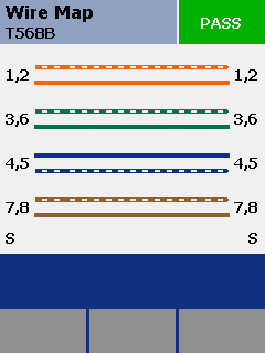
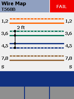
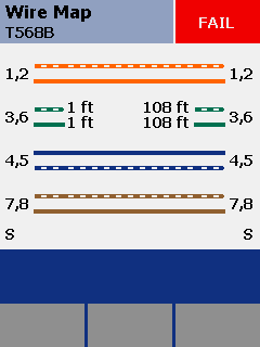
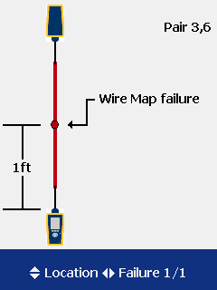
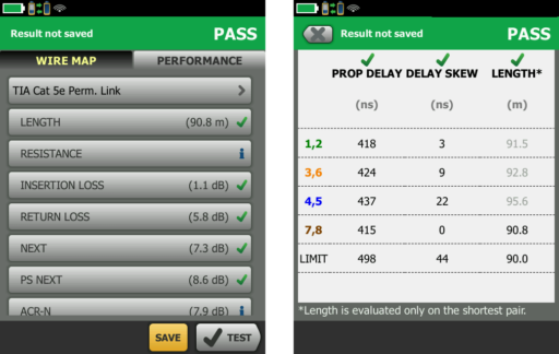
Wire Map Tests (Wiremap)
The wiremap test aims to verify the integrity of the connections of the four conductor pairs in a twisted pair cable, ensuring that each conductor is correctly connected in accordance with the standards.
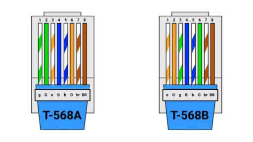
During this test, the eight conductors of the cable are evaluated to ensure compliance with normative specifications. The main aspects verified include:
- Pin-to-pin continuity;
- Short circuit;
- Pair transposition;
- Pair reversal;
Propagation Tests
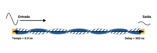
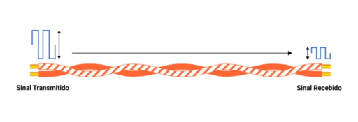
Propagation tests are used to evaluate the efficiency of signal transmission through a physical medium.
Propagation Delay refers to the time required for a signal to travel the full length of a cable from one end to the other, measured in nanoseconds (ns). This “delay” is one of the determining factors that limit the length of metallic cabling in a telecommunications network.
In networks that use collision detection protocols, such as Ethernet networks (the vast majority of networks), propagation delay must be controlled to prevent response times from being compromised. Standards define a maximum horizontal delay limit of 570 ns for cables up to 100 meters.
Since each pair in the network cable has its own unique twist rate, the delay will vary for each pair.
Delay Skew refers to this difference in propagation time between the fastest and the slowest pair in a twisted pair cabling system.
This variation must not exceed 50 ns in any link segment up to 100 meters.
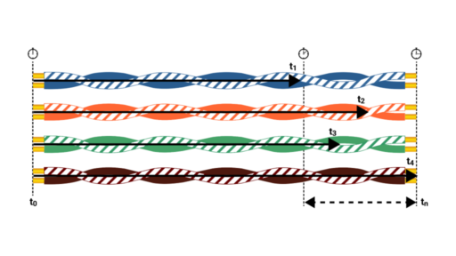
This difference can have a significant impact on data transmission, especially in transmissions that use all four pairs simultaneously, such as Gigabit Ethernet applications.
Although receiving devices are designed to tolerate small variations in propagation delay, an excessively large delay skew can make it impossible to correctly recombine the original signal.
Cable Length
Cable length measurements are calculated based on the propagation delay value.
This assessment is based on the Nominal Velocity of Propagation (NVP), generally expressed as a percentage (%) relative to the speed of light in a vacuum (300,000 km per second).
The NVP value is provided by manufacturers and typically ranges between 56% and 78%, depending on the design and materials used in the cable. This value is calculated based on the shortest pair within the cable jacket.
Acceptance criteria for cable length are based on the maximum limit allowed for the channel (100 m) or permanent link (90 m), plus a 10% uncertainty margin related to the NVP, as specified by the standards.
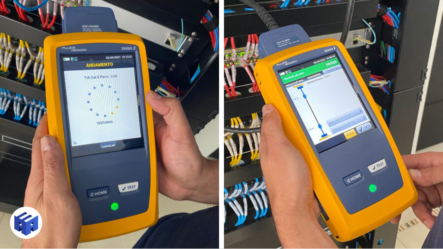
In the example below, the length (based on the shortest pair) exceeds the limit by 0.8 m, but still passes — due to the 10% rule.
Cable length is important for several reasons. The longer the cable, the greater the signal attenuation, making signals weaker and potentially leading to transmission errors and reduced data throughput.
An important consideration is that the length of the conductors inside the cable tends to be slightly longer than the linear cable length. This is due to the twisting of the wires, which serves to reduce electromagnetic interference and improve signal integrity.
In practice, the best approach is always to minimize the length of network cables. To this end, the network layout should be planned to position connection points as close as possible to the connected devices, avoiding unnecessarily long routes.
Conductor Resistance
Resistance is the measure of opposition to the flow of electrical current through a conductor. In structured cabling systems, conductor resistance must be within the limits established by the standards to ensure efficient data transmission.
The resistance of a cable is directly proportional to its length and inversely proportional to its cross-sectional area. This means that longer cables or cables with smaller diameter conductors will have higher resistance.
Resistance also increases with temperature, so cables operating in hotter environments will have elevated resistance. This is an important factor to consider in network design for high-temperature environments.
Resistance takes on even greater importance when considering PoE (Power over Ethernet) applications. In this context, a critical parameter is resistive balance — the difference in resistance between the two conductors of a pair in a cabling system.
Resistive imbalance can result in current inconsistencies in the cabling channel, which may cause saturation in the transformers of the Power Sourcing Equipment (PSE) and consequently compromise proper power delivery.
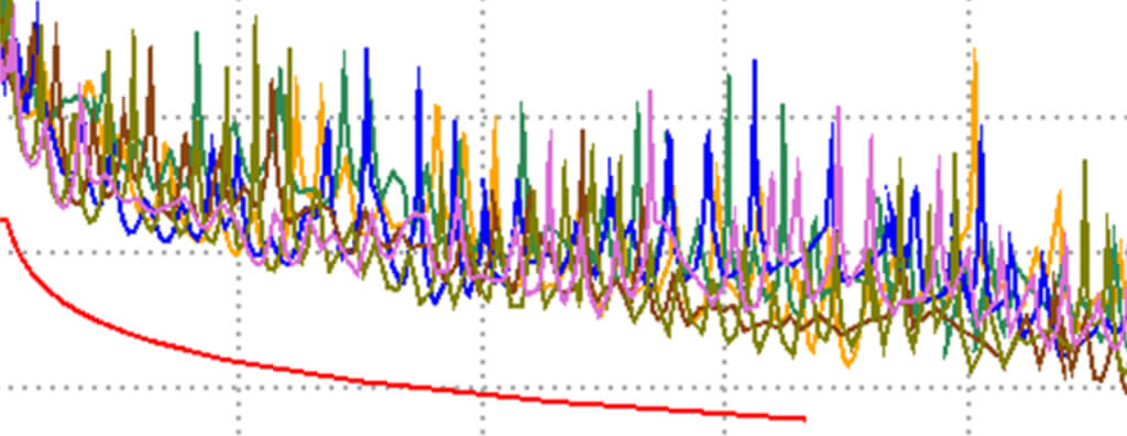
Signal Attenuation (Insertion Loss)
Insertion Loss refers to the attenuation that a signal undergoes as it propagates along a cable. It is expressed in decibels (dB) and indicates the amount of signal lost due to resistance, capacitance, and other forms of energy dissipation in the cable.
The insertion loss characteristics of a link vary with the frequency of the transmitted signal. Higher-frequency signals encounter greater resistance and therefore higher insertion loss.
Insertion loss must be measured across the applicable frequency range for the channel in question. For example, for a Category 5e channel, insertion loss must be checked for signals ranging from 1 MHz to 100 MHz. For Category 6 links, the frequency range is 1 MHz to 250 MHz.
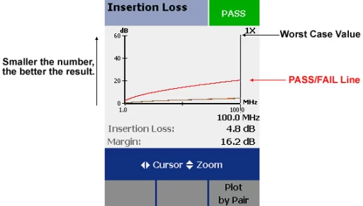
Insertion loss also increases approximately linearly with link length. This means that longer cables will have greater attenuation.
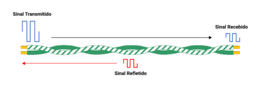
Return Loss
Return Loss is a measure that indicates the amount of signal reflected back to the transmitter due to discontinuities or imperfections in the transmission path. It is calculated from the ratio between the power of the transmitted signal and the power reflected back, and is expressed in decibels (dB).
A higher Return Loss value represents better system performance, since it means that a smaller proportion of the signal is being reflected back to the transmitter, resulting in more efficient signal transmission to the receiver.
Return Loss can be caused by physical damage to cables, such as kinks or crushing that introduce impedance discontinuities. In addition, improper termination practices — such as excessive untwisting of pairs during cable termination — can also compromise impedance uniformity and increase signal reflection.
Water infiltration is another significant source of Return Loss, as it alters the dielectric properties of the cable insulation, directly impacting its characteristic impedance and consequently increasing signal reflections.
Crosstalk
Crosstalk is a phenomenon that occurs when a signal transmitted on one wire pair interferes with another pair within the same cable. This can result in noise and signal degradation, affecting the quality of data transmission.
There are three main types of crosstalk commonly considered during the certification of a structured cabling network:
NEXT
NEXT, also known as near-end crosstalk, is a measure of the interference that occurs at the same end of the cable from which the signal is transmitted. In other words, it is the amount of signal that “leaks” from one wire pair to another at the point closest to the signal source.
The interference is caused by electromagnetic coupling between the wire pairs. When an electrical signal is transmitted through a pair, it creates a surrounding electromagnetic field.
If another wire pair is sufficiently close, this electromagnetic field can induce an electrical signal in that second pair, resulting in interference.
This measurement is expressed in decibels (dB) and represents the ratio between the injected signal and the noise level induced by interference. A higher dB value indicates better near-end crosstalk attenuation and therefore superior performance.
NEXT is particularly problematic in high-speed, high-frequency networks, where signals are more susceptible to interference. It can result in transmission errors and signal quality degradation, affecting network efficiency and reliability.
PSNEXT
PSNEXT (Power Sum Near-End Crosstalk) is a cumulative measure of the interference that occurs at the same end of the cable from which the signal is transmitted.
This metric is calculated by summing the individual NEXT effects from all other wire pairs at the point closest to the signal source.
In high-speed, high-frequency networks — such as Gigabit Ethernet, which supports 4-pair simultaneous transmission schemes — PSNEXT can be a more accurate indicator of signal quality than NEXT alone.
During the PSNEXT test, signals are injected into the different wire pairs of the cable while the interference in the receiving pairs is measured.
The objective is to evaluate the cumulative crosstalk level that a specific pair may experience when all other pairs are transmitting signals simultaneously.
PSNEXT measurement allows verification of the cabling’s ability to handle the electromagnetic interference resulting from simultaneous transmission across all pairs, thereby ensuring high-quality and reliable communication.
Signal-to-Noise Ratio
The Signal-to-Noise Ratio (SNR) is a metric expressed in decibels (dB) that quantifies the clarity of a signal relative to background noise.
In a structured cabling system, the signal-to-noise ratio is an important indicator of signal quality.
There are several forms of SNR commonly considered during the certification of a structured cabling network, including ACR-F (Attenuation to Crosstalk Ratio at Far-end) and PSACR-F (Power Sum ACR-F).
ACR-F
ACR-F, also known as ELFEXT (Equal Level Far-End Crosstalk), is a parameter that quantifies the difference between FEXT and the attenuation in the cable pair being analyzed.
By subtracting the signal attenuation in the pair in question from the measured far-end crosstalk, ACR-F provides a more precise measure of the interference caused by crosstalk, isolating it from the effects of signal attenuation.
This enables a more accurate assessment of cabling performance relative to crosstalk across different cable pairs.
PSACR-F
PSACR-F, also known as PSELFEXT (Power Sum Equal Level Far-End Crosstalk), follows the same principle as PS-NEXT: it is the sum of the ELFEXT effect of one pair on the other three pairs of the cable.
Like PS-NEXT, PSACR-F is an important measurement in installations that use all four pairs to transmit and receive data, as is the case with certain high-speed transmission standards such as Gigabit Ethernet.
PSACR-F takes into account the sum of the ELFEXT effect caused by a specific pair on the other three pairs of the cable.
This allows for the evaluation of the interference caused by crosstalk across all cable pairs, considering the interactions between them.
Through PSACR-F, a more comprehensive view of cabling performance with respect to crosstalk can be obtained, considering the combined effect of all cable pairs.
This helps ensure reliable, high-quality transmission in systems that use all pairs for data transmission.

Certification Equipment
Metallic cabling certification tests are performed with specialized equipment that ensures measurement accuracy and compliance with the required standards. One of the most widely used devices for this purpose is the Fluke Networks DSX CableAnalyzer, especially the DSX series. These devices are designed to perform all the tests mentioned quickly and reliably, following international certification standards.
The Fluke DSX series offers a range of features that make certification more efficient and precise. It is capable of testing and certifying twisted pair cables for applications up to 10 Gigabit Ethernet (10GBASE-T), and is widely used in corporate and industrial environments where network reliability is critical.
Source: A3A Systems Engineering
Purpose of Cabling Certification
Cabling certification has as its primary objective to ensure that the installation was carried out correctly and that the network delivers the expected performance according to the type of cable used. This certification verifies that the cabling supports the necessary transfer rate and provides the bandwidth defined in the project, ensuring that the network infrastructure meets speed and reliability requirements. In addition, certification is essential to prevent future problems such as packet loss or communication failures, guaranteeing that the network operates at maximum efficiency and without interruptions.
Bandwidth vs. Data Rate
Bandwidth
Bandwidth refers to the maximum capacity of a cable or transmission medium to carry signals, considering the frequency range it can support. It is measured in hertz (Hz) and indicates how many oscillations per second the cable can transmit. Simply put, the higher the bandwidth of a cable, the greater the volume of data it can theoretically carry at one time.
For example, a cable with greater bandwidth can support technologies that use higher frequencies, which is necessary for transmitting large amounts of data, such as in 10 Gigabit Ethernet networks.
Data Rate
Data rate refers to the actual amount of data that can be transmitted through the cable in a given period of time. It is measured in bits per second (bps) and depends not only on bandwidth but also on factors such as cable quality, interference, and the efficiency of connected devices.
Even if a cable has a large bandwidth, the data rate may be limited by physical or network configuration factors. Therefore, data rate is a more practical metric of how the cabling actually behaves in real-world use.
Conclusion
Cabling certification ensures that the designed bandwidth of the cable is sufficient to support the required data rate, guaranteeing that the network operates efficiently and reliably.
Acknowledgements
Thank you for reading our article on metallic cabling certification! If you need to ensure that your network infrastructure meets performance standards or are looking for specialized consulting for structured cabling projects, we are here to help.
A3A Systems Engineering offers comprehensive network certification services and technical support for projects, ensuring quality and efficiency for your Network infrastructure.