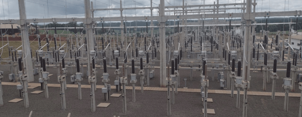
Learn how to structure telecommunications design for substations, including optical networks, teleprotection, SCADA, IEC 61850, redundancy, cybersecurity, testing, and commissioning.
Check it out!
A substation telecommunications design is not limited to deploying optical fiber or installing switches. It defines the physical and logical infrastructure that supports supervision, control, protection, operational voice, remote assistance, video monitoring, electronic security, time synchronization, and integration with control centers.
Remote assistance requires integration among operations, telecommunications, and monitoring. A solução precisa coordenar supervisão, comandos, contingência, comunicação, vídeo operativo e procedimentos de resposta conforme a aplicabilidade da instalação.
Learn about the Remote Assistance and Operational Monitoring solution
Communication infrastructure needs to originate from operational requirements. Arquitetura, redundância, fibras, equipamentos, alimentação e testes devem ser definidos a partir dos serviços que a subestação precisa manter disponíveis.
In utility and power-sector substations, a communication failure can compromise operational visibility, delay event identification, prevent event transmission, degrade remote assistance, or make resources used for operational coordination unavailable. Therefore, availability, redundancy, latency, segregation, power-supply, and recovery requirements need to be established during design.
The scope also needs to reflect the reality of each project. A distribution substation integrated with a utility control center has different needs from an installation covered by Brazil’s Operation Network, a strategically remote-assisted substation, or an expansion within an existing facility. ONS Grid Procedures are key references when applicable, but they do not replace corporate standards, technical specifications, automation philosophies, and each operator’s specific requirements.
This article explains how to structure, document, procure, and commission telecommunications projects for distribution and transmission substations, focusing on utilities, transmission companies, generators, EPC contractors, integrators, and companies responsible for modernizing existing facilities.
Why telecommunications is a critical substation discipline
Telecommunications infrastructure connects the electrical process to systems that allow the facility to be observed, controlled, recorded, and coordinated. It transports information among IEDs, relays, remote terminal units, local supervision and control systems, gateways, control centers, teleprotection equipment, servers, engineering workstations, and monitoring platforms.
This function requires treatment different from a conventional corporate network. Traffic flows have different criticalities, response times, and consequences. An administrative file, a security video stream, a status indication, and a protection-related message cannot be treated as equivalent traffic merely because they use Ethernet or fiber optics.
The design should establish which services may share infrastructure, which require logical segregation, which require physically independent paths, and which must maintain local operation if external communications are lost. It also needs to define how failures will be detected, recorded, communicated, and handled by operations and maintenance.
For installations covered by Brazil’s Grid Procedures, Submodule 2.15 classifies voice and data services according to availability requirements. Class A service, for example, has a total availability requirement of 99.98% and should use independent resources and routes. This classification should not be applied indiscriminately to every substation, but it demonstrates that architecture needs to be linked to the operational service and regulatory applicability.
Survey and requirements definition
The design begins before topology is drawn. It is necessary to understand the facility’s function, existing systems, interfaces with control centers, operator standards, services that will use the network, and physical implementation constraints.
Characterization of the facility and operations
The survey should identify whether the substation is locally staffed, remotely assisted, or prepared for future remote operation; whether it is part of Brazil’s Operation or Supervision Network; whether it is considered strategic; which centers interface with it; and which services need to remain available under normal, degraded, or contingency conditions.
The physical arrangement, yards, control houses, relay shelters, technical rooms, gatehouses, access routes, cable trenches, galleries, poles, cable entries, racks, optical distribution frames, available power supply, and environmental conditions are also evaluated.
Existing-system inventory and assessment
For modernization projects, the inventory should record equipment, models, firmware, ports, interfaces, protocols, fibers, terminations, addresses, VLANs, routes, power supplies, batteries, licenses, integrations, and support status. Old diagrams do not replace field verification.
The assessment should distinguish assets that can be retained, equipment that needs replacement, links with insufficient capacity, undocumented fibers, nonredundant topologies, and components lacking support or compatibility with the future architecture.
Service and criticality matrix
A service matrix relates each application to its source, destination, required availability, traffic volume, allowable latency, protocol, security, power supply, and contingency arrangements. This prevents the design from being reduced to an equipment list.
| Service | Typical source and destination | Requirements to be defined |
| Supervision and control | RTU, local supervision and control system, gateways, and control centers | data age, availability, protocol, integrity, and point-to-point testing |
| Teleprotection | relays and line terminals | transfer time, symmetry, availability, independence, and channel supervision |
| Substation automation | IEDs, switches, servers, and workstations | topology, priorities, synchronization, engineering, and recovery |
| Operational voice | facility and control center | service class, recording, contingency, and availability |
| Remote assistance | substation and remote center | supervision, commands, voice, video, redundancy, and degraded operation |
| Operational video surveillance | yard, rooms, and control center | useful resolution, latency, recording, availability, and event integration |
| Physical security | perimeter, access points, and security center | segmentation, retention, alarms, remote access, and response |
| Management and maintenance | equipment and administrative workstations | authentication, logs, access restrictions, and maintenance windows |
Services that use the communications infrastructure
Supervision, control, and data acquisition
SCADA systems depend on the acquisition of telemetering, status indications, alarms, events, and commands. The design needs to map data points from their origin in the process to the system that uses them, including transducers, IEDs, RTUs or local supervision and control systems, concentrators, gateways, WAN links, and control centers.
When Brazil’s Grid Procedures apply, Submodule 2.12 establishes requirements for data interconnections, information quality, data age, sequence of events, time synchronization, and connectivity tests. The document also distinguishes interconnections used for automatic generation control, traditional supervision and control functions, and sequence-of-events recording.
The telecommunications design needs to translate these functional requirements into capacity, topology, interfaces, redundancy, protocols, forwarding rules, and test criteria.
Teleprotection
Teleprotection uses communication channels to accelerate, block, permit, or coordinate operations between line terminals. Because the function is directly related to fault clearing, bandwidth alone is insufficient: transfer time, reliability, availability, symmetry, supervision, route independence, and behavior under failures need to be defined.
In a converged architecture, sharing physical media or equipment should be evaluated against protection requirements. VLANs do not create physical independence, and a single shared device can remain a single point of failure even when networks are logically separated.
Operational voice
Voice communications support pre-operation, real-time operation, post-operation, contingencies, and coordination among centers and facilities. The design should address terminals, recording, retention, availability, routes, numbering, integration with existing telephony, and behavior if the primary network is lost.
ONS Submodule 2.15 establishes voice-communication classes and configurations for situations covered by Brazil’s Grid Procedures. Submodule 2.16 provides for recording of operational communications and continuity requirements for control centers.
Time synchronization
Relays, IEDs, servers, RTUs, recorders, cameras, and event systems need to use a consistent time reference. Without synchronization, it becomes difficult to correlate protection operation, state changes, alarms, commands, video recording, and human intervention.
The design should define time sources, distribution, protocols, redundancy, antennas, protection, required accuracy, and monitoring. In applications covered by Submodule 2.12, local supervision/control systems and RTUs should maintain clock accuracy compatible with sequence-of-events requirements, and timestamps should use UTC.
Operational video, remote assistance, and security
Operational video and physical-security surveillance both use cameras, but they have different objectives. Operational video supports interpretation of facility conditions, confirmation of situations in the yard, or additional context during events. Physical-security video surveillance protects perimeters, access points, buildings, and assets against intrusion, vandalism, and other incidents.
The design should separate requirements for coverage, image quality, availability, retention, latency, integration, and operation. It is not appropriate to assume that every security camera can fulfill an operational function or that every facility requires visual confirmation of equipment.
Physical and logical architecture
The architecture should represent complete paths among field equipment, local systems, and remote centers. Conceptual diagrams alone are insufficient for implementation and acceptance.
Functional layers
A typical architecture can be organized into process, bay, station, WAN edge, and remote-center layers. At process and bay levels are IEDs, relays, acquisition interfaces, and devices associated with primary equipment. At station level are servers, gateways, RTUs or local supervision and control systems, operator workstations, core switches, and management systems.
This organization does not require a single technology. It helps identify where data are produced, processed, concentrated, recorded, and transmitted.
Segmentation by function and criticality
Segmentation should separate functions with different security and performance requirements. Protection, automation, supervision, video, physical-security, management, and supplier-access networks may require distinct zones and specific communication rules.
VLANs are a segmentation mechanism, but they need to be associated with traffic controls, access lists, firewalls, routing, authentication, monitoring, and documentation. A VLAN without inter-zone controls may merely reorganize traffic without effectively reducing exposure.
Physical paths and single points of failure
The design should represent ducts, cable trenches, poles, fibers, boxes, optical distribution frames, racks, switches, power supplies, and external links. Two links installed in the same cable, duct, box, or equipment do not constitute fully independent routes.
Single-point-of-failure analysis needs to consider civil infrastructure, power supply, converters, optical modules, switches, firewalls, routers, servers, licenses, and external dependencies. The objective is not to duplicate every component indiscriminately, but to align redundancy with the consequences of unavailability.
Optical networks and transmission media
Fiber optics is widely used in substations because it provides reach, capacity, electromagnetic immunity, and galvanic isolation. The design should define cable type, fiber count, routes, terminations, spare fibers, connectors, boxes, trays, identification, and test criteria.
OPGW, ADSS, and internal cables
OPGW can integrate communications with the shield wire on overhead lines; ADSS can be installed as a self-supporting cable in compatible applications; and internal dielectric cables can serve yards, control houses, galleries, and interbuilding links. Selection depends on environment, distances, mechanical loads, electric fields, available infrastructure, maintenance, and operator standardization.
The article Optical Networks in Substations: OPGW, ADSS, Topologies, and Testing examines these alternatives in greater depth.
Optical power budget and compatibility
Each link should have an optical power budget considering transmitters, receivers, fiber attenuation, connectors, splices, splitters, engineering margin, aging, and future interventions. Selecting a transceiver solely by the manufacturer’s nominal distance can result in links without adequate margin or received power above the allowable limit.
Wavelength, fiber type, connector, reach, temperature, encoding, speed, equipment compatibility, and spare availability also need to be verified.
Documentation and optical testing
Documentation should identify cable, fiber, source, destination, route, optical distribution frame, tray, port, splice, and spare capacity. Continuity, insertion-loss, and OTDR tests need to be planned according to the link and owner’s criteria.
Acceptance should not be limited to the statement that the link is up. A link may communicate even with excessive loss, poor splicing, improper bend radius, or incorrect documentation.
Redundancy, availability, and contingency
Availability should be treated as a measurable requirement. The design needs to define the service, evaluation period, maximum downtime, architecture, monitoring, maintenance, spares, and recovery.
For installations covered by Submodule 2.15, services may be classified as A, B, or C. Class A requires total availability of 99.98%, independent resources, and two independent routes; Class B requires availability of at least 99.00%. The same document establishes network-quality parameters such as latency, delay variation, and packet loss.
These values should be used only when the facility and service fall within the document’s applicability. In other distribution substations, the operator may adopt its own requirements, often equally stringent, according to its operational philosophy and the impacts of communication loss.
Local redundancy
Switches, power supplies, controllers, servers, and interfaces may have redundancy by duplication or intrinsically. The design should indicate how switchover occurs, which state is monitored, how long recovery takes, and how failure will be tested.
Route redundancy
Independent routes need to avoid common causes of failure. When two paths depend on the same cable entry, box, pole, power supply, equipment, or carrier, independence is partial and should be declared.
Degraded operation
Loss of the WAN should not necessarily interrupt essential local functions. The design needs to define what continues operating, which data are stored, how subsequent synchronization occurs, which commands are blocked, and when local operation should be assumed.
Integration with protection, automation, and SCADA
Telecommunications engineering should be coordinated with protection and automation from the outset. Changes in topology, timing, protocols, addressing, or synchronization can affect critical functions even when the network appears to remain available.
IEDs, RTUs, local supervision/control systems, and gateways
The design should define how IEDs connect, which data are concentrated, where protocol conversion occurs, which equipment maintains history, how communication states are supervised, and how information reaches local and remote systems.
For installations covered by Submodule 2.12, the data interconnection comprises the entire chain between the field measurement or command point and the control center. This includes RTUs or local supervision/control systems, concentrators, WAN links, and interface equipment.
IEC 61850 and communications engineering
The IEC 61850 series establishes models and services used in power-system automation. The design needs to coordinate data models, configuration files, communications engineering, addressing, publications, subscriptions, priorities, synchronization, and testing.
Documentation available in A3A Engenharia’s technical base includes ABNT NBR IEC 61850-10, dedicated to conformance testing. It covers methodologies for client devices, servers, sampled values, engineering tools, SCL files, GOOSE, redundancy, latency, and synchronization. This part does not replace the other parts of the series nor, by itself, demonstrate complete interoperability of an integrated system.
Interface management
Protection, automation, telecommunications, IT, electronic security, civil engineering, and operations need to share an interface matrix. This matrix records who supplies each signal, protocol, port, fiber, power supply, cabinet, software, license, configuration, test, and document.
Without this management, gaps often appear between supply packages: the manufacturer provides one port, the integrator expects another interface, the network does not permit the required protocol, and commissioning discovers the conflict only at the final stage.
Remote assistance, operational video, and switch monitoring
Remote assistance means providing support to facility operation from a remote location. It depends on supervision, command, communication, contingency resources, qualified personnel, and operating procedures. Cameras and sensors can complement situational awareness, but they do not replace protection systems, interlocks, electrical indications, or switching procedures.
For facilities in Brazil’s Operation Network covered by the document, Submodule 2.16 establishes requirements for local and remote assistance. Remote-assisted facilities should maintain local supervision and controls for degraded conditions, periodically test assistance resources and auxiliary power supplies, maintain a contingency plan, and adopt cybersecurity controls.
For strategic remote-assisted facilities, item 4.3.1 provides for continuous monitoring of the yard and control/protection rooms, as well as additional resources beyond the supervisory system for remote confirmation of opening and closing of disconnect switches used in real-time operational actions requested by ONS. This requirement is specific to the classification and applicability described in the document and should not be generalized to all substations.
The article Operational Video Surveillance in Substations details image, architecture, and integration requirements. The article Disconnect Switch Monitoring in Substations goes deeper into visual confirmation and the role of video as a complementary resource.
Cybersecurity and remote access
Connecting the substation to remote centers, suppliers, and corporate platforms expands the attack surface. The design needs to define zones, conduits, authentication, profiles, firewalls, logging, updates, remote access, administrative workstations, and vulnerability management.
Separation between operational and corporate networks
Integration with the corporate network should occur through controlled interfaces. Direct routes, devices with undocumented multiple interfaces, and permanent maintenance access can bypass planned segmentation.
Vendor and integrator access
Remote access should use individual identity, strong authentication, authorization, defined duration, logging, and revocation. Shared accounts and permanent tunnels reduce traceability and make secure support termination more difficult.
Hardening and lifecycle management
Switches, routers, firewalls, servers, gateways, cameras, and IEDs need secure configuration, minimum necessary services, controlled firmware, backups, inventory, and monitoring. The design should specify the requirements, while operating procedures define how they will be maintained throughout the lifecycle.
Power supply, grounding, and infrastructure
Communications availability depends on power supply. It is inconsistent to design redundant links powered by a single source or by circuits without supervision and compatible autonomy.
When Submodule 2.6 applies, telecommunications systems should have two independent battery and rectifier sets, each sized for the full load, with a minimum autonomy of ten hours after loss of AC power. The document also provides for power from independent circuits and automatic transfer without permanent paralleling of battery banks.
At other substations, values should be defined by the operator’s specifications and risk analysis. The principle remains: sources, autonomy, distribution, protection, and alarms need to be coordinated with the service availability requirement.
Metallic cables, shields, racks, antennas, and equipment should be integrated into the grounding and equipotential bonding system according to the architecture and applicable standards. Infrastructure should also consider electromagnetic compatibility, segregation, mechanical protection, drainage, fire protection, access, and maintenance.
Design documents and deliverables
A detailed design should enable procurement, supply, implementation, configuration, testing, and operation. The exact set varies by project, but it needs to cover physical, logical, and functional architecture.
| Deliverable | Expected content |
| Design narrative | objectives, assumptions, criteria, services, architecture, and scope limits |
| Survey and assessment | inventory, existing conditions, constraints, interferences, and recommendations |
| Architecture diagram | equipment, zones, levels, remote centers, and interfaces |
| Network diagram | switches, routers, firewalls, links, ports, and redundancies |
| Optical diagram | cables, fibers, optical distribution frames, splices, spares, source, and destination |
| Service matrix | source, destination, protocol, criticality, availability, latency, and contingency |
| Addressing plan | IP, VLANs, subnets, names, ports, and responsibilities |
| Interface matrix | supply packages, signals, protocols, connectors, power, tests, and documents |
| Technical specifications | functional, environmental, electrical, optical, cybersecurity, and management requirements |
| Bill of materials | equipment, modules, licenses, accessories, cables, terminations, and spares |
| Design calculations | bandwidth, optical power budget, autonomy, heat dissipation, and capacity |
| Test plan | inspections, FAT, SAT, point-to-point tests, failures, performance, and acceptance |
| Final documentation | As-Built, backups, configuration files, inventory, reports, and manuals |
Responsibility for configuration files, passwords, certificates, licenses, and backups should be contractually defined. Delivering only drawings and diagrams may leave the operator without the elements needed to maintain or rebuild the system.
Design stages
Preliminary study and survey
The first stage consolidates requirements, existing documents, site survey, inventory, interfaces, constraints, and risks. In multisite projects, an inadequate sample may hide important differences among substations.
Basic design
The basic design defines the concept, architecture, services, topologies, availability criteria, main equipment, infrastructure, interfaces, and estimated quantities. It should make it possible to evaluate alternatives and structure procurement.
Detailed design
The detailed design specifies routes, fibers, ports, diagrams, addressing, lists, reference configurations, power supply, installation, tests, and acceptance criteria. It should be coordinated with automation, protection, civil, electrical, security, and operations disciplines.
Procurement support and vendor expediting
The engineering team may analyze proposals, vendor drawings, deviation lists, integration documents, and test plans. This activity reduces the risk of acquiring equipment that is individually compatible but unsuitable for the complete system.
Implementation and change management
During construction, interferences and actual conditions may require changes. Changes need to be analyzed, approved, and incorporated into the documents. Informal field adjustments tend to reappear as maintenance problems and As-Built discrepancies.
FAT, SAT, testing, and commissioning
Commissioning should be defined during design. Each important requirement needs a verification method, an expected result, and evidence.
Factory testing
FAT can verify assembly, versions, power supplies, redundancy, configuration, interfaces, protocols, licenses, alarms, and simulated scenarios. For systems based on IEC 61850, device conformance certificates are important, but they do not replace integration testing of the configured system.
Site testing
SAT confirms installation, identification, power supply, grounding, fibers, performance, connectivity, synchronization, routes, failover, alarms, and communication with actual systems. Optical tests need to be linked to the fibers actually installed.
Point-to-point testing
Tests should follow the data from its origin to the operational destination. In applications covered by Submodule 2.12, connectivity and point-to-point tests are provided between local supervision/control systems or RTUs and control-center systems, in addition to timestamp verification when required.
Failure and contingency testing
The team should, in a controlled manner, cause loss of links, power supplies, interfaces, equipment, and services to verify detection, switchover, alarms, and recovery. A redundant architecture whose failures have never been simulated has no demonstrated performance.
How to procure a telecommunications design for substations
The procurement scope needs to define the type and number of facilities, survey scope, systems covered, operator standards, interfaces, available documents, design levels, meetings, reviews, procurement support, construction monitoring, commissioning, and technical responsibility.
Proposals should not be compared only by the number of drawings. A consistent scope needs to explain which surveys will be performed, which calculations and matrices will be produced, how coordination will occur, and how far the contractor will support testing and implementation.
Minimum information from the owner
The owner should provide, where available, diagrams, drawings, standards, service lists, inventory, automation philosophy, current architecture, cybersecurity requirements, interfaces with centers, schedule, access restrictions, and responsible parties for other disciplines.
Lack of documentation does not prevent the design, but it increases the need for surveys, testing, interviews, and field validation.
Criteria for evaluating the engineering firm
The evaluation should consider experience in critical facilities, multidisciplinary capability, knowledge of telecommunications and operations, survey methodology, interface control, deliverable quality, technical independence, and commissioning experience.
It is important to verify whether the firm can distinguish network design, automation integration, operational video, physical security, and remote assistance, avoiding generic solutions that treat every system as a simple IP device.
Inspection and Owner’s Engineering
Owner’s Engineering technically represents the owner during design, procurement, manufacturing, implementation, testing, and acceptance. The function does not replace manufacturers or contractors; it verifies compliance with scope, coordinates interfaces, analyzes deviations, and preserves the owner’s technical interests.
In substation telecommunications projects, OE can review documents, participate in meetings, analyze proposals, verify vendor drawings, witness or expedite FAT, inspect installation, follow testing, control punch-list items, and validate the final dossier.
This model is especially useful in programs involving multiple substations, where standardization, repeatability, and change management directly affect cost, schedule, and future maintenance.
Common mistakes
Starting with the equipment list
Defining switches, fibers, and servers before consolidating services, criticalities, and interfaces produces an architecture based on the catalog rather than operations.
Treating VLANs as sufficient redundancy or security
VLANs help segment traffic, but they do not eliminate single points of failure, create independent routes, or replace controls between zones.
Mixing operational video and physical-security surveillance
The two systems may share components or platforms, but they need their own objectives, image criteria, availability, retention, and operating requirements.
Ignoring power supply and civil infrastructure
Failures in power supplies, batteries, ducts, boxes, HVAC, or grounding can interrupt a logically redundant network.
Leaving testing until the end
When acceptance criteria do not appear in the specifications, suppliers may deliver equipment without preparing the environments, tools, files, and evidence needed for commissioning.
Generalizing ONS requirements
Brazil’s Grid Procedures have defined scope and applicability. They should be interpreted together with the facility classification and operator requirements, without turning specific provisions into universal obligations for every substation.
Technical basis for specifying and procuring the design
Before consolidating the terms of reference, architecture, and acceptance criteria, it is useful to examine the main subsystems that make up the substation telecommunications design.
- Operational telecommunications: voice, data, teleprotection, and redundancy
- Digital substation and IEC 61850
- Telemetry and SCADA integration
- DNP3
- IEC 60870-5-104
- RTUs in substations
- IEDs in substations
- PRP and HSR
- IEC 62443 and OT cybersecurity
- IEC 62351 and security of power-system protocols
These materials help transform generic requirements into verifiable criteria for topology, interoperability, redundancy, segmentation, synchronization, documentation, FAT, SAT, and commissioning.
Conclusion
Designing telecommunications for substations means converting operational needs into a verifiable physical and logical architecture. The work begins with service definition and ends only after links, equipment, integrations, redundancies, power supplies, security controls, and recovery procedures have been tested and documented.
For utilities and power-sector operators, the design also functions as a procurement and governance instrument. It defines responsibilities among protection, automation, telecommunications, security, IT, manufacturers, and implementation contractors; anticipates FAT and SAT criteria; and creates a consistent basis for inspection, Owner’s Engineering, commissioning, and lifecycle maintenance.
Technical references
[1] ONS. Submodule 2.15 — Minimum requirements for telecommunications.
[2] ONS. Submodule 2.12 — Minimum supervision and control requirements for operation.
[3] ONS. Submodule 2.16 — Operational requirements for control centers and Operation Network facilities.
[4] ONS. Submodule 2.6 — Minimum requirements for substations and their equipment.
[5] ABNT NBR IEC 61850-10 — Communication networks and systems for power utility automation — Part 10: Conformance testing.
Frequently asked questions
The scope may include surveying, service matrix, physical and logical architecture, optical networks, active equipment, operational voice, supervision and control, teleprotection, synchronization, remote assistance, video, cybersecurity, power supply, specifications, lists, test plans, and final documentation.
No. Brazil’s Grid Procedures have defined scope and applicability. The facility classification, its relationship to the Operation or Supervision Network, and the responsible operator’s specific requirements need to be verified.
Operational telecommunications support functions related to supervision, control, protection, voice, and operation of the power system. Their availability, timing, contingency, and security requirements may be more stringent and need to be linked to the consequences of failure.
No. VLANs are only part of segmentation. Routing controls, access lists, firewalls, authentication, security zones, monitoring, and physically independent paths may also be required.
When teleprotection schemes exist, the design needs to coordinate their channels, interfaces, timing, availability, redundancy, and supervision with protection engineering and the transmission media.
No. The IEC 61850 series addresses communications and models applied to power-system automation, but the design also needs to consider WAN, voice, teleprotection, video, security, management, optical infrastructure, power supply, and operator standards.
Video can provide situational awareness and, in specific situations, complementary visual confirmation. It does not replace electrical indications, protections, interlocks, supervisory systems, or operating procedures.
Depending on scope, testing may include inspection, optical tests, connectivity, point-to-point tests, protocols, synchronization, latency, loss, failover, power supplies, alarms, remote access, integration, FAT, SAT, and recovery after failures.
Yes, provided sufficient requirements and information exist. When documentation is incomplete, surveying, assessment, and interface validation normally need to be included before detailed design.
OE technically represents the owner, reviews documents, coordinates interfaces, analyzes deviations, follows procurement, FAT, implementation, testing, punch-list items, and final dossier validation.
Additional technical materials
- Solution — Remote Assistance and Operational Monitoring in Substations
- Service — Telecommunications Design
- Service — Commissioning and Acceptance
- Service — Integrated Electronic Security System Design
- Material — Operational Telecommunications in Substations
- Material — Optical Networks in Substations: OPGW, ADSS, Topologies, and Testing
- Material — Digital Substation and IEC 61850
- Related — Operational Video Surveillance in Substations
- Related — Disconnect Switch Monitoring in Substations
- Related — Substation Commissioning
