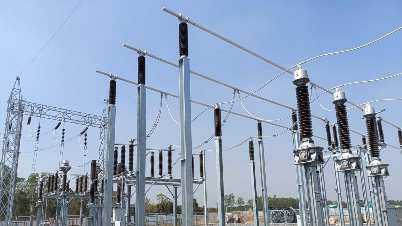
Technical criteria for selecting substation bus arrangements considering function, voltage level, bays, single-line diagrams, physical layout, reliability, maintenance availability, protection, studies, expandability, cost, and regulatory requirements.
Check it out!
The Role of the Substation in the Power System
A substation is an electrical node in the power system. Its functions may include voltage transformation, circuit switching, transmission-line connection, generation connection, supply of industrial loads, reactive compensation, metering, protection, and control.
From a system perspective, a substation is not merely a collection of equipment. It is the point where different parts of the electrical system are connected, isolated, protected, and operated. Therefore, substation topology directly influences supply continuity, restoration capability after faults, maintenance safety, and operational flexibility.
The higher the voltage, power involved, and systemic importance of the installation, the greater the availability requirement tends to be. In lower-criticality distribution substations, simple arrangements may be acceptable.
In transmission substations or strategic connection points, a fault in a busbar, circuit breaker, or transformer can cause significant load loss, operational restrictions, or system-wide impact. In these cases, more robust topologies become necessary.
What Is Substation Topology?
Substation topology is the way its circuits, busbars, circuit breakers, disconnectors, transformers, and other primary equipment are electrically connected. It defines the possible paths for power flow and the conditions for isolating equipment during normal operation, maintenance, or contingencies.
In practical terms, topology answers questions such as:
- how many busbars exist at each voltage level;
- how many circuit breakers are associated with each circuit;
- how a line, transformer, or feeder can be transferred between buses;
- what happens if a busbar fails;
- what happens if a circuit breaker fails;
- whether a circuit breaker can be taken out of service without disconnecting the circuit;
- how new bays can be added in the future.
Topology selection is not an isolated exercise. It is connected to Basic Design, electrical studies, protection philosophy, automation, physical arrangement, available area, budget, and the requirements of the utility, ONS, or industrial client.
Single-Line Diagram, Bus Arrangement, and Physical Layout
Three concepts are often used together but are not equivalent: the single-line diagram, the bus arrangement, and the physical layout.
Single-Line Diagram
The single-line diagram represents, in simplified form, the electrical connection among lines, transformers, busbars, circuit breakers, disconnectors, CTs, VTs, surge arresters, and other equipment. It is the main representation of the substation electrical topology.
The single-line diagram shows whether a substation uses a single bus, double bus, ring bus, breaker-and-a-half, or another arrangement. It also indicates metering, protection, grounding, and isolation points.
Bus Arrangement
The bus arrangement is the electrical configuration that defines how circuits connect to busbars and circuit breakers. It is a central part of substation topology, especially at high-voltage levels.
Single bus, double bus, main-and-transfer bus, ring bus, and breaker-and-a-half are all bus arrangements.
Physical Layout
The physical layout is the spatial implementation of the electrical topology. It defines the actual arrangement of equipment in the yard, in a medium-voltage room, or in a GIS substation. The layout must respect electrical clearances, access, vehicle circulation, maintenance areas, transformer removal, drainage, grounding, structures, cable trenches, buildings, cable routes, and operational safety.
The proper relationship among the three levels is:
substation function → single-line diagram → bus arrangement → equipment specification → protection and control → physical layout → operation and maintenance.
Elements That Make Up a Substation Arrangement
Before comparing topologies, it is necessary to understand the elements that make up the arrangement.
- Busbar: The busbar is the common connection node among circuits at the same voltage level. It may be rigid or flexible, air-insulated, gas-insulated, installed in medium-voltage switchgear, or used in hybrid arrangements. Electrically, the busbar must withstand rated current, short-circuit currents, electrodynamic and thermal stresses, and meet insulation and clearance requirements.
- Bay: A bay is the functional assembly associated with an incoming or outgoing substation circuit. It may be a line bay, transformer bay, bus-coupler bay, transfer bay, feeder bay, capacitor-bank bay, or reactor bay. Each bay normally includes switching, metering, protection, isolation, and grounding equipment. The number and position of these devices vary according to the topology.
- Circuit breaker: The circuit breaker interrupts load current and short-circuit current. In high-voltage arrangements, the number of circuit breakers per circuit is one of the main cost and reliability factors. In a single-bus arrangement, each circuit generally has one breaker. In a breaker-and-a-half arrangement, there are three breakers for every two circuits. In a double-bus double-breaker arrangement, each circuit has two breakers.
- Disconnector: The disconnector provides visible or functional isolation of equipment and circuit sections, but is not designed to interrupt short-circuit current. Its use is essential for maintenance, circuit transfer, bus selection, and operational safety.
- Earthing switch: The earthing switch allows isolated sections to be grounded for maintenance. Its application must be coordinated with electrical and mechanical interlocks to prevent improper switching.
- Current Transformers (CTs) and Voltage Transformers (VTs): Current and voltage transformers provide electrical quantities for metering, protection, control, and automation. Their location influences protection zones and must be consistent with the substation arrangement.
- Surge arresters: Surge arresters limit atmospheric and switching overvoltages. Their position in the physical and electrical arrangement must be defined based on insulation coordination and protection of major equipment.
Technical Criteria for Arrangement Selection
Bus-arrangement selection should result from a multi-criteria analysis. Lowest initial cost is rarely a sufficient criterion, especially in transmission substations, critical industrial installations, or generation connection points.
Service Continuity
The first criterion is the impact of a fault on supply. In a simple arrangement, a busbar fault may remove the entire substation from service. In more robust arrangements, the fault may be limited to one section or one circuit, or may not cause permanent interruption.
Operational Safety
The topology must allow safe switching, equipment isolation, grounding of sections under maintenance, and system restoration after contingencies. Operational safety also depends on arrangement clarity, interlocking logic, and simplicity of operation.
Maintenance Availability
An arrangement must be assessed not only under normal conditions but also during scheduled maintenance. The technical question is: which circuits must be disconnected to remove a circuit breaker, disconnector, busbar, CT, or transformer from service?
More sophisticated topologies exist precisely to reduce downtime during maintenance. In critical installations, the ability to keep circuits energized while circuit breakers or busbars are maintained may justify the higher cost.
Operational Flexibility
Operational flexibility is the ability to transfer circuits, change bus configurations, isolate sections, and operate in degraded conditions without significant load loss or system restriction.
This characteristic is relevant in substations that may have multiple sources, multiple outgoing circuits, parallel transformers, transmission interconnections, or planned future expansion.
Selectivity and Protection
More complex arrangements require more elaborate protection schemes. Bus differential protection, breaker-failure protection, reclosing, synchronism, selectivity among zones, and transfer logic must be compatible with the selected topology.
A robust arrangement without adequate protection may not deliver the expected performance. Therefore, topology and protection philosophy must be defined in an integrated manner.
Short-Circuit Capability
Topology influences short-circuit levels and current-contribution paths. Selection of circuit breakers, busbars, CTs, disconnectors, grounding grid, and structures must consider present and future short-circuit levels.
Expandability
Many substations are implemented in stages. The initial arrangement should allow evolution toward the final configuration without excessive rework, prolonged outages, or premature equipment replacement.
Available Area and Construction Technology
AIS substations require more area and clearances. GIS or hybrid substations reduce space but increase specialization in design, assembly, and maintenance. Construction technology should be analyzed together with the topology, not as a substitute for it.
Total Cost
The cost of an arrangement is not limited to the number of circuit breakers. It must include disconnectors, CTs, VTs, structures, foundations, busbars, cables, protection, automation, civil works, land, commissioning, maintenance, and the cost of unavailability.
Applicable Standards and Regulatory Requirements
In Brazil, projects connected to the transmission system must observe ONS technical requirements, in addition to ABNT, IEC, and IEEE standards and the specifications of the transmission company, distribution utility, or accessing agent. In general terms, minimum substation requirements treat the bus arrangement as an installation-performance item.
For air-insulated substations at certain voltage levels, ONS documents indicate reference arrangements such as double bus with single breaker at 230 kV and double bus with breaker-and-a-half for voltages equal to or above 345 kV, while allowing alternatives when studies demonstrate equal or superior performance in reliability, flexibility, and availability.
This requirement is relevant because it limits purely economic selection. In a transmission installation, topology must be demonstrated through studies including power flow, short circuit, busbar capacity, insulation coordination, switching transients, grounding, protection, and contingency analysis.
Main Bus Arrangements
The arrangements below are presented in increasing order of technical complexity and, in general, cost and availability.
Single Bus
The single-bus arrangement is the most basic configuration. All circuits connect to one busbar, generally through one circuit breaker and associated disconnectors.
Its main advantages are simplicity, low cost, smaller footprint, fewer devices, and straightforward operation. It is therefore common in smaller substations, simple industrial installations, distribution systems, and applications in which total or partial interruption is technically acceptable.
The main limitation is low availability. A busbar fault may disconnect all connected circuits. In addition, busbar maintenance normally requires total or significant shutdown of the installation. Maintenance of a circuit breaker may also require taking its circuit out of service.
| Aspect | Technical Assessment |
| Reliability | Low, because the busbar is a common failure point. |
| Maintenance | Limited; interventions may require shutdowns. |
| Flexibility | Low. |
| Cost | Lowest among classic arrangements. |
| Typical application | Distribution, low-criticality industry, and simple substations. |
Sectionalized Single Bus
A sectionalized single bus divides the busbar into two or more sections, normally by means of a bus-coupler or sectionalizing breaker. This division reduces the impact of faults and provides some operational flexibility.
If a fault occurs in one bus section, another may remain in service, depending on protection selectivity and circuit configuration. Loads and sources can also be distributed among sections to improve continuity.
This arrangement is a natural evolution of the single bus and is commonly adopted when improved availability is required without moving to a more complex topology.
| Aspect | Technical Assessment |
| Reliability | Medium; a fault can be limited to one section. |
| Maintenance | Better than a single bus, but still limited. |
| Flexibility | Medium. |
| Cost | Low to medium. |
| Typical application | Distribution, subtransmission, and industrial installations with segregable loads. |
Main-and-Transfer Bus
The main-and-transfer-bus arrangement adds an auxiliary bus used to temporarily transfer a circuit during maintenance of its main circuit breaker. In general, a transfer breaker can assume the function of the breaker of a specific circuit.
The technical benefit lies in circuit-breaker maintenance. Instead of disconnecting the circuit for breaker maintenance, it can be transferred to the transfer bus and kept in service through the transfer breaker.
The limitation is that the main bus can still be a critical point. A fault on the main bus may affect multiple circuits. Transfer operations also require clear procedures and adequate interlocks.
| Aspect | Technical Assessment |
| Reliability | Medium. |
| Maintenance | Good for circuit-breaker maintenance. |
| Flexibility | Medium. |
| Cost | Medium. |
| Typical application | Substations where breaker maintenance without circuit shutdown is relevant, but a more robust topology is not justified. |
Double Bus with Single Breaker
In a double-bus single-breaker arrangement, there are two main busbars and each circuit has one circuit breaker. By means of disconnectors, the circuit can be connected to either bus.
This arrangement increases operational flexibility because circuits can be distributed between buses and one bus can be taken out of service for maintenance, provided switching is properly planned. It also reduces the impact of busbar maintenance compared with a single bus.
The limitation is that each circuit still depends on a single breaker. Maintenance of that circuit breaker may require taking the circuit out of service unless additional transfer features are incorporated.
| Aspect | Technical Assessment |
| Reliability | Medium to high, depending on operating philosophy. |
| Maintenance | Good for busbars; limited for the circuit breaker. |
| Flexibility | High. |
| Cost | Medium to high. |
| Typical application | Transmission and subtransmission substations, especially where flexibility between buses is required. |
Double Bus with Three- and Four-Disconnector Arrangements
The terms double bus with three disconnectors and double bus with four disconnectors refer to variations in physical and functional arrangement in which each circuit has specific combinations of disconnectors for bus connection, breaker isolation, and, where applicable, transfer.
In practice, the number and position of disconnectors determine switching flexibility, the ability to isolate equipment, and safety during maintenance. The four-disconnector double-bus arrangement is especially relevant in transmission applications requiring greater switching capability and compliance with continuity requirements.
These variations must be analyzed together with the installation’s operating philosophy, bus differential protection, interlocks, and maintenance procedures.
Ring Bus
In a ring-bus arrangement, circuit breakers are connected to form a closed loop. Line, transformer, or feeder circuits are connected between two adjacent breakers. Thus, each circuit can remain connected to the system through alternative paths depending on operating conditions.
The main advantage of the ring bus is good reliability with a relatively efficient number of breakers. A breaker can be maintained with less impact on circuits, and a fault can be isolated without losing the entire substation.
However, the ring arrangement has expansion limitations. As the number of circuits increases, the ring becomes operationally more complex and may require evolution to another configuration, such as breaker-and-a-half.
| Aspect | Technical Assessment |
| Reliability | High for a limited number of circuits. |
| Maintenance | Good. |
| Flexibility | Good, but with limited expansion. |
| Cost | Medium to high. |
| Typical application | Transmission substations with few circuits and continuity requirements. |
Breaker-and-a-Half
The breaker-and-a-half arrangement is one of the most widely used topologies in high-criticality transmission substations. It has two main buses and three circuit breakers for every two circuits. Each circuit is associated with one dedicated breaker and shares a center breaker with the adjacent circuit.
This configuration provides high reliability and flexibility. A busbar fault or maintenance generally does not result in loss of the circuits. Circuit-breaker maintenance can also be performed with reduced impact, provided operation is properly planned.
Its cost is higher than arrangements with one breaker per circuit, but lower than a double-bus double-breaker arrangement. Breaker-and-a-half is therefore frequently adopted as a balance among reliability, cost, and complexity at higher voltage levels.
From a protection standpoint, the arrangement requires particular attention to protection zones, breaker-failure protection, current measurement in the branches, and tripping logic for the breakers associated with each circuit.
| Aspect | Technical Assessment |
| Reliability | Very high. |
| Maintenance | High availability during maintenance. |
| Flexibility | High. |
| Cost | High. |
| Typical application | Critical transmission substations, especially at higher voltages. |
Double Bus with Double Breaker
In a double-bus double-breaker arrangement, each circuit has two circuit breakers, normally one associated with each bus. This configuration provides high independence between buses and circuits.
The main advantage is maximum availability. Maintenance of a breaker or bus can be performed with minimal impact on the circuit. A busbar fault also tends not to remove the circuit from service as long as the other path remains available.
The disadvantage is high cost due to the number of circuit breakers, CTs, disconnectors, structures, protection systems, and required area. It is therefore adopted in extremely critical installations, generating plants, strategic interconnections, or points where unavailability has a very high system or economic impact.
| Aspect | Technical Assessment |
| Reliability | Maximum among classic arrangements. |
| Maintenance | Excellent. |
| Flexibility | Excellent. |
| Cost | Very high. |
| Typical application | Strategic points, critical generation, and substations with extreme continuity requirements. |
Arrangements in AIS, GIS, and Hybrid Solutions
AIS, GIS, and hybrid solutions are not, by themselves, bus arrangements. They are construction technologies.
In an AIS substation, equipment is air-insulated and generally installed in an outdoor yard. In a GIS substation, equipment is enclosed and gas-insulated, enabling a substantial reduction in area. Hybrid solutions combine compact modules with conventional sections.
The electrical topology may be similar in AIS or GIS. A GIS substation can have a double bus, breaker-and-a-half, or another configuration. What changes are aspects of area, maintenance, interfaces, cost, spare-parts availability, operation, assembly, and testing.
Technical Comparison of Arrangements
| Arrangement | Reliability | Maintenance | Flexibility | Relative cost | Typical application |
| Single bus | Low | Low | Low | Very low | Distribution and simple industry |
| Sectionalized single bus | Medium | Medium | Medium | Low to medium | Distribution, subtransmission, and segregable loads |
| Main-and-transfer bus | Medium | Good for breakers | Medium | Medium | Substations requiring circuit-breaker maintenance without shutdown |
| Double bus with single breaker | Medium to high | Good for busbars | High | Medium to high | Transmission and subtransmission |
| Ring bus | High | Good | Good | Medium to high | Transmission with few circuits |
| Breaker-and-a-half | Very high | High | High | High | High-criticality transmission |
| Double bus with double breaker | Very high | Very high | Very high | Very high | Critical generation and strategic nodes |
This comparison should be used as a conceptual reference. Final selection depends on electrical studies, operating philosophy, regulatory requirements, and life-cycle economic analysis.
How to Select the Arrangement According to Substation Application
Distribution Substations
In distribution substations, selection usually prioritizes simplicity, cost, ease of operation, and sectionalizing capability. Single-bus and sectionalized single-bus arrangements are common, especially when the distribution system provides redundancy or loads can be transferred through feeder networks.
When the substation supplies critical loads or has multiple transformers, a sectionalized bus tends to be more suitable because contingencies can be limited to part of the installation.
Industrial Substations
In industrial installations, the decision depends on the cost of process downtime. In continuous-process plants such as mining, oil and gas, pulp and paper, steel, or data centers, electrical unavailability may cause losses exceeding the additional CAPEX of a more robust arrangement.
In these cases, the analysis should consider load criticality, selectivity, transformer redundancy, transfer capability, maintenance without shutdown, and restoration philosophy.
Transmission Substations
In transmission, topology must meet system-performance requirements. Selection is conditioned by voltage, number of circuits, connection to the SIN, ONS requirements, N-1 contingencies, breaker failure, busbar maintenance, and future expansion.
At higher voltages, arrangements such as double bus and breaker-and-a-half become more common because they reduce the impact of faults and provide greater operational availability.
Generation Substations
Generation step-up substations must consider the unavailability associated with loss of generating units or generation blocks. In large plants, the topology should allow maintenance of bays, step-up transformers, transmission lines, and busbars with minimum impact on generated energy.
Switching Substations
Switching substations primarily interconnect circuits and enable system reconfiguration. Because voltage transformation is not necessarily present, the bus arrangement takes an even more central role. Flexibility, bus protection, and restoration capability are decisive criteria.
Studies Required to Validate the Selected Topology
The arrangement definition must be supported by technical studies. Depending on the size of the installation, these studies form part of Basic Design, the grid-access process, conformity analysis, and equipment specification.
Power Flow
The power-flow study verifies loading, voltage profiles, and power circulation among busbars, transformers, lines, and compensators. It makes it possible to assess whether the topology supports the expected operating scenarios.
Short Circuit
The short-circuit study determines maximum and minimum fault currents and supports specification of circuit-breaker interrupting capacity, thermal and dynamic withstand of equipment, and grounding-grid requirements.
Busbar and Equipment Ratings
Busbars, disconnectors, CTs, VTs, cables, connectors, and structures must be specified for rated current, short-time current, mechanical stresses, and environmental conditions.
Protection and Selectivity
The protection philosophy must be compatible with the topology. In arrangements with multiple buses or multiple circuit breakers per circuit, definition of protection zones and tripping logic is critical.
Breaker Failure
Breaker-failure analysis evaluates the effects of a circuit breaker that fails to open when commanded. In arrangements such as ring bus and breaker-and-a-half, this assessment is essential for defining which adjacent breakers must trip and which circuits will be affected.
Contingencies and Maintenance
The topology must be tested under scheduled-maintenance and contingency scenarios. The central question is: does the installation continue to meet its requirements when a busbar, circuit breaker, transformer, or line is unavailable?
Switching Transients and Insulation Coordination
Switching of lines, transformers, reactors, and capacitor banks can generate overvoltages. The arrangement and location of surge-protection equipment must be consistent with insulation-coordination studies.
Grounding
The grounding grid must address fault currents, touch and step voltages, transferred potential, and integration with structures, fences, cable trenches, shield wires, neutrals, and screens.
Layout and Expansion
Final validation must verify that the topology fits the site, that maintenance access is available, transformers can be removed, space exists for new bays, and phased implementation is feasible.
Common Errors in Defining Substation Arrangements
Selecting Only by Lowest CAPEX
The lowest initial cost may result in low availability, higher maintenance cost, and substantial losses from interruptions. The correct criterion is technical-economic cost, considering the life cycle and the impact of unavailability.
Ignoring Future Expansion
A topology suitable for the initial stage may be unsuitable for the final stage. When expansion is not planned, the installation may require complex interventions, long outages, and equipment replacement.
Underestimating Busbar Failure
Busbar faults are less frequent than faults in some equipment, but their impact can be severe. Analysis should consider the extent of load loss and the possibility of restoration.
Failing to Assess Circuit-Breaker Maintenance
Circuit breakers require inspections, tests, and maintenance. In simple arrangements, maintenance may take circuits out of service. In critical installations, this may be unacceptable.
Confusing GIS with Topology
GIS is a construction technology. The electrical topology still needs to be defined. A GIS may use a single bus, double bus, breaker-and-a-half, or another arrangement.
Failing to Coordinate the Single-Line Diagram, Protection, and Layout
A single-line diagram may appear technically adequate but create difficulties in layout, protection, maintenance, or expansion. The definition must be integrated from the early design phases.
Relationship with Automation, Supervision, and Remote Assistance
Substation arrangements also affect automation. The more complex the topology, the greater the need for reliable circuit-breaker and disconnector status indications, interlocks, synchronism, event records, oscillography, remote supervision, and integration with SCADA systems.
In modern substations, operation of the topology depends on a protection, control, and supervision architecture capable of correctly representing the installation configuration in real time. This includes alarms, measurements, commands, blocks, permissives, and switching sequences.
For further detail on the supervision layer, see A3A’s article on SCADA in the power sector and the content on remote assistance in substations.
Conclusion
Selecting a substation arrangement is a system-level decision. It should not be based only on tradition, lowest cost, or repetition of a standard configuration. It should result from analysis of the installation function, voltage, criticality, regulatory requirements, maintenance, probable failures, future expansion, protection, automation, and total cost.
Technically, the evolution of arrangements follows a clear logic: the single bus prioritizes simplicity and cost; the sectionalized bus improves continuity; the transfer bus reduces maintenance impacts; the double bus increases flexibility; the ring bus creates alternative paths; breaker-and-a-half provides high availability with balanced cost for transmission; and the double-breaker arrangement maximizes reliability in critical applications.
Therefore, the best arrangement is not necessarily the most robust, but the one that meets the reliability level required by the system, allows safe maintenance, supports future expansion, and is technically and economically justified.
Technical References
[1] ONS — Guidelines for Preparing Basic Designs for Transmission Projects
[2] ONS — Grid Procedures, Submodule 2.6: minimum requirements for substations and their equipment
[3] USDA Rural Utilities Service — RUS Bulletin 1724E-300, Design Guide for Rural Substations
Frequently Asked Questions
The simplest arrangement is the single bus. It has low cost and straightforward operation, but provides lower availability because a busbar fault can affect all connected circuits.
Among classic arrangements, the double bus with double breaker provides the highest availability because each circuit has two connection paths. Breaker-and-a-half also provides high reliability and is often more balanced in cost and performance for transmission.
Breaker-and-a-half is suitable for high-criticality transmission substations, especially at higher voltage levels, when circuit breakers and busbars must be maintained with low impact on the circuits.
In a double-bus single-breaker arrangement, each circuit has one breaker and can be connected to either bus. In breaker-and-a-half, there are two main buses and three breakers for every two circuits, increasing availability and operational flexibility.
Not necessarily. GIS is a construction technology using enclosed gas-insulated equipment. The electrical topology may still be single bus, double bus, breaker-and-a-half, or another arrangement.
No. The best arrangement is the one that meets the technical requirements of the installation at a justified cost. Using an excessively complex topology in a simple application can increase CAPEX, maintenance, and complexity without proportional benefit.
