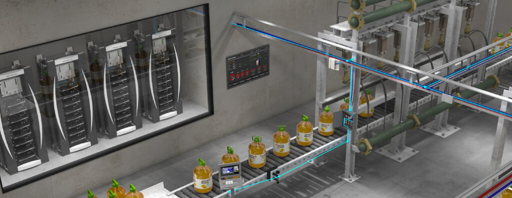
Industrial structured cabling according to NBR 16521:2025: MICE, IHD, ID, IO, MPTL, copper, fiber, pathways, EMC, certification, and retrofit.
Check it out!
Structured cabling for industrial environments must be designed according to environmental conditions, automation and ICT architecture, operational criticality, and the performance requirements of each area. The specific Brazilian reference is ABNT NBR 16521:2025, which addresses balanced and optical cabling in industrial installations and introduces elements such as the intermediate distributor (ID), industrial horizontal distributor (IHD), industrial outlet (IO), intermediate backbone, and MICE environmental classification.
It is not technically correct to address an industrial environment simply by choosing shielded cable, metallic cable tray, or optical fiber. The design must classify environments, select compatible components, define pathways and spaces, verify distances, interfaces, remote powering, equipotential bonding, testing, documentation, and maintenance strategy. It is also necessary to recognize the limits of NBR 16521: cabling intended for critical automation, process control, and monitoring applications may require additional criteria outside the scope of the standard.
What changed with NBR 16521:2025
The second edition of ABNT NBR 16521 was published on March 11, 2025, and replaced the 2016 edition. It consolidates industrial structured cabling as a system in its own right, compatible with the general architecture of NBR 14565 but adapted to industrial environments and interfaces.
The standard specifies:
- structure and minimum configuration of industrial cabling;
- interfaces at the industrial outlet;
- link and channel performance;
- component implementation requirements;
- environmental performance;
- verification procedures;
- balanced cabling, optical cabling, and applications with remote powering;
- MPTL configurations and direct connection in specific situations;
- single-pair balanced cabling for SPE under defined conditions.
It directly references NBR 14565, NBR 16415, NBR 16869-1, NBR 16869-3, NBR 16869-5, and NBR 17040, among other standards.
<div class="wp-block-a3a-destaque"><p>In an industrial plant, defining cable, connector, or shielding before classifying the environment and mapping applications often transfers risk to the construction phase. Industrial Structured Cabling Design translates MICE, topology, pathways, performance, interfaces, and acceptance criteria into verifiable requirements.</p><p><a href="https://a3aengenharia.com.br/servicos/planejamento/projeto-de-cabeamento-estruturado/">Structured Cabling Design</a></p></div>
Industrial cabling is not simply an Ethernet network in a harsh environment
The infrastructure may serve ICT, automation, monitoring, and industrial devices, but the architecture must respect the function of each link. NBR 16521 distinguishes between a telecommunications outlet (TO), used for ICT applications, and an industrial outlet (IO), used for industrial applications.
It also distinguishes structured cabling from the active industrial network. Protocols, industrial switches, logical redundancy, and automation behavior are not defined by the cabling standard. The passive layer must provide an appropriate physical medium; the active network architecture remains a separate design discipline.
This boundary prevents a common error: drawing a ring of switches and calling the active topology the “structured cabling topology.” They are different layers.
The four possible industrial cabling subsystems
NBR 16521 recognizes up to four subsystems:
| Subsystem | Origin/destination | Function |
| Campus backbone | CD → BD | interconnects buildings |
| Building backbone | BD → ID | vertical/building distribution |
| Intermediate backbone | ID → IHD | brings distribution closer to industrial areas |
| Industrial horizontal | IHD → IO/TO | serves devices and final areas |
The intermediate backbone is optional and represents an important difference from the conventional commercial model. It allows distribution to be brought closer to production areas without requiring all horizontal cabling to originate from a distant room.
ID, IHD, and IO: elements that must appear in the design
The intermediate distributor (ID) receives the building backbone and feeds one or more industrial horizontal distributors. The IHD originates industrial horizontal cabling. The IO is the termination point intended for the industrial device.
These elements may be located in rooms, racks, enclosures, panels, or industrial frames, provided the space and components are suitable for the corresponding environmental classification.
The documentation should clearly show:
- location of ID and IHD;
- associated cables and fibers;
- IOs and TOs;
- routes;
- cross-connections and interconnections;
- consolidation points when used;
- equipment and test interfaces;
- identification of each link.
MICE: environmental classification should drive the specification
MICE stands for Mechanical, Ingress, Climatic/Chemical, and Electromagnetic. The classification considers mechanical severity, contaminant ingress, climatic/chemical conditions, and the electromagnetic environment.
The same industrial building may contain areas with different classifications. Electrical rooms, laboratories, internal offices, process areas, pump houses, and production lines should not automatically receive the same cable and connector.
| Dimension | Examples of influence | Design impact |
| M — mechanical | vibration, impact, crushing | cable, pathway, connector, protection |
| I — ingress | dust, water, particles | enclosure, sealing, connectivity |
| C — climatic/chemical | temperature, oil, chemical agents | jacket, material, service life |
| E — electromagnetic | motors, drives, busbars | route, separation, shielding/fiber |
The solution may combine a more robust component with a protective pathway. It is not always necessary for every component to have the highest severity rating if the physical infrastructure reduces exposure.
Classify by section, not by the entire plant
NBR 16521 recognizes that an industrial environment may be severe throughout or only in certain sections. Therefore, classification should follow the route of the channel.
A cable may leave a clean room, cross an area with drives and motors, and terminate at a panel exposed to dust. The design must identify where severity changes and ensure each segment remains compatible with installation conditions.
This approach avoids two extremes: underspecifying critical sections or overspecifying the entire plant.
Industrial horizontal cabling: limits and configuration
The industrial horizontal subsystem connects the IHD to IOs or TOs. The cable must be continuous between the IHD and IO/TO, except when a consolidation point is used within the permitted architecture.
For conventional balanced cabling, the physical reference remains:
- up to 90 m of fixed industrial cable;
- up to 100 m of total physical channel;
- up to 10 m combined cord length in reference implementations;
- patch cords/jumpers at the IHD limited according to the standard implementation.
NBR 16521 also recognizes special single-pair Ethernet configurations with their own limits, which must not be confused with the conventional four-pair channel.
Temperature can reduce the allowable length
Industrial environments often operate above 20 °C. NBR 16521 establishes reductions in industrial-cable length for temperatures above this value in reference implementations:
- shielded cable: 0.2% reduction per °C;
- unshielded cable between 20 °C and 40 °C: 0.4% per °C;
- unshielded cable above 40 °C up to 60 °C: 0.6% per °C.
Therefore, automatically designing 90 m of cable in a hot area can eliminate channel margin. Temperature must be included in the design calculation.
Performance category and class
NBR 16521 maintains the relationship between component categories and cabling classes:
| Components | System class |
| Category 5e | Class D |
| Category 6 | Class E |
| Category 6A | Class EA |
| Category 7 | Class F |
| Category 7A | Class FA |
| Category 8.1 | Class I |
| Category 8.2 | Class II |
Mixing components from different categories reduces the resulting performance to the lowest compatible category. Therefore, “Cat6A cable” does not create a Class EA channel if connectors, patch cords, or hardware do not meet the same performance level.
Cat6A, shielding, and the industrial environment
Cat6A can be an appropriate choice for 10GBASE-T over 100 m and for designs with a longer capacity horizon, but it is not an automatic solution to interference. Shielding and category are different characteristics.
A cable can be Cat6A U/UTP or shielded Cat6A. The choice among U/UTP, F/UTP, U/FTP, S/FTP, or other constructions should consider MICE, coupling performance, pathways, equipotential bonding, connectivity, and maintenance.
Poorly terminated shielding or shielding without continuity may not deliver the expected behavior. The system must be analyzed as a channel.
When optical fiber is the better decision
Optical fiber provides immunity to electromagnetic interference in transmission and is especially useful for backbone, long distances, interbuilding areas, and zones near intense noise sources.
This does not mean every fiber cable is automatically suitable for the environment. Optical cables have mechanical construction, jackets, resistance to external agents, and metallic elements that must be compatible with the installation.
The design should define:
- single-mode or multimode according to the application;
- fiber count;
- connectivity;
- optical distribution frames;
- loss budget;
- routes and mechanical protection;
- reserves;
- test method.
NBR 16521 recommends LC duplex connectivity at the IO and recognizes 12- or 24-fiber MPO for high-density applications.
Industrial connectors: RJ45 is not the only interface
The standard recognizes eight-position modular connectivity for several categories as well as specific industrial interfaces. The eight-contact M12 connector is recognized for Class EA under applicable conditions, and single-pair connectors according to IEC 63171-6 are included for SPE.
The interface must be selected according to the application and environment. An office-grade RJ45 inside a panel exposed to vibration, dust, or liquids may be unsuitable even if it has the required electrical category.
IO versus MPTL
When the application does not support a conventional industrial outlet or when direct connection to the device is more appropriate, NBR 16521 allows an MPTL configuration in accordance with NBR 16869-3.
In MPTL, the horizontal cable terminates with a modular plug and connects directly to the equipment. This reduces connection points but changes the test model and termination management.
The decision must be documented and not applied as a field improvisation.
Consolidation point in an industrial area
The CP is optional and can facilitate relocation of IOs or TOs in open industrial spaces. As in commercial environments, it must be accessible, documented, and used within the architectural limits.
A CP is not a splice box. Its purpose is to provide controlled flexibility within the horizontal subsystem.
Industrial pathways: protection is part of performance
NBR 16415 requires pathways and spaces to account for the environmental classification of industrial areas. Infrastructure can help protect cabling against impact, contaminant ingress, and electromagnetic influences.
Cable trays, ladder trays, conduits, supports, and ducts must be selected considering:
- cable load;
- vibration;
- corrosion;
- chemical agents;
- water and dust;
- temperature;
- maintenance;
- expansion;
- power separation;
- continuity/equipotential bonding when metallic.
<div class="wp-block-a3a-destaque"><p>In industrial plants, telecommunications pathways compete with power, instrumentation, utilities, structures, and process equipment. Telecommunications Design coordinates routes, spaces, interfaces, and reserves to avoid interference and rework during implementation.</p><p><a href="https://a3aengenharia.com.br/servicos/planejamento/projeto-de-telecomunicacoes/">Telecommunications Design</a></p></div>
Metal cable tray is not a “surge dissipator”
The previous content attributed to a grounded cable tray the function of dissipating voltage spikes. That formulation is incorrect. Metallic pathways must be grounded and equipotentially bonded in accordance with applicable standards for safety, equipotential bonding, and electromagnetic compatibility.
Surge protection depends on a specific assessment of lightning protection, surge protection measures, surge protective devices, equipotential bonding, and power/signal interfaces. It should not be generically assigned to the cable tray.
Separation between power and telecommunications
Data and power cables should be separated to reduce electromagnetic coupling and avoid installation conflicts. The distance and method depend on the configuration, power level, pathway, and mitigation measures.
In industrial environments, the analysis should consider sources such as:
- motors;
- variable-frequency drives;
- busbars;
- transformers;
- welding machines;
- large feeders;
- drives;
- high-current systems.
The route should be planned before construction. Resolving interference after all pathways have been installed is expensive and often constrained.
Electromagnetic compatibility: when specific engineering is required
NBR 16521 uses the E axis of the MICE classification but leaves general EMC requirements outside its scope. When there are actual noise problems, intermittent failures, potential differences, converters, drives, or sensitive signals, specialized diagnosis may be required.
In these cases, coupling mechanisms, pathways, equipotential bonding, shielding, grounding, separation, and the possibility of migrating to fiber should be analyzed.
Grounding and equipotential bonding
NBR 16521 references NBR 17040 for equipotential bonding of telecommunications infrastructure. Metallic parts, racks, enclosures, and pathways must be integrated into the applicable bonding system.
The objective is not to “ground the cable to eliminate noise” in a generic sense. The bonding topology, shield continuity, and connections must be designed for the actual system.
In fully dielectric optical cables, there is no metallic cable conductor to bond, but racks, optical distribution frames, pathways, and equipment remain subject to applicable electrical requirements.
PoE in industrial environments
PoE can power cameras, access points, terminals, sensors, and industrial devices. In hot environments or dense bundles, temperature rise must be considered.
NBR 16869-1 recommends limiting bundles of four-pair cables to 24 units. The design must verify power per device, switch PoE budget, resistance, length, temperature, and pathway conditions.
When powering is critical, UPS, source redundancy, and active-system behavior must also be evaluated. The passive layer only carries power within its capacity.
Single-Pair Ethernet (SPE)
NBR 16521:2025 incorporates single-pair balanced cabling, including normative requirements for channels up to 600 MHz in Annex C and references to SPE applications.
SPE is relevant for sensors, automation, and distributed devices, but it should not be presented as a universal replacement for four-pair Ethernet. Architecture, distance, powering, protocol, and equipment ecosystem must be compatible.
The design must clearly separate conventional four-pair channels, SPE, fiber, and dedicated industrial networks.
Critical networks: the cabling standard does not solve availability by itself
NBR 16521 itself declares cabling intended for critical automation, process control, and monitoring applications in industrial networks to be outside its scope. This is an important warning.
In processes where a communication failure can stop production, create an unsafe condition, or compromise protection, specific application requirements, sector standards, protocols, and redundancy architecture must be evaluated.
Structured cabling can provide redundant pathways and physical media, but availability depends on the complete system.
Physical redundancy versus logical redundancy
NBR 16521 shows possible redundant connections among functional cabling elements, but it does not define network protocols. Two cables on different routes increase physical diversity; an Ethernet ring depends on an active protocol for recovery.
For critical systems, engineering should evaluate:
- physically independent routes;
- different rooms and panels;
- power sources;
- switches and interfaces;
- redundancy protocols;
- common failure points;
- simultaneous maintenance.
A topology drawn as a ring is not redundant if both sides pass through the same cable tray and the same shaft.
Industrial campus backbone
Backbones between buildings should consider distance, environment, excavation, interference, lightning, and availability. Dielectric fiber often reduces risks associated with potential differences between buildings, but cable construction and route must be appropriate.
Underground infrastructure should provide drainage, handholes, sealing, protection, and expansion. NBR 16415 recommends considering spare pathways to avoid future construction work.
Intermediate backbone and bringing distribution closer
The intermediate backbone connects the ID to the IHD and can reduce horizontal-cabling lengths in large plants. It makes it possible to organize production areas by cells, lines, or process units.
Sizing should consider applications, number of IO/TO points, future capacity, and MICE conditions along the route.
Industrial enclosures and racks
Racks, panels, and enclosures can serve as telecommunications spaces. They need an environmental rating compatible with the location, as well as space for equipment, termination, organization, power, and maintenance.
Selection should verify:
- required degree of protection;
- material and corrosion resistance;
- ventilation/cooling;
- front/side access;
- cable entry;
- cable glands and sealing;
- DIN rail where required;
- equipotential bonding bars;
- reserve capacity.
Using an office rack in a process area merely because it is 19 inches wide is not appropriate.
Design for maintenance
Industrial environments require rapid repair. The design should minimize interventions in hazardous areas and allow patch cords, modules, and fibers to be replaced without unnecessary shutdowns.
Distribution points must remain accessible, identified, and protected. Cable reserves must not block doors or violate bend radius. Slack must be intentionally managed.
Identification and traceability
NBR 16869-1 requires cabling administration, identifiers, and records. In industrial plants, the relationship with equipment tags, panels, areas, and systems makes traceability even more important.
An identifier should make it possible to relate:
- IHD/ID;
- patch-panel port;
- cable;
- IO/TO;
- served equipment;
- pathway;
- test result;
- as-built revision.
Field changes must be recorded before the work order is closed.
Installation planning in an operating plant
Interventions may occur near moving machinery, classified areas, continuous processes, and circulation routes. The scope must define permits, windows, safety, lockouts, responsible parties, and environmental conditions.
NBR 16869-1 requires the installation specification to identify risks, local contacts, access conditions, policies, and interfaces with other services.
A typical sequence includes:
- survey and area release;
- pathway inspection;
- infrastructure installation/adaptation;
- controlled cable installation;
- termination;
- identification;
- testing;
- migration;
- as-built update.
Material receiving and inspection
Components must be inspected before installation. In industrial environments, it is especially important to verify the correct environmental construction, since visually similar products may have different chemical, thermal, or mechanical resistance.
Receiving inspection should verify:
- approved model;
- category/class;
- shielding;
- jacket and environmental application;
- connectors;
- cable glands/adapters;
- MICE compatibility;
- traceability;
- integrity of reels and packaging.
Certification of balanced cabling
NBR 16521 refers installed-cabling tests to NBR 14565 and NBR 16869-3. The test model must correspond to the configuration: permanent link, channel, MPTL, or direct connection where applicable.
Parameters include continuity, insertion loss, return loss, NEXT, PSNEXT, ACR, delay, resistance, and other class limits. For Class EA U/UTP, alien crosstalk must also be considered according to test requirements.
Results must be associated with the link identifier and analyzed against the correct limit.
Optical cabling tests
Optical acceptance should verify polarity, attenuation, and length. LSPM/OLTS measures end-to-end loss; OTDR can characterize events, splices, connectors, and distances.
The design optical budget must be known before testing. An isolated loss value cannot be classified as good or bad without comparison with the application and architecture limit.
<div class="wp-block-a3a-destaque"><p>Intermittent failures, marginal links, and fiber problems in industrial plants must be addressed through measurement, not trial and error. Copper and fiber testing helps distinguish installation defects, unsuitable components, excessive loss, and interference before acceptance.</p><p><a href="https://a3aengenharia.com.br/servicos/servicos-transversais/ensaios-e-testes/">Technical Tests and Measurements</a></p></div>
Interference diagnosis in existing networks
When physical certification passes but symptoms remain, the investigation may require EMC and active-network analysis. Interface errors, intermittent drops, or behavior associated with motor/drive operation are signs that must be correlated with the process.
The investigation may involve:
- failure history;
- physical location;
- link measurement;
- review of shielding and equipotential bonding;
- inspection of route separation;
- analysis of active equipment;
- comparison between process periods;
- temporary migration to fiber as a test where applicable.
The objective is to identify the causal mechanism, not to replace cables randomly.
Industrial network retrofit
A retrofit should begin with an as-is survey and classification of the installed base. Many plants have cables added in different years, saturated pathways, connectors without traceability, and incomplete documentation.
A strategy can classify sections as follows:
| Condition | Action |
| compliant and documented | retain |
| compliant but without reserve capacity | plan expansion |
| localized failure | correct and retest |
| incompatible environment | replace component/pathway |
| critical route without redundancy | redesign architecture |
| obsolete and unsupported by the application | migrate by priority |
Production downtime must be included in total cost. In many cases, migration during operational windows is more efficient than complete replacement.
Procurement: specify by performance and environment
The technical proposal should make it possible to verify whether materials meet requirements without unnecessarily tying the design to a brand.
The equalization matrix should include:
- class/category;
- MICE or corresponding environmental requirements;
- cable construction and jacket;
- shielding when required;
- connectors and interfaces;
- distribution hardware;
- pathways and accessories;
- tests and equipment;
- documentation;
- warranty and traceability.
“Industrial cable” without a datasheet and defined environmental condition is not a sufficient specification.
Acceptance criteria in industrial environments
Acceptance must combine performance and physical installation. Verify:
- approved components;
- environmental classification;
- routes and separations;
- enclosure sealing;
- organization and bend radius;
- identification;
- equipotential bonding where applicable;
- certification results;
- optical tests;
- failure treatment;
- as-built documentation;
- defined reserves and spare parts.
Common mistakes in industrial cabling
- applying shielded cable as a universal solution;
- using an office rack in a harsh area;
- ignoring MICE;
- calling active topology the cabling topology;
- treating grounded cable tray as surge protection;
- mixing power and telecommunications in the same pathway;
- using fiber without verifying environmental construction;
- exceeding allowable length because of temperature;
- using components from different categories and expecting the higher class;
- applying MPTL without a test plan;
- failing to document IO, IHD, and ID;
- accepting a network based on ping instead of certification.
Industrial design checklist
- identify ICT and industrial applications;
- separate critical applications with their own requirements;
- classify MICE environments by section;
- define CD, BD, ID, and IHD;
- define IO/TO/MPTL according to the application;
- size lengths and account for temperature;
- select copper, fiber, or SPE;
- size pathways and enclosures;
- coordinate power, EMC, and equipotential bonding;
- define physical redundancy where required;
- establish identification and administration;
- define the quality and test plan;
- establish procurement criteria;
- define as-built and final documentation.
Final considerations
Structured cabling for industrial environments requires specific engineering. NBR 16521:2025 provides its own architecture and connects the design to NBR 14565, NBR 16415, NBR 16869, and NBR 17040. MICE, IHD, ID, IO, MPTL, temperature, interfaces, and testing are not details: they are central elements of the system.
The most robust design is not the one that specifies the most expensive component, but the one that relates application, environment, performance, maintenance, and availability. When the physical infrastructure is classified, documented, and certified, it reduces failures and creates a reliable basis for the evolution of the plant.
Technical references
[1] ABNT. ABNT NBR 16521:2025 — Cabeamento estruturado industrial. 2. ed. Rio de Janeiro: ABNT, 2025. Available at: https://www.abntcatalogo.com.br/
[2] ABNT. ABNT NBR 14565:2019 — Cabeamento estruturado para edifícios comerciais. Rio de Janeiro: ABNT, 2019. Available at: https://www.abntcatalogo.com.br/
[3] ABNT. ABNT NBR 16415:2021 — Caminhos e espaços para cabeamento estruturado. Rio de Janeiro: ABNT, 2021. Available at: https://www.abntcatalogo.com.br/
[4] ABNT. ABNT NBR 16869-1:2020 — Cabeamento estruturado — Parte 1: Requisitos para planejamento. Rio de Janeiro: ABNT, 2020. Available at: https://www.abntcatalogo.com.br/
[5] ISO/IEC. ISO/IEC 11801-1:2017 — Information technology — Generic cabling for customer premises. Available at: https://www.iso.org/standard/66182.html
Frequently asked questions
ABNT NBR 16521:2025 is the specific standard for structured cabling in industrial installations and replaces the 2016 edition.
MICE classifies mechanical influences, contaminant ingress, climatic/chemical conditions, and the electromagnetic environment. The classification guides component selection and pathway protection.
In conventional implementations, fixed industrial cable cannot exceed 90 m and the physical channel cannot exceed 100 m. Temperature and cord length may require reductions.
No. Shielding should be defined according to the electromagnetic environment, architecture, pathways, and equipotential bonding. In many sections, U/UTP or fiber may be appropriate.
IO is an industrial outlet intended for industrial applications; TO is a telecommunications outlet for ICT applications. NBR 16521 addresses both within the industrial architecture.
Yes. NBR 16521 allows MPTL configurations in applicable situations in accordance with NBR 16869-3. The model must be properly designed, documented, and tested.
No. Fiber is immune to EMI in transmission, but the cable must still have suitable mechanical and environmental construction; connectivity, optical distribution frames, pathways, and equipment must also be compatible.
The standard declares cabling intended for critical automation, process control, and monitoring applications to be outside its scope. These systems may require additional application and availability criteria.
The test model must match the installed configuration, such as permanent link, channel, MPTL, or direct connection. NBR 16521 refers testing to NBR 14565 and NBR 16869-3.
Additional technical resources
Related services
- Structured Cabling Design
- Telecommunications Design
- Technical Tests and Measurements
- Electromagnetic Interference Diagnosis and Mitigation
