
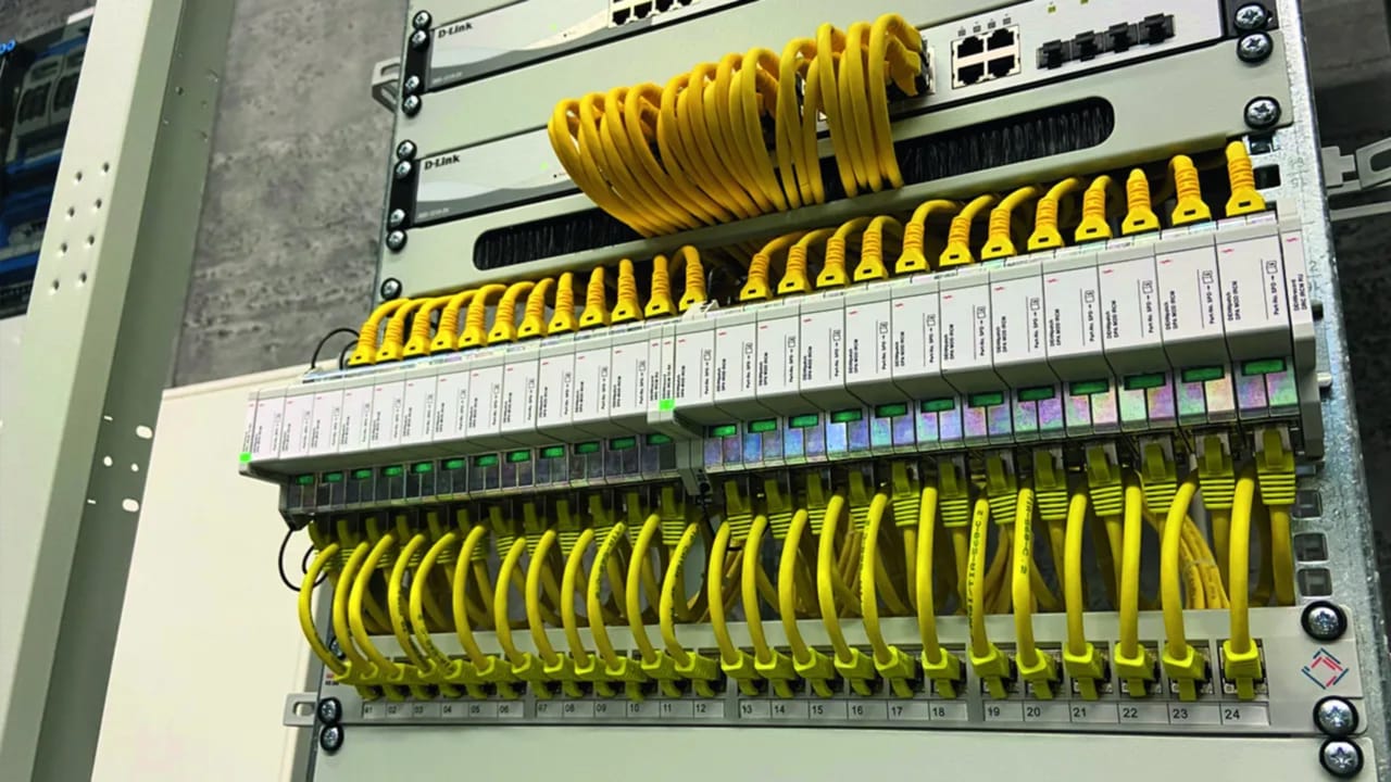
In-depth technical guide to SPDs on data lines, Ethernet/PoE, CCTV, automation, telecommunications and control, integrated with SPM, LPZ, grounding, equipotential bonding, LPS and engineering design.
Check it out!
SPDs for data lines, CCTV, automation and telecommunications are surge protective devices applied to signal, communication and control circuits, where overvoltage can reach equipment through metallic conductors even when the main electrical power supply already has SPDs. Proper protection must limit transient energy without degrading transmission, changing channel impedance, introducing losses incompatible with the protocol or creating an inadequate equipotential-bonding reference.
For this reason, selecting a protector only by its connector — for example, “RJ45 SPD,” “camera SPD” or “RS-485 SPD” — is not sufficient. It is necessary to know the electrical interface, normal circuit voltage, allowable current, bandwidth or data rate, signal modes, shielding, cable route, existence of external lines, grounding system, equipotential bonding, LPS, lightning protection zones and the protection architecture of the equipment power supplies.
ABNT NBR 5410 explicitly addresses protection against overvoltages on both power and signal lines. IEC 61643-21 establishes performance requirements and test methods for SPDs connected to telecommunications and signaling networks, including protection parameters as well as transmission characteristics. ABNT NBR 5419-4:2026, in turn, places these lines within the broader architecture of Surge Protection Measures — SPM: boundaries between zones, metallic conductors entering or leaving the structure, equipotential bonding, routing, shielding and coordination between power and signal protection must be analyzed as a system.
In corporate, industrial and mission-critical installations, therefore, installing SPDs at isolated points is not enough. Protection must originate from a technical survey and engineering design that simultaneously consider the electrical installation, grounding, equipotential bonding, external and internal LPS, metallic interfaces between environments or buildings, equipment power supplies and the withstand of protected electronic ports.
Why are data and signal lines also exposed to surges?
An overvoltage does not need to enter through a 127 V, 220 V or 380 V power supply to damage equipment. Any metallic conductor connected to an electronic system can serve as a path for coupling transient energy. This includes twisted pairs, coaxial cables, serial circuits, field contacts and signals, telephone lines, control cables, antennas and metallic interconnections between buildings.
IEC 61643-21 considers telecommunications and signaling networks exposed to the effects of lightning and power-system faults through direct contact, inductive, capacitive, electromagnetic or conductive coupling. The consequence can be overvoltage, overcurrent or both.
In practice, four mechanisms occur frequently:
- rise of grounding-system potential while lightning current is being conducted;
- electromagnetic induction in loops created by cable routing;
- conducted surges through external lines, cables between buildings, antennas or equipment installed outside the structure;
- potential differences between grounding references interconnected by a metallic communication interface.
Adequate protection requires identifying which of these mechanisms is plausible in each section. The mere presence of an SPD does not eliminate the cause of coupling.
Power SPDs and signal SPDs are not the same device
The general principle is similar: the SPD limits transient voltage and diverts or restricts energy before it reaches a vulnerable port. But the selection criteria differ.
In power circuits, parameters such as Uc, Up, In, Iimp, Imax, ISCCR, TOV and backup protection dominate the specification. On signal lines, besides protection level and surge capability, the device can participate directly in the transmission path. This makes quantities such as rated current, series resistance, capacitance, insertion loss, return loss, longitudinal balance, bit error ratio and near-end crosstalk relevant, depending on the application.
| Aspect | Power SPD | Signal/telecom SPD |
| Main function | limit overvoltage on the power supply | limit overvoltage/overcurrent at a communication or control interface |
| Critical quantities | Uc, Up, In, Iimp, Imax, ISCCR, TOV | Uc, Up, rated current, impulse capability, series resistance and transmission requirements |
| Influence on normal operation | normally small when correctly selected | can directly affect bandwidth, impedance, BER, NEXT and insertion loss |
| Connection reference | PE, neutral, phases, main bonding bar according to arrangement | nearest equipotential reference, shield, chassis or common terminal according to design |
| Typical product standard | NBR IEC 61643-11 | IEC 61643-21 |
This explains why a protector generically described as being “for networks” should not be specified merely by the appearance of its connector.
What IEC 61643-21 requires you to evaluate
IEC 61643-21 treats the SPD as a “black box” whose performance must be declared and tested. The device may contain voltage-limiting elements, current-limiting components or both. Depending on the application, it must also meet transmission requirements.
Relevant information includes maximum continuous operating voltage Uc, rated current, protection level Up, impulse capability, overload failure mode and, where applicable, characteristics such as series resistance. For applications with more demanding communication requirements, the standard provides tests for capacitance, insertion loss, return loss, longitudinal balance, bit error ratio — BER — and near-end crosstalk — NEXT.
The engineering point is simple: the SPD must protect the port while continuing to allow the port to perform its function. A device that limits a surge very effectively but compromises the communication channel is not suitable for that interface.
Uc and Up also matter in signal circuits
The maximum continuous operating voltage Uc is the highest voltage that can remain applied to the SPD terminals without degrading its transmission characteristics. It must therefore be compatible with the voltage actually present at the interface, including bias, remote power and normal operating conditions.
The protection level Up characterizes the SPD’s capability to limit impulse voltage. To be useful, it must be sufficiently low relative to the withstand of the protected port. However, reducing Up indiscriminately may also have consequences such as higher capacitance or behavior incompatible with normal circuit voltage, depending on technology.
Selection must balance at least:
1. normal and maximum interface voltage; 2. impulse withstand of the equipment; 3. waveform and energy of the expected surge; 4. electrical behavior of the SPD during normal traffic; 5. coordination with other protection stages.
This is the same engineering logic seen in selecting Uc for power SPDs, but applied to an interface whose primary function is to carry information.
Transmission characteristics: protection must not degrade the channel
In Ethernet, video, serial data and other communication circuits, the channel is designed for specific electrical and frequency characteristics. Inserting a component into that channel can cause reflection, attenuation, imbalance and crosstalk.
IEC 61643-21 includes tests to assess these effects, particularly capacitance, insertion loss, return loss, longitudinal balance, BER and NEXT where applicable.
Insertion loss
Insertion loss represents the signal reduction caused by introducing the SPD. The higher the operating frequency, the more important it is to know the device’s performance across the used bandwidth.
Return loss
Impedance discontinuities can cause part of the signal to reflect back toward the source. In high-speed data links, this can reduce operating margin and affect channel integrity.
Longitudinal balance
In balanced circuits such as twisted pairs, symmetry relative to earth helps reject common-mode interference. A poorly selected SPD can impair this characteristic.
NEXT and BER
Near-end crosstalk and bit error ratio help verify whether protection introduces degradation incompatible with digital transmission. This makes clear that specifying an SPD for data cannot be separated from the transmission performance of the network itself.
Ethernet and PoE: the SPD must account for data and power
In Ethernet networks with Power over Ethernet, the same metallic link carries both communication and power. This creates an additional problem: the protector must simultaneously be compatible with transmission and the PoE power regime in use.
The specification should verify, among other points:
- link category and speed;
- number of pairs used;
- PoE mode and power;
- continuous current carried by the pairs;
- maximum voltage present;
- cable and connector shielding, where present;
- grounding and equipotential bonding of the infrastructure;
- location of the protector relative to equipment and protection boundary;
- surge-current path to the equipotential reference.
An incompatible SPD can introduce loss, imbalance or current limitation. In higher-power PoE systems, heating and continuous-current carrying capability also need to be checked.
Outdoor IP cameras
A camera installed on a pole, rooftop, façade or perimeter may be connected to the building through a metallic Ethernet cable while being located in an electromagnetic exposure condition very different from that of the switch or server receiving the signal.
In such cases, the design should assess whether the link crosses an LPZ boundary, whether there is risk of potential difference between metallic structures, how it relates to the LPS, where equipotential bonding occurs, and whether conversion to optical fiber is technically more appropriate than maintaining a long metallic interconnection.
A common mistake is to protect only the camera. Depending on the architecture, the switch port at the other end remains exposed.
SPDs in CCTV: IP, coax and power must be analyzed together
Video-surveillance systems can present different surge paths: camera or power-supply electrical power; Ethernet/PoE; coaxial cable in legacy systems or specific applications; alarm contacts, audio, I/O or PTZ control; metallic structures, supports and masts; interconnections between buildings or outdoor areas.
In IP CCTV, it is common for the same device to receive PoE power and have a metallic enclosure installed outdoors. In coaxial systems, the signal path has a different impedance and connector type, requiring a specific protector.
Protection should not be designed merely by “camera type.” What matters are all conductive interfaces that cross the boundary between electromagnetically different environments.
Automation, PLCs, instrumentation and serial networks
Industrial automation lines can connect sensors, actuators, PLCs, remote I/O, variable-frequency drives, instruments and supervisory systems distributed across large areas. Many of these interfaces operate at low voltages and are highly sensitive to surges.
RS-485, RS-422, industrial buses and analog signals require attention to topology, common mode, biasing, electrical reference and shielding. Installing an unsuitable SPD can change impedance, increase capacitance or introduce an earth reference that was not part of the original design.
In instrumentation, the issue becomes even more critical when low-amplitude signals share routes with power circuits or cross outdoor areas.
The complete loop must be analyzed: source, destination, shielding, shield grounding, equipotential bonding, routing, proximity to power conductors and the most appropriate point at which to limit transient energy.
Access control, alarms and electronic security systems
Access-control panels, readers, sensors, actuators, doors, gates and peripherals may use Ethernet, RS-485, dry contacts or other low-voltage signals. The risk is similar to automation: cables may leave the rack’s equipotential area and reach façades, entrances, guardhouses, gates or other structures.
In these cases, protection must simultaneously consider power to controllers and peripherals, communication interfaces, outdoor cables, associated metallic structures, distances and routing, and earth references at each end.
SPD design should be integrated into the system design rather than added at the end as an accessory.
Telecommunications, telephony and external lines
ABNT NBR 5410 establishes specific location criteria for SPDs on signal lines. Lines originating from the public telephone network should be protected at the main distribution point located beside the main equipotential bonding bar; other external public lines should be protected beside the main bonding point; and lines continuing to another building, annex, antenna or rooftop structure should be treated at the nearest equipotential reference.
The standard also requires signal SPDs to be connected to the nearest equipotential reference. Depending on the installation point, this reference may be the main bonding bar, local bonding bar, PE bar, distributor earth bar or a terminal bonded to equipment chassis.
This demonstrates why grounding and equipotential bonding are not accessories to the SPD. They are part of the physical path through which transient current will be conducted.
Main/local bonding bars and equipotential bonding: where will surge energy flow?
Installing an SPD means deliberately creating a low-impedance path for transient energy. The design question is therefore not merely “which SPD should be used?” but where will this current be conducted and what potential difference will occur during the event?
Equipotential bonding integrates exposed conductive parts, conductive elements and grounding systems so as to control potential differences. In signal-line protection, the reference selected for the SPD must make sense within this architecture.
If “independent” grounds are indirectly interconnected by a data cable, the link itself may become a path for potential equalization during a surge. This condition must be investigated before adding protective devices.
The grounding system will be decisive in understanding references, protective conductors, bonding bars, shields and current paths.
Lightning Protection Zones — LPZ — and protection boundaries
ABNT NBR 5419-4:2026 structures SPM around lightning protection zones. The logic is to progressively reduce the electromagnetic environment and limit conducted surges at boundaries between zones.
This is particularly useful for data systems. A cable leaving a protected technical room and reaching an outdoor camera, antenna, guardhouse or another building may cross different LPZ. The design should identify these boundaries and decide where to apply equipotential bonding, SPDs, shielding, routing or isolating interfaces.
For existing structures, Annex B of NBR 5419-4:2026 recommends a survey identifying power and signal lines, supply type, cable routing, shielding, equipment location, metallic interconnections between structures, interface types and TN, TT or IT earthing arrangements. These data are the basis of the SPM design, not a detail to be addressed after purchasing SPDs.
When an existing installation is undocumented, the initial stage may require an Inspection, Diagnosis and Retrofit of SPDs and SPM before executive design is defined.
Do power and signal lines cross LPZ boundaries or connect outdoor areas?
In this scenario, protection needs to be defined as an SPM architecture — coordinating SPDs, grounding, equipotential bonding, routing, shielding and isolating interfaces. The Surge Protection Measures (SPM) Design consolidates these criteria into a verifiable solution.
Power and signal must be protected as a single system
A recurrent mistake is to install SPDs on the electrical network and consider the equipment protected even when it has metallic communication lines leaving the protected zone.
Consider an IP camera powered by a local supply. The power SPD may limit the surge arriving through the electrical network. But if the metallic Ethernet cable runs outdoors for tens of meters, another overvoltage can appear between the network port and the device’s chassis reference.
The reverse is also true: a well-selected data SPD does not compensate for a power supply without coordinated protection.
NBR 5419-4:2026 works with coordinated protection of all electrical lines crossing relevant boundaries, including power and signal. This is why SPD coordination should not be understood only as “Class I + Class II + Class III” in electrical switchboards.
When is optical fiber a better protective measure than an SPD?
Optical fiber does not conduct electrical current through the transmission medium. In links between buildings, outdoor areas or different earth references, converting a metallic link to fiber can eliminate a significant conductive path.
This does not mean every fiber system solves every problem. Optical cables may contain metallic strength members or armor; media converters still require power; and the system as a whole still needs coherent grounding, equipotential bonding and power protection.
The decision between keeping copper protected by SPDs and migrating a section to fiber depends on distance, bandwidth, criticality, exposure, topology, life-cycle cost and telecommunications architecture.
Connection length and inductance also matter for signal protection
NBR 5410 requires SPD connections to be as short and straight as possible. This concern results from the impedance associated with connections during pulses having high rates of current change.
On signal lines, the protector should be physically close to the boundary or equipment it needs to protect and connected to the appropriate equipotential reference through a short path. Long conductors between the SPD and bonding bar can increase the effective voltage seen by equipment during a surge.
The protector position should be defined in the layout and installation design rather than chosen merely according to available space in a rack or switchboard.
An external LPS does not replace SPDs — and SPDs do not replace the LPS
The external LPS performs the functions of intercepting, conducting and dispersing lightning current. SPM address electromagnetic effects and surges that can reach internal systems. The two disciplines are related but are not interchangeable.
An installation associated with LPS and NBR 5419 can remain vulnerable on its power and signal lines if equipotential bonding, LPZ and SPDs are not properly designed. Likewise, adding SPDs to racks and cameras does not compensate for an inadequate external LPS or grounding system when these are required.
Protection must be conceived as an engineering architecture.
How to design protection for an existing installation
In retrofit work, the first step should not be to draw up a list of SPDs. NBR 5419-4:2026 dedicates a specific annex to implementing SPM in existing structures and recommends surveying construction characteristics, LPS, grounding, power and signal entrances, antennas, routing, shielding, equipment locations, interconnections between structures and interface withstand.
A coherent engineering sequence is:
1. document review — single-line diagrams, as-built documentation, electrical design, telecommunications design, LPS, grounding and system topology; 2. field survey — cable origins and destinations, switchboards, racks, external interfaces, main/local bonding bars, shields and earth references; 3. classification of surge paths and LPZ; 4. assessment of grounding and equipotential bonding; 5. definition of the SPM architecture — SPDs, shielding, routing, isolating interfaces and other measures; 6. selection of devices by electrical and transmission performance; 7. detailed design, including points, connections and specifications; 8. installation, inspection and commissioning; 9. documentation update and periodic maintenance.
This process is the object of a Surge Protection Measures — SPM Design. It prevents protection from being reduced to purchasing components selected in isolation.
Does the existing installation lack reliable as-built documentation, identified bonding bars or documented cable routes?
Before specifying new SPDs, actual field conditions need to be characterized. The Inspection, Diagnosis and Retrofit of SPDs and SPM structures the survey, identifies nonconformities and provides a technical basis for retrofit.
Specification criteria by interface type
| Interface | Minimum checks | Risk of inadequate specification |
| Ethernet | category/speed, PoE, shielding, impedance, bandwidth, current | link loss, BER, reduced channel margin |
| Coaxial CCTV | impedance, connector, video bandwidth, reference | reflection, loss and insufficient protection |
| RS-485/RS-422 | voltage, common mode, balancing, topology, baud rate | imbalance, excessive capacitance and communication failures |
| analog signals | amplitude, impedance, accuracy, grounding | measurement error and signal degradation |
| contacts/control | voltage, current, operating frequency | failure to operate or inadequate protection |
| telephony | normal voltage, ringing, current, balance | unwanted operation or reduced quality |
| PoE | voltage, current per pair, power and transmission | heating, voltage drop and data loss |
The table does not replace manufacturer documentation or engineering design. It shows why there is no “universal data SPD.”
Common errors in data-line protection
Errors found in designs and installations include:
- installing SPDs only on the power supply and ignoring metallic signal lines;
- protecting only one end of an exposed interconnection without evaluating the complete path;
- selecting a protector only by its physical connector;
- ignoring bandwidth, insertion loss, return loss, balance or PoE;
- connecting the SPD to an unsuitable or distant earth reference;
- creating a new path for potential difference between supposedly independent grounds;
- failing to consider the LPS, LPZ and equipotential bonding;
- keeping copper between buildings when an isolating interface or fiber would be more appropriate;
- installing the protector far from the protection boundary;
- not protecting auxiliary interfaces on the same equipment;
- not recording the SPD and its specification in the design or as-built documentation;
- repeatedly replacing damaged SPDs without investigating the cause.
Inspection and commissioning
After installation, acceptance should verify more than the physical presence of devices. Depending on the application, it is advisable to compare installed models and parameters against the design, check continuity and quality of equipotential-bonding connections, connection length and routing, shield connections, origin/destination identification, link performance after installation, PoE operation, protector condition and updates to diagrams, cable schedules and as-built documentation.
In structured cabling and Ethernet, channel testing after intervention may be necessary to confirm that the protector has not compromised expected performance.
Has the protection been installed and does it need technical acceptance?
Acceptance should compare SPD models and parameters, equipotential-bonding connections, link performance, identification and final documentation against the design. Electrical Installation Commissioning and Technical Acceptance closes this stage with verifiable criteria.
Installing SPDs is not enough: the solution is a protection architecture
The SPD is only one component of a surge-protection strategy. In real installations, its performance depends on where it is placed, the current and voltage it must withstand, the equipotential reference, grounding, LPS, routing, shielding, coordination with other protective devices and the withstand of the equipment itself.
The technically correct approach is therefore not “put an SPD on every cable.” It is to identify propagation paths, establish protection boundaries and specify the measures required for each interface.
When existing conditions are unknown, the solution begins with survey and diagnosis. Once the architecture is characterized, it advances to SPM design and coordination with electrical, grounding, LPS and special-systems designs. Installation follows the design — and should be commissioned against it.
Technical references
[1] ABNT. ABNT NBR 5410:2004 — Low-voltage electrical installations.
Frequently asked questions
No. Power and signal are different surge-propagation paths. Protection must be coordinated among power supplies, metallic interfaces, grounding, equipotential bonding and the other SPM.
No. The specification must consider link speed, PoE, voltage and current, shielding, protection level and transmission characteristics such as insertion loss, return loss, balance and crosstalk where applicable.
Location and quantity depend on the LPZ architecture, equipotential references, route and exposure. Metallic interconnections between structures must be analyzed as a whole; in some cases, optical fiber or an isolating interface may be technically preferable.
No. The external LPS does not replace protection of power and signal lines. SPM, equipotential bonding, grounding, routing, shielding and coordinated SPDs address the effects on internal systems.
In distributed, outdoor, industrial or critical installations, the specification depends on data that require engineering survey and analysis. Installing protectors in isolation does not guarantee coordination or adequate protection.
Complementary technical materials
Related solutions
Related engineering services
- Surge Protection Measures (SPM) Design
- Inspection, Diagnosis and Retrofit of SPDs and SPM
- Grounding Design
- Low-Voltage Electrical Design
Related technical content
- SPD: What It Is, What It Does, Classes, Sizing and Installation
- SPD Coordination: Cascading, Energy, Up/f and Equipment Protection
- NBR 5419-4: Internal LPS, SPDs and System Protection
- Equipotential Bonding
- Electrical Grounding: Function, Types, NBR 5410, SPDs and LPS
