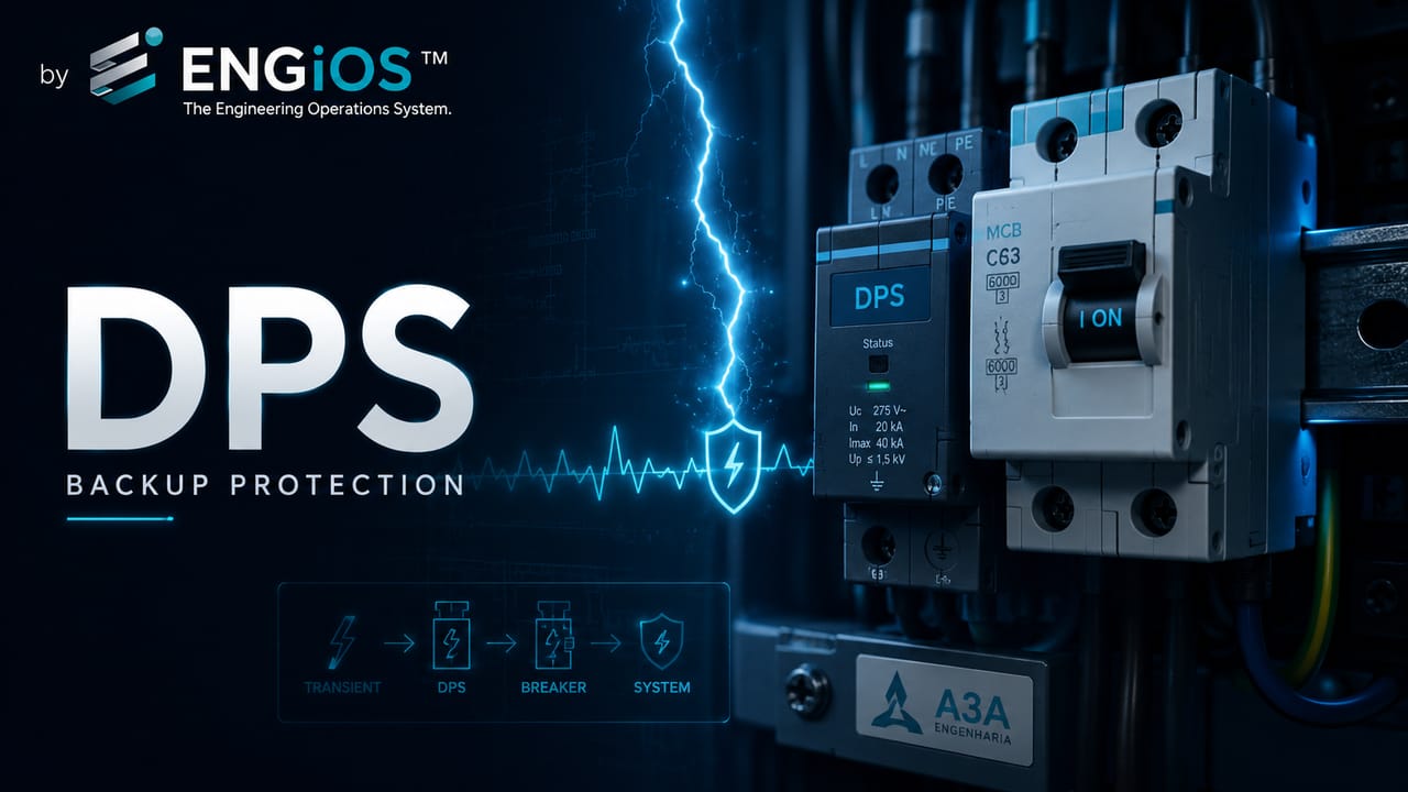
Understand the relationship between SPDs and circuit breakers: backup protection, short-circuit current, ISCCR, fuses, rated current, interrupting capacity, selectivity and NBR 5410 criteria.
Check it out!
The expression “SPD circuit breaker” appears frequently because the two devices are usually installed in the same switchboard and, in many cases, work in coordination. Technically, however, an SPD and a circuit breaker are not the same thing. An SPD — Surge Protective Device — limits transient overvoltages and diverts surge currents; a circuit breaker is an overcurrent protective device intended primarily to interrupt overloads and short circuits within its rated characteristics.
The relationship between them exists because an SPD can degrade or fail internally and develop into a short-circuit condition. In that situation, there must be a means of disconnection capable of safely clearing the fault current. This means may be incorporated into the SPD itself, may be an external device installed specifically in its branch connection, or, in certain arrangements, may be the overcurrent protection of the circuit to which the SPD is connected.
Therefore, there is no universal rule such as “every SPD must use an X-amp circuit breaker”. Selection depends on the prospective short-circuit current at the point, the maximum rated current of the protective device specified by the SPD manufacturer, the connection arrangement, conductors, selectivity, and the service-continuity strategy. Values such as 20 kA or 40 kA marked on the SPD also do not correspond to the circuit breaker’s rated current and cannot be used directly to select backup protection.
Understanding this distinction avoids two common mistakes: installing an SPD without adequate protection against its own failure or, at the other extreme, selecting a circuit breaker according to a generic rule that does not correspond to the tests, the available short-circuit current, or the manufacturer’s instructions.
Getting the backup protection right and installing the SPD is not enough either. The assembly must be part of the installation design: short-circuit current, switchboard ratings, TN, TT or IT earthing arrangement, RCD, PE, grounding, equipotential bonding, LPS/SPM, connection length and coordination with other SPDs all affect performance. In existing installations, inadequacies in these systems may require diagnosis and an electrical retrofit design before components are simply replaced or added.
Are an SPD and a circuit breaker the same thing?
No. Although both take part in protecting the electrical installation, they act on different phenomena and have different rated quantities.
| Device | Main function | Phenomenon addressed | Typical specification quantities |
| SPD | Limit overvoltage and divert surge current | Lightning, induced surges and switching transients | Uc, Up, In, Iimp, Imax, ISCCR, TOV |
| Circuit breaker | Interrupt overcurrents | Overload and short circuit | In, trip curve or trip unit, Icn/Icu/Ics, rated voltage |
An SPD normally remains connected to the installation waiting for a transient event. When the voltage across its terminals rises beyond the expected conditions, its nonlinear components change behavior and begin to conduct part of the surge current. The device then returns to a high-impedance state, provided the event is within its capability and no irreversible degradation has occurred.
The circuit breaker, in turn, monitors circuit current. Depending on its technology and tripping characteristic, it opens the circuit when it detects an overload or short-circuit current exceeding its operating thresholds.
This distinction matters because a surge current of tens of kiloamperes lasting microseconds must not be confused with a power-frequency short-circuit current that has to be interrupted by the overcurrent protective device.
The main guide to SPDs details operation, classes, Uc, Up, In, Iimp and the other device parameters. Here, the focus is exclusively on the interface with circuit breakers, fuses and backup protection.
Why can an SPD require overcurrent protection?
The protection is required because of a possible SPD failure mode. A device subjected to progressive degradation, unsuitable temporary overvoltage, thermal stress or an event beyond its capability can lose its normal characteristics and create a permanent low-impedance path.
ABNT NBR 5410 explicitly addresses the possibility of an SPD failing internally as a short circuit. In that condition, an overcurrent protective device capable of clearing the short circuit must be provided. The standard distinguishes alternative positions for that device and shows that the choice directly affects continuity of service and continuity of surge protection itself.
ABNT NBR IEC 61643-11:2021 complements this logic from the product side. It requires the SPD to have internal disconnectors, external disconnectors, or both — subject to specific exceptions — and requires safe behavior under short-circuit current. The manufacturer must state the conditions under which the device was tested and the characteristics of the associated disconnectors.
This means the circuit breaker or fuse associated with the SPD is not a component selected merely for installation convenience. It forms part of the safety condition of the assembly.
An internal disconnector does not necessarily mean complete circuit protection
Many SPDs include internal thermal disconnection mechanisms or other safety devices. They can take a degraded component out of service and operate the module’s status indicator.
However, the existence of that disconnector does not automatically eliminate the need to verify the prospective short-circuit current and the manufacturer’s instructions. ABNT NBR IEC 61643-11 tests the SPD considering its architecture, its disconnectors and, where applicable, the specified external protection.
It is therefore incorrect to conclude that an SPD “with an internal fuse” or “with a thermal disconnector” can be installed anywhere in the network regardless of the available current.
Does an SPD always require a dedicated circuit breaker?
Not necessarily. NBR 5410 allows different ways of providing overcurrent protection associated with SPD failure.
One possibility is to install a dedicated protective device in the SPD branch itself. This arrangement isolates only the branch where the SPD is connected when a failure occurs, preserving power to the remainder of the installation. The disadvantage is that the installation can remain energized without protection against subsequent surges until the SPD is replaced.
Another possibility is to use the protection of the circuit to which the SPD is connected. In this case, an SPD failure can operate the general protection of that circuit and interrupt its supply. Availability is lower, but the installation does not continue operating indefinitely with a failed SPD connected.
Higher-availability architectures can also use redundancy and individually protected branches. NBR 5410 presents this reasoning when discussing alternatives that prioritize continuity of service, continuity of protection, or both.
The choice depends on system criticality. In a small distribution board, one solution may be sufficient; in data centers, industrial processes, control centers, telecommunications or mission-critical installations, downtime caused by an SPD failure has to be treated as an engineering requirement.
What is SPD backup protection?
Backup protection is the overcurrent protective device used to clear a short-circuit current resulting from an SPD failure when this function is not fully provided by the SPD’s own architecture.
In practice, the term may refer to an external fuse or circuit breaker installed in series with the SPD branch. It does not act on the surge in the same way as the SPD; its function is to interrupt the power-frequency current that may continue to flow after the surge device has failed.
This time-domain distinction is decisive. The transient current characterized by In, Imax or Iimp has a waveform and duration completely different from the short-circuit current the circuit breaker or fuse must interrupt.
The specification therefore has to verify two layers of protection:
1. SPD performance against the expected surges, through Uc, Up, In, Iimp and other parameters; 2. safe behavior in the event of SPD failure, considering prospective short-circuit current, ISCCR, disconnectors and the overcurrent protective device.
How should the SPD protective circuit breaker be sized?
The process does not start with the SPD’s In or Imax value. The correct sequence begins with the electrical conditions at the installation point and the product documentation.
1. Determine the prospective short-circuit current at the point
The first input is the current that could flow if a short circuit occurred where the SPD is installed. This value depends on the source, transformer, conductor impedances, network topology and distance to the fault point.
In industrial installations, main low-voltage switchboards and boards close to transformers, this current can be much higher than in final circuits. The selected protection must have an interrupting capacity compatible with that condition.
When the value is not known, the short-circuit and protection-coordination study provides the prospective current at busbars and other relevant points in the installation.
Will the SPD be installed in a main switchboard, close to transformers or on a busbar whose short-circuit current is not documented?
The Short-Circuit, Selectivity and Protection Coordination Study determines prospective currents and enables verification of ISCCR, interrupting capacity, backup device and selectivity before the specification is finalized.
2. Verify the short-circuit rating of the SPD + protection assembly
ABNT NBR IEC 61643-11 uses the SPD’s rated short-circuit current together with the specified disconnectors. In practice, the datasheet should state the test condition or the maximum/required protection for the assembly to achieve a given withstand rating.
Checking only the circuit breaker’s interrupting capacity is not enough. It is necessary to confirm that the SPD was tested to operate with that protective device or within the conditions declared by the manufacturer.
3. Respect the maximum protection specified by the manufacturer
NBR 5410 requires the device intended to clear a short circuit resulting from SPD failure to have a rated current lower than or, at most, equal to that specified by the SPD manufacturer.
This eliminates a dangerous practice: selecting a circuit breaker with an excessively high rated current merely to avoid trips. If its rated current exceeds the limit considered in SPD coordination, the let-through energy during a fault may exceed the assembly’s capability.
4. Verify the circuit breaker or fuse interrupting capacity
In addition to the rated current in amperes, the protective device must be able to withstand and interrupt the prospective short-circuit current at the point.
For circuit breakers, quantities such as Icn, Icu and Ics apply according to device type and the relevant standard. The article on circuit-breaker interrupting capacity discusses these distinctions in greater depth.
5. Verify the SPD branch conductors
Short-circuit current also stresses the conductors between the busbar, backup protection and SPD. Cross-sectional area and length must be compatible with the maximum possible current and the protective-device operating time.
At the same time, SPD conductors should be kept as short and straight as possible so that residual voltage during a surge is not increased. The design must therefore satisfy both thermal withstand requirements under short circuit and low inductance for surge-protection performance.
ABNT NBR 5419-4:2026 reinforces this interface by including the voltage drop in the connections and in the branch short-circuit protection when assessing the effective protection level Up/f. Annex C notes that using a fuse as branch short-circuit protection may be preferable for reducing this voltage-drop contribution. This does not make a fuse universally superior to a circuit breaker: selection still depends on the condition tested by the manufacturer, prospective current, selectivity and the installation’s maintenance philosophy.
6. Verify selectivity and continuity of service
The device dedicated to the SPD must not be analyzed in isolation. Its operation has to be coordinated with the main circuit breaker and the other protective devices in the installation.
In the event of SPD failure, it should be known in advance which device is expected to open and which part of the installation will be de-energized. This analysis is especially relevant when operational continuity is a project requirement.
20 kA or 40 kA SPD: which circuit breaker should be used?
There is no direct conversion between the SPD’s kiloampere values and the circuit breaker’s rated current.
An SPD marked 20 kA, 40 kA or 45 kA may be stating In or Imax, depending on the product. A Class I SPD may also highlight Iimp. These values characterize performance against surge currents and do not correspond to the ampere rating of the backup circuit breaker.
Compare the quantities:
| Example marking | Unit | What it represents | Can it directly determine the circuit breaker? |
| In = 20 kA | kA, 8/20 µs waveform | SPD nominal discharge current | No |
| Imax = 40 kA | kA, 8/20 µs waveform | Declared maximum discharge current | No |
| Iimp = 12.5 kA | kA, Class I test | Impulse current | No |
| 32 A circuit breaker | A | Protective-device rated current | — |
| Icu = 25 kA | kA | Circuit breaker’s ultimate short-circuit breaking capacity | Must be compared with prospective short-circuit current, not SPD In |
A 40 kA SPD can therefore use backup protection with different rated currents depending on the manufacturer, product family and available short-circuit current. The datasheet and system coordination are decisive.
Circuit-breaker rated current and interrupting capacity are different things
Another common error is to look only at the circuit breaker’s rated current. A 32 A, 50 A or 63 A device defines its operating condition and response to overcurrent, but that alone does not state which short-circuit current it can safely interrupt.
Two 32 A circuit breakers can have very different interrupting capacities. In a switchboard with high prospective short-circuit current, the rated current can be correct while the interrupting capacity is insufficient.
Sizing SPD backup protection therefore involves at least three independent checks:
- the maximum rated current allowed by the SPD manufacturer;
- the protective device’s interrupting capacity against the prospective short-circuit current;
- selectivity with upstream and downstream protective devices.
The low-voltage circuit-breaker sizing method details breaker selection from the electrical-circuit perspective.
Should the SPD circuit breaker be before or after the SPD?
For a one-port SPD connected as a branch, the backup protective device is in series with the branch feeding the SPD. This means current destined for the SPD passes through the dedicated circuit breaker or fuse before reaching the surge protective device.
The expression “before or after” can be misleading because an SPD does not operate like a conventional load connected in series with the main feeder. In common applications, it is connected between active conductors and the protective reference — for example, phase-PE, phase-neutral or neutral-PE, according to the intended arrangement.
The design has to define:
- where the SPD branch point is;
- which device protects that branch;
- the surge-current path;
- the equipotential-bonding reference;
- how total connection length will be minimized.
An electrically correct arrangement with long conductors between busbar, backup protection and SPD can significantly increase the effective voltage applied to equipment during a surge.
Dedicated circuit breaker or fuse: which is better for an SPD?
There is no universal answer. Both circuit breakers and fuses can be used when specified by the manufacturer and compatible with the installation.
A fuse has high interrupting capacity and well-characterized energy behavior and is often used in applications with high short-circuit currents. Its operation, however, requires replacement.
A circuit breaker can be reset and may simplify maintenance and isolation of the SPD branch. Its selection must nevertheless consider tripping characteristics, interrupting capacity, coordination with upstream protection and compatibility with the SPD.
The decision should start from the manufacturer’s technical documentation and the installation’s protection philosophy, not from a generic preference for one device type.
What happens when the backup protection operates?
When a circuit breaker or fuse dedicated to the SPD opens because of an internal failure, the rest of the switchboard may remain energized. This continuity is advantageous operationally, but it creates a new risk condition: the installation can continue operating without that stage of surge protection.
The SPD therefore needs status indication, and the design should allow loss of protection to be identified and addressed. In critical systems, remote signaling contacts can be integrated with supervision or automation systems.
If the circuit’s general protection is instead used to clear SPD failure, the consequence may be disconnection of the entire feeder. Surge protection is no longer the only system affected; continuity of service is interrupted as well.
The choice between these philosophies should be consistent with project criticality and its risk matrix.
How does selectivity affect SPD protection?
If there is a circuit breaker dedicated to the SPD and another device upstream, both are electrically in series for the branch fault current. Selectivity seeks to ensure that the protective device closest to the fault operates first, preserving the rest of the installation.
Without proper coordination, failure of a single SPD may trip the main circuit breaker even when dedicated branch protection exists. In installations with continuity requirements, this behavior can turn a localized failure into a broad outage.
The analysis involves time-current curves, let-through energy, device characteristics and prospective short-circuit current. The content on circuit-breaker selectivity and the article on SPD coordination address the two sides of this interface.
What is the relationship among SPDs, circuit breakers and RCDs?
SPDs, circuit breakers and residual current devices act on different phenomena:
- the SPD limits transient overvoltages;
- the circuit breaker protects against overcurrent;
- the RCD responds to residual current for electric-shock protection and other applications defined by design.
NBR 5410 permits SPDs upstream or downstream of RCDs under specific conditions. When the SPD is downstream, RCD immunity to surge currents must be considered; in certain TT arrangements, connecting the SPD upstream also requires specific precautions.
The physical sequence in the switchboard should therefore not be defined by simplified phrases such as “SPD first, then RCD, then circuit breaker.” The arrangement depends on the TN, TT or IT earthing system, switchboard architecture and the function of each device.
Does the switchboard need an SPD, RCD and new backup protection, but the existing architecture is incompatible or undocumented?
The Low-Voltage Electrical Design coordinates TN/TT/IT arrangements, circuit breakers, RCDs, busbars, conductors, short-circuit levels, grounding, equipotential bonding and SPDs into an executable and documented solution.
The article on RCD device types discusses this protection in detail.
What is ISCCR and why does it matter?
ABNT NBR IEC 61643-11 establishes tests for SPD behavior under short-circuit currents and considers the rated short-circuit current of the assembly under the conditions declared by the manufacturer.
In technical literature and product datasheets, this characteristic may be associated with the acronym ISCCR — short-circuit current rating. The concept represents the capability of the SPD, considered together with the specified disconnectors, to remain safe when subjected to the corresponding prospective current.
This parameter must not be confused with In or Imax. An SPD can withstand high surge currents and still require a specific protective device to achieve a given short-circuit rating.
In main switchboards and boards close to the source, this verification is particularly important because available fault current can reach tens of kiloamperes.
Examples of decisions in different installations
The following examples are conceptual. They do not replace calculation or manufacturer documentation.
Distribution board with low short-circuit current
In a board located far from the transformer, feeder impedance can significantly reduce prospective current. A Class II SPD may be installed with dedicated protection according to the maximum current specified by the manufacturer, provided that the circuit breaker’s interrupting capacity remains above the calculated fault current.
The fact that the SPD is “40 kA” does not determine whether the circuit breaker should be 20 A, 32 A, 50 A or another rating.
Main low-voltage switchboard close to a transformer
In a main switchboard with high short-circuit current, the same SPD model may require specific external protection or may be unsuitable for the available condition. Verification of ISCCR and backup-device interrupting capacity becomes critical.
In this situation, replacing a fuse specified by the manufacturer with a circuit breaker of the same rated current, without checking tests and coordination, can completely change assembly performance.
Mission-critical installation
When continuity is a project requirement, dedicated SPD branch protection may be preferable to avoid disconnecting the entire switchboard. The tradeoff is the need to supervise SPD condition and respond quickly if protection is lost.
The design may also provide redundancy or a multistage architecture depending on risk and criticality.
How should the backup protection of an existing SPD be inspected?
A technical inspection should not merely verify whether there is a circuit breaker next to the SPD. It must confirm that the assembly remains compatible with the current installation.
The verification should include:
- identification of the SPD model and characteristics;
- rated current and interrupting capacity of the associated circuit breaker or fuse;
- current manufacturer instructions for maximum protection and coordination;
- prospective short-circuit current at the point;
- SPD status and indication;
- tightness and integrity of connections;
- conductor cross section and length;
- selectivity with upstream devices;
- later changes to transformer, feeders or main switchboard;
- compatibility with the earthing arrangement and RCDs.
A change apparently remote from the SPD can invalidate its protection. Replacing a transformer with a higher-capacity unit, reducing source impedance or replacing the main circuit breaker may increase the prospective short-circuit current and require a new verification.
When documentation does not represent actual conditions, an electrical-installation inspection can precede diagnosis and the retrofit design.
Are there existing SPDs, unknown backup protection, a history of operation, or changes to transformers and switchboards?
The Inspection, Diagnosis and Retrofit of SPDs and SPM checks SPDs, disconnectors, prospective current, grounding, equipotential bonding, coordination and documentation in the field to define what must be corrected before protection is replaced or expanded.
Common mistakes when combining an SPD and a circuit breaker
The most common errors result from comparing quantities that do not represent the same phenomenon or from applying universal rules to different products.
1. Selecting the circuit breaker from the kA value printed on the SPD. In, Imax and Iimp are not the circuit breaker’s rated current. 2. Ignoring the maximum protection specified by the manufacturer. An oversized circuit breaker may fail to protect the assembly under the test condition considered. 3. Checking rated current and forgetting interrupting capacity. A 32 A circuit breaker may be unsuitable for a busbar whose short-circuit current exceeds its capability. 4. Considering only the circuit breaker and ignoring the SPD’s ISCCR. Safety depends on the assembly. 5. Replacing a fuse with a circuit breaker based only on equal ampere ratings. Let-through energy and coordination may differ. 6. Installing dedicated protection without assessing selectivity. A localized failure may still trip the main protection. 7. Lengthening connections to accommodate the circuit breaker. Short-circuit protection improves, but surge protection may worsen because of added inductance. 8. Failing to provide indication of a disconnected SPD. The installation continues to operate apparently normally but without surge protection. 9. Changing the installation without recalculating short-circuit current. Previously adequate protection may become insufficient. 10. Applying a generic diagram without checking TN, TT or IT. Connections and temporary overvoltages depend on the earthing arrangement.
When should the issue be treated as an engineering design problem?
In new installations, surge protection should be part of the electrical design from the definition of switchboard architecture. The design needs to document SPDs, connection modes, backup protection, the short-circuit current considered, conductors, coordination and inspection requirements.
In existing installations, simply replacing the SPD with a “stronger” model may not solve the problem. When there are recurring failures, missing documentation, extensions, transformer replacement, LPS changes or switchboard modifications, diagnosis should consider the complete system.
The Low-Voltage Electrical Design consolidates diagrams, specifications and protection criteria. When fault current is relevant to selection, the Short-Circuit, Selectivity and Protection Coordination Study provides the quantitative basis for verifying circuit breakers, fuses, panels and SPD backup protection.
Final acceptance should confirm that installed devices correspond to the design and the datasheets used for coordination. In industrial or critical systems, electrical-installation commissioning can verify identification, configuration, documentation and operating conditions before handover.
The correct question is therefore not “which circuit breaker should I use for a 40 kA SPD?”. The engineering question is: which overcurrent protective device keeps the SPD safe under the available short-circuit current, while respecting the manufacturer’s tested condition and the installation’s continuity philosophy?
Technical references
[1] ASSOCIAÇÃO BRASILEIRA DE NORMAS TÉCNICAS. ABNT NBR 5410:2004 — Low-voltage electrical installations. Corrected version 2008. Consult the current edition in the ABNT Catalog.
[2] ASSOCIAÇÃO BRASILEIRA DE NORMAS TÉCNICAS. ABNT NBR IEC 61643-11:2021 — Low-voltage surge protective devices — Part 11: requirements and test methods. Corrected version 2022. Consult the current edition in the ABNT Catalog.
[3] ASSOCIAÇÃO BRASILEIRA DE NORMAS TÉCNICAS. ABNT NBR 5419-4:2026 — Protection against lightning — Part 4: Electrical and electronic systems within structures. Consult the current edition in the ABNT Catalog.
[4] INTERNATIONAL ELECTROTECHNICAL COMMISSION. IEC 61643-11 — Low-voltage surge protective devices — Requirements and test methods for SPDs connected to low-voltage power systems. Consult the official catalog at the IEC Webstore.
Frequently asked questions
An SPD requires an appropriate means of disconnection and protection against the short-circuit current that can arise in the event of failure. This means may be internal, external or a combination, depending on the product and installation. Where an external circuit breaker or fuse is used, selection must follow manufacturer documentation and the prospective short-circuit current.
No. An SPD limits transient overvoltages and diverts surge currents. A circuit breaker primarily protects against overloads and short circuits. They may work in coordination, but their functions and specification quantities are different.
There is no direct conversion between an SPD’s kA value and the circuit breaker’s rated current. The 20 kA or 40 kA may represent SPD In or Imax. The circuit breaker must respect the maximum current specified by the SPD manufacturer, have an interrupting capacity suitable for the prospective short-circuit current and be coordinated with the other protective devices.
For a one-port SPD connected as a branch, backup protection is in series with the branch feeding the SPD. The relevant point is to design the branch, surge-current path and connection length; the SPD is normally not installed in series with the main feeder.
In certain arrangements, the circuit’s own protection may clear the current resulting from SPD failure. The consequence may be disconnection of the entire circuit. NBR 5410 also permits dedicated protection for the SPD branch, which tends to preserve supply continuity provided the assembly is correctly coordinated.
Both may be applicable when specified by the manufacturer. Fuses offer high interrupting capacity and known energy behavior; circuit breakers can be reset and may simplify isolation. Selection must consider SPD documentation, short-circuit current, selectivity and maintenance philosophy.
It is overcurrent protection intended to interrupt the power-frequency current that can flow when an SPD fails as a short circuit. It may be provided by an external fuse or circuit breaker according to the product architecture and manufacturer instructions.
ISCCR is the rating related to the short-circuit current withstand capability of the SPD and specified disconnectors as an assembly. It must be compatible with the prospective short-circuit current at the installation point and must not be confused with In, Imax or Iimp.
No. The circuit breaker’s rated current is expressed in amperes and defines its operating condition. SPD values in kA normally represent surge currents such as In, Imax or Iimp. Icu, Ics or Icn values in kA for a circuit breaker represent short-circuit interrupting capacity.
The SPD branch may be disconnected while the rest of the installation remains energized. This preserves service continuity but may leave the installation without that surge-protection stage. Status indication and prompt maintenance are therefore important.
Complementary technical materials
Related solutions
Related engineering services
- Surge Protection Measures (SPM) Design
- Inspection, Diagnosis and Retrofit of SPDs and SPM
- Short-Circuit, Selectivity and Protection Coordination Study
- Low-Voltage Electrical Design
- Grounding Design
- Electrical Installation Inspection
- Electrical Installation Commissioning and Acceptance
Related technical content
- SPD: What It Is, Classes, Sizing and Installation
- SPD Coordination
- Circuit-Breaker Interrupting Capacity
- How to Size Low-Voltage Circuit Breakers
- Circuit-Breaker Selectivity
