
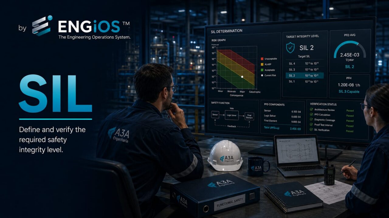
Understand SIL, PFDavg, RRF, SIF, determination and verification, proof testing, architecture, SRS, validation, and governance under IEC 61511.
Check it out!
Safety Integrity Level (SIL) is a discrete measure of the integrity level required or achieved by a safety instrumented function, used to relate the necessary risk reduction to the performance that function must demonstrate throughout its lifecycle. In process applications, SIL must be understood in the context of Functional Safety and IEC 61511: first the risk is identified and the additional risk reduction required is determined; that need is then translated into requirements for a Safety Instrumented Function (SIF); finally, the design must be verified and validated to demonstrate that the implemented function meets the required level. Therefore, “having a SIL 3 PLC” does not mean that a complete function is SIL 3.
What Is SIL
SIL means Safety Integrity Level. The concept is used in Functional Safety standards to classify performance requirements associated with safety functions.
In the process industry, IEC 61511 establishes requirements for the specification, design, installation, operation, and maintenance of Safety Instrumented Systems (SIS), based on IEC 61508. SIL appears within this lifecycle as a way to express the integrity required for specific Safety Instrumented Functions.
The key word is function. SIL should not be treated as a generic label for a plant, panel, or isolated piece of equipment.
SIL Is a Property of the SIF, Not of Isolated Equipment
A Safety Instrumented Function normally includes the entire chain required to detect a hazardous condition and bring the process to a safe state:
- a sensor or set of sensors;
- logic or a logic solver;
- a final element, such as a valve, contactor, actuator, or shutdown system;
- associated power supplies and utilities;
- application logic;
- diagnostics;
- testing and maintenance procedures.
A transmitter certified for a given level or a Safety PLC with declared capability is only part of the evidence. The complete function must meet the integrity, architecture, independence, application, testing, and management requirements defined for the scenario.
Functional Safety and Process Safety
Functional Safety is the part of safety that depends on the correct operation of protection systems and functions. In industrial processes, it is integrated into a broader strategy that may include inherently safe design, containment, relief, procedures, passive protection, alarms, SIS, and emergency response.
IEC TR 61511-0 emphasizes that process safety should prioritize inherently safer processes whenever possible and use protection systems when eliminating the hazard is not practical or sufficient.
Therefore, SIL should not be the first answer to every risk. It becomes relevant when the analysis demonstrates the need for an instrumented function providing a specific amount of risk reduction.
How a SIL Requirement Is Established
The SIL requirement must originate from the risk analysis. Pre-specifying “SIL 2” or “SIL 3” without a scenario, tolerability criterion, and required risk reduction turns a safety decision into an untraceable purchasing requirement.
The requirement should not begin with hardware selection. It originates from analysis of the scenario.
A typical path includes:
- identify hazards;
- develop risk scenarios;
- assess consequences and frequency;
- consider existing protection layers;
- determine residual risk or the risk-reduction gap;
- decide which additional measures are appropriate;
- when a SIF is required, assign the required SIL.
Methods such as LOPA may be used to support this determination in process applications.
Required SIL Is Not Verified SIL
This distinction is essential.
Required SIL represents the performance the SIF must achieve to provide the risk reduction defined by the analysis.
Verified SIL represents the conclusion that the proposed design, under its assumptions for architecture, failure rates, test intervals, diagnostic coverage, repair, and other factors, is capable of meeting the requirement.
After that comes validation, which verifies that the installed and implemented function meets the functional and integrity requirements in the actual application context.
Mixing these stages leads to conclusions such as “LOPA resulted in SIL 2, therefore the system is SIL 2,” which is not technically correct.
Relationship Between SIL and Risk Reduction
SIL is related to the probability of dangerous failure of the function and therefore to the risk reduction factor that it can provide under the applicable conditions.
In low-demand mode, Probability of Failure on Demand average (PFDavg) is typically used. In high-demand or continuous applications, treatment is associated with the frequency or probability of dangerous failure per unit of time according to the applicable normative framework.
The important point for engineering is that a higher SIL requires more stringent performance, but it should not be selected as an arbitrary “safety margin.” Excessive requirements can increase complexity, cost, maintenance, and validation difficulty without necessarily improving the overall risk architecture.
PFDavg Ranges in Low-Demand Mode
For functions operating in low-demand mode, the ranges traditionally associated with the integrity levels are expressed as orders of magnitude of PFDavg.
| SIL | PFDavg range | Approximate associated risk reduction |
| SIL 1 | ≥ 10⁻² and < 10⁻¹ | > 10 to ≤ 100 |
| SIL 2 | ≥ 10⁻³ and < 10⁻² | > 100 to ≤ 1,000 |
| SIL 3 | ≥ 10⁻⁴ and < 10⁻³ | > 1,000 to ≤ 10,000 |
These ranges help interpret the requirement, but they do not replace verification of the function. Actual risk reduction depends on the architecture and lifecycle assumptions.
In the process industry, very high requirements should trigger an engineering question: can the risk be reduced through other layers, by changing the process, or by eliminating dependencies before concentrating all reduction in a single SIF?
PFDavg
PFDavg represents the average probability that a function will fail dangerously when demanded. For a low-demand SIF, it is one of the central metrics in SIL verification.
The value does not depend only on the “SIL of the equipment.” Relevant factors include:
- dangerous failure rates;
- the fraction of detected and undetected failures;
- 1oo1, 1oo2, 2oo3, or another applicable architecture;
- proof-test intervals;
- proof-test coverage;
- repair time;
- diagnostics;
- common-cause failures;
- bypasses;
- final-element behavior;
- maintenance assumptions.
Risk Reduction Factor — RRF
The Risk Reduction Factor is an intuitive way to interpret the reduction associated with a layer or function. In a simplified low-demand treatment, RRF is related to the inverse of PFDavg.
For example, a PFDavg of 10⁻² conceptually corresponds to a risk reduction on the order of 100. This does not mean that any device with this characteristic can be inserted into the architecture and automatically provide that RRF. The function must maintain independence and performance as a complete system.
Sensor, Logic Solver, and Final Element All Contribute to the Result
The safety function is a chain. Sensor, logic, final element, power supply, testing, and maintenance must be analyzed as a system; concentrating the specification on the Safety PLC leaves critical dependencies outside the decision.
The SIF PFD results from the contributions of the parts of the chain and the dependencies between them. In many applications, final elements may account for a significant portion of dangerous unavailability because they are subject to mechanical mechanisms, process conditions, sticking, wear, and imperfect testing.
Focusing only on the Safety PLC can lead to an electronically sophisticated but mechanically vulnerable architecture.
1oo1, 1oo2, and 2oo3 Architectures
MooN notation describes how many channels must vote for the function to act.
- 1oo1: one out of one channel is sufficient;
- 1oo2: one out of two channels can trigger the action;
- 2oo3: two out of three channels are required for voting.
Redundancy can reduce certain dangerous failure probabilities, but it also introduces complexity, common failures, additional maintenance, and the possibility of spurious trips. The correct architecture depends on the functional requirement, normative constraints, desired availability, and the quality of the data used.
Hardware Fault Tolerance and Architectural Constraints
Achieving a calculated PFD is not the only relevant condition. Functional Safety standards also address architectural constraints, fault tolerance, device capabilities, and systematic mechanisms.
Therefore, a favorable numerical calculation should not be used to bypass architecture or competence requirements.
Random Failures vs. Systematic Failures
Random hardware failures can be treated using probabilistic models. Systematic failures arise from specification, design, software, configuration, integration, procedures, or other causes that are not adequately represented by random failure rates alone.
Examples include:
- an incorrect requirement;
- incorrectly implemented logic;
- an incorrect engineering unit;
- an incorrect setpoint;
- a replicated programming error;
- an incomplete validation test;
- maintenance performed with an inadequate procedure.
This is why Functional Safety is a problem of lifecycle and management, not only of component reliability.
Component Certification Does Not Certify the SIF
Product certificates help demonstrate capabilities and limitations of use, but responsibility for the application remains.
A sensor, logic solver, or final element may have certification or data appropriate to a particular application and still be used in a manner incompatible with the SIF requirement.
Issues such as proof-test interval, environmental conditions, architecture, diagnostics, firmware version, configuration, restrictions of use, and independence remain relevant.
Prior Use and Field Data
In some contexts, demonstrated operating experience can support justification for the use of equipment. However, “we have always used this model” is not equivalent to structured evidence.
Data must consider population, operating hours, failure modes, conditions of use, record quality, and similarity of the application.
Proof Test
A proof test is a periodic test intended to reveal undetected dangerous failures that could prevent the function from acting when demanded.
The interval between tests directly affects PFDavg in many architectures. Increasing the interval can degrade performance; reducing it can increase maintenance effort and operational exposure.
The interval should be an engineering decision connected to the calculation and to the organization’s real ability to execute the procedure.
Proof Test Coverage — PTC
No test should be assumed capable of revealing all dangerous failures simply because an inspection sheet exists. Proof Test Coverage represents how much of the relevant failure universe is actually detected by the procedure.
A superficial test can satisfy the calendar without restoring the expected reliability.
The specification should define the method, required instruments, process conditions, sequence, acceptance criteria, restoration, and evidence.
Diagnostics and Diagnostic Coverage
Automatic diagnostics can reduce the time during which certain failures remain hidden, but they must be evaluated in terms of coverage, response, alarms, repair, and independence.
A detected failure that remains uncorrected for months does not provide the same benefit as diagnostics associated with an effective maintenance policy.
Common-Cause Failure
Redundancy does not eliminate failures that affect multiple channels simultaneously.
Possible common causes include:
- the same process tap;
- the same impulse line or manifold;
- the same power supply;
- the same environment;
- the same cable route;
- the same technology subject to the same mechanism;
- the same incorrect configuration;
- the same team performing inadequate maintenance;
- the same cybersecurity vulnerability.
Verification models need to consider common-cause dependencies in a manner compatible with the architecture.
Independence Between BPCS and SIS
A SIF used to reduce risk needs sufficient independence from the initiating event and from the layers to which credit has been assigned.
If the BPCS causes the event and the SIF shares a sensor, logic, communications, or a final element in a way incompatible with the required independence, the calculated benefit may not exist in practice.
Independence must be defined in the architecture, not merely declared in the design narrative.
Safety Requirements Specification — SRS
The Safety Requirements Specification translates risk analysis into engineering requirements for the SIS and its SIFs.
A robust SRS should define, as applicable:
- SIF identification;
- the associated hazard and scenario;
- required SIL;
- monitored variables;
- setpoints and tolerances;
- safe state;
- final-element actions;
- response time;
- reset conditions;
- bypasses and permissives;
- interfaces with the BPCS and other systems;
- diagnostic requirements;
- proof-test interval and method;
- operation and maintenance requirements;
- validation criteria.
The SRS is one of the main bridges between LOPA and automation design.
A Cause & Effect Matrix Does Not Replace the SRS
A Cause & Effect Matrix is excellent for representing relationships between causes and actions, but it normally does not contain the complete set of requirements needed to govern Functional Safety.
It may be part of the SRS or a related document. The error is to reduce the safety function to a bit matrix without recording performance and lifecycle assumptions.
From Required SIL to Architecture
Development must translate requirements into a solution that satisfies performance and constraints.
This view prevents verification from being treated as a simple lookup of a manufacturer certificate.
SIL Verification
Verification demonstrates, using documented methods and data, that the designed SIF meets the applicable integrity requirements.
It may include PFDavg calculations or corresponding metrics, evaluation of architecture, systematic failures, device constraints, and conditions of use.
ISA maintains technical report ISA-TR84.00.02-2022 specifically dedicated to SIL verification of SIFs, addressing random and systematic failures, failure probabilities, and other aspects of performance.
Functional Safety Validation
FAT, SAT, and validation must originate from the SRS and acceptance criteria. Independent follow-up helps prevent Functional Safety requirements from being reduced to generic I/O and sequence tests.
Verification answers whether the design meets the defined requirements. Validation answers whether the implemented, installed, and configured function fulfills the Functional Safety requirements in the application context.
Validation should be planned before testing and have clear acceptance criteria.
It may involve:
- simulation of trip conditions;
- verification of setpoints;
- logic and sequences;
- final-element action;
- response time;
- behavior under failures;
- alarms;
- bypass and reset;
- loss of power or utilities;
- interfaces;
- records and evidence.
FAT, SAT, and Validation Are Not Synonyms
FAT occurs in the factory or integration environment before field installation. SAT verifies aspects after installation. Functional Safety validation has a broader normative and functional objective and must demonstrate compliance with SRS requirements according to the applicable plan.
A well-executed FAT reduces risk but cannot demonstrate every field condition.
Functional Safety During Operation
A SIF does not “retain SIL” by inertia. Performance depends on activities throughout operation:
- proof tests at the specified interval;
- repair of failures;
- bypass control;
- management of change;
- investigation of failures on demand;
- spare-parts control;
- version and configuration management;
- maintenance of competence;
- periodic audits and assessments.
An installation that abandons these practices can lose the assumptions that supported the original verification.
Bypasses and Overrides
A bypass may be necessary for testing or maintenance, but it temporarily removes a risk-reduction layer. It therefore needs to be controlled through authorization, time limit, records, compensating measures when required, and verified restoration.
Permanent or forgotten bypasses are incompatible with a function whose availability was calculated under different assumptions.
Management of Change
Any change capable of affecting the SIF should pass through a management-of-change process.
Examples include:
- setpoint changes;
- logic changes;
- instrument replacement;
- valve replacement;
- test-interval changes;
- firmware updates;
- changes in process conditions;
- changes in architecture or communications;
- changes in operating procedures.
The MOC should assess the impact on risk analysis, the SRS, verification, and validation.
Cybersecurity and Functional Safety
Modern instrumented systems use digital assets. ISA-84 and IEC 61511 recognize the need to address cybersecurity risks within the applicable lifecycle.
Cybersecurity is not calculated as “another SIL.” It should protect the integrity of the functions, prevent unauthorized changes, and preserve the required independence and availability.
This includes access control, configuration management, networks, engineering workstations, backups, patches, and maintenance procedures.
SIL in Brownfield Projects
Modernization projects introduce additional challenges. Many existing installations have incomplete documentation, modified logic, obsolete equipment, and inconsistent test histories.
Before declaring the capability of an existing SIF, it may be necessary to reconstruct:
- As Built architecture;
- the instrument list;
- hardware and software versions;
- the actual logic;
- final elements;
- proof tests performed;
- bypasses;
- historical failures;
- process changes.
This work may begin as Diagnostic Engineering before evolving into specialized Functional Safety analysis.
SIL in Procurement
Buying “a SIL 3 SIS” is an insufficient specification. Procurement must start from the SIFs and the application requirements.
A technical specification should clarify:
- supplier scope;
- applicable SRS;
- hardware and software;
- Safety Manual documents;
- failure data and assumptions;
- responsibility for calculations;
- application logic;
- FAT and SAT;
- validation;
- final documentation;
- training;
- spares;
- lifecycle support;
- version management.
The TBE should compare technical compliance rather than only the product’s SIL label.
Design Review and Owner’s Engineering
An independent review can verify whether risk requirements were correctly converted into design and procurement requirements.
Owner’s Engineering can follow interfaces among process, automation, supplier, installation, and commissioning, checking the traceability of SIFs, documents, changes, testing, and open items.
This role is especially useful when different companies perform HAZOP/LOPA, design the automation system, supply the Safety PLC, and execute installation.
Competence and Independence
Functional Safety requires competence appropriate to the activity. Facilitating LOPA, determining SIL, verifying PFDavg, developing logic, validating a SIF, and carrying out an independent assessment are different tasks.
A mature organization defines responsibilities, competence criteria, and the degree of independence for each stage.
Engineering Consulting can coordinate and govern the lifecycle without claiming certification competence it does not possess.
What a Consulting Team Can Deliver Without Supplying the SIS
There is a broad range of consulting activities:
- Functional Safety lifecycle diagnosis;
- organization of HAZID, HAZOP, and LOPA;
- governance of SIL determination;
- SRS review;
- Design Review of architecture and interfaces;
- review of supplier documentation;
- support for RFP/RFQ and TBE;
- FAT/SAT follow-up;
- management of recommendations;
- management of change;
- document and traceability audit;
- coordination of specialists responsible for specific calculations or validations.
This positioning clearly separates technical governance from certification.
Recurring Errors When Dealing with SIL
Among the most frequent problems are:
- specifying SIL before analyzing risk;
- assigning SIL to the entire plant;
- confusing a component certificate with SIF performance;
- confusing required SIL with verified SIL;
- ignoring the final element;
- using an unrealistic proof-test interval;
- disregarding common cause;
- sharing BPCS and SIS resources without assessing independence;
- treating FAT as complete validation;
- changing logic without MOC;
- maintaining bypasses without control;
- failing to update the calculation after a relevant change.
Documents That Support Traceability
Depending on the project, the document set may include:
- hazard and risk studies;
- LOPA;
- SIL determination records;
- SRS;
- SIS architecture;
- diagrams and instrument lists;
- Cause & Effect Matrix;
- verification calculations;
- Safety Manuals and component certificates;
- FAT/SAT plans and procedures;
- validation plan;
- proof-test records;
- MOC;
- failure and demand reports;
- As Built documents and configuration backups.
The value lies in the traceability chain among these documents.
Final Considerations
SIL is a way to transform a need for risk reduction into a measurable requirement for a safety instrumented function. The concept only makes sense within a complete lifecycle: risk identified, SIL determined, SRS defined, function designed, performance verified, implementation validated, and integrity maintained during operation.
For Engineering Consulting, this lifecycle creates a clear opportunity to work in governance, standardization, independent review, Procurement, and Owner’s Engineering. The objective is not to sell a “SIL seal,” but to ensure that risk decisions are technically traceable and survive the interfaces among study, design, suppliers, testing, and operation.
Technical references
[1] INTERNATIONAL ELECTROTECHNICAL COMMISSION. IEC 61511-1:2016+AMD1:2017 CSV — Functional safety — Safety instrumented systems for the process industry sector — Part 1. Geneva: IEC. Available at: https://webstore.iec.ch/en/publication/61289
[2] INTERNATIONAL ELECTROTECHNICAL COMMISSION. IEC TR 61511-0:2018 — Functional safety for the process industry and IEC 61511. Geneva: IEC. Available at: https://webstore.iec.ch/en/publication/60766
[3] INTERNATIONAL ELECTROTECHNICAL COMMISSION. IEC 61511:2026 SER — Functional safety — Safety instrumented systems for the process industry sector — All Parts. Geneva: IEC, 2026. Available at: https://webstore.iec.ch/en/publication/5527
[4] INTERNATIONAL SOCIETY OF AUTOMATION. ISA-84 Series of Standards. Research Triangle Park: ISA. Available at: https://www.isa.org/standards-and-publications/isa-standards/isa-84-standards
[5] INTERNATIONAL SOCIETY OF AUTOMATION. ISA84 — Instrumented Systems to Achieve Functional Safety in the Process Industries. Research Triangle Park: ISA. Available at: https://www.isa.org/standards-and-publications/isa-standards/isa-standards-committees/isa84
[6] CENTER FOR CHEMICAL PROCESS SAFETY (CCPS). Layer of Protection Analysis: Simplified Process Risk Assessment. New York: AIChE, 2001. Available at: https://ccps.aiche.org/publications/books/layer-protection-analysis-simplified-process-risk-assessment
Frequently asked questions
SIL means Safety Integrity Level. It expresses the integrity level required or achieved by a safety function within a Functional Safety lifecycle.
No. A Safety PLC may have suitable capability or certification, but the SIL performance of a SIF depends on the complete function, including sensors, logic solver, final elements, architecture, independence, failures, testing, application, and lifecycle management.
Required SIL comes from the necessary risk reduction. Verification assesses whether the SIF design can meet that requirement under the assumptions for architecture, failure rates, proof tests, diagnostics, and other factors.
PFDavg is the average probability of dangerous failure on demand. For low-demand SIFs, it is a central metric for relating calculated performance to SIL ranges.
LOPA can support determination of the additional risk reduction required and, when a SIF is selected as the measure, help determine the required SIL. Verification of the SIF is a later step.
The assumptions supporting SIF performance must be maintained during operation through proof tests, maintenance, bypass control, management of change, competence, and up-to-date documentation.
Complementary technical materials
Related solutions
Related services
- Industrial Automation Design: control, supervision, OT networks, and integration
- Technical Engineering Consulting: diagnosis, strategy, and decision support
- Engineering Risk Management: identification, analysis, mitigation, and contingency
- Engineering Commissioning: planning, testing, readiness, and handover
Main content on the topic
- LOPA: What Layer of Protection Analysis Is, Independent Layers, and Risk Reduction
- HAZID in Engineering: What Hazard Identification Is, Methodology, and Application in Industrial Projects
