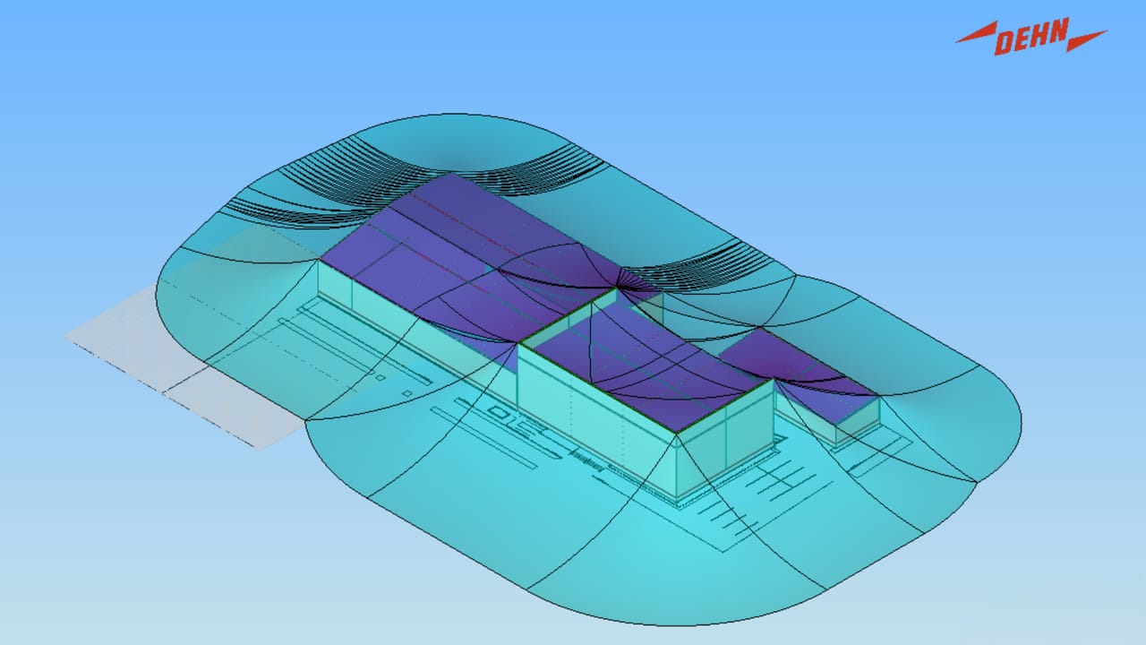
Understand the rolling sphere method in LPS design, how it defines protected volume, when to apply it, and its relationship with air terminals, separation distance, grounding, SPDs, and NBR 5419.
Check it out!
The LPS rolling sphere is a technical method used to verify the protected volume created by the air-termination system in lightning-protection designs. It helps identify points on a structure that may be exposed to direct lightning strikes and guides the positioning of air terminals, elevated conductors, meshes, and natural components.
Within the context of ABNT NBR 5419, the rolling sphere method is especially relevant for buildings with complex geometries, technical rooftops, protruding equipment, antennas, metallic structures, mechanical rooms, photovoltaic systems, CCTV, telecommunications, and height differences.
This article explains how the method works, when to apply it, which precautions to consider, and why the rolling sphere does not replace a complete LPS design. For an overview of the standard, also see NBR 5419: LPS, risk assessment, grounding, SPDs, and technical documentation.
What Is the Rolling Sphere Method in an LPS?
The rolling sphere method considers an imaginary sphere, with a radius defined by the LPS protection level, rolled over and around the structure in all relevant directions.
Points touched by the sphere are considered susceptible to direct lightning impact. Therefore, these points must be protected by elements of the air-termination subsystem, such as rods, cables, mesh conductors, isolated air terminals, or natural components that meet the applicable criteria.
In simplified terms:
- if the sphere touches a point on the structure, that point may be exposed to direct impact;
- if the sphere touches only air-termination elements, the analyzed point lies within the protected volume;
- if rooftop equipment is touched by the sphere, it should not be considered protected merely because it is close to a rod or mesh;
- even if an element lies within the protected volume, down conductors, grounding, separation distance, equipotential bonding, and surge-protection measures still need to be assessed.
Technical Basis of the Rolling Sphere Method
The rolling sphere method is based on the electrogeometric model of lightning. In a cloud-to-ground discharge, a downward leader propagates from the cloud toward the ground. As it approaches the surface or a structure, the local electric field increases.
When the dielectric strength of air is exceeded, an upward leader may form from a point on the structure, the ground, or a protruding element. The point from which this upward leader connects to the downward leader defines the final strike point.
The shortest distance between the head of the downward leader and the origin point of the upward leader is called the striking distance or final connection distance. In the rolling sphere method, this distance is represented by the sphere radius.
The approximate relationship between lightning peak current and striking distance can be expressed as:
r = 10 · I^0,65
where:
r = sphere radius, in meters
I = lightning peak current, in kA
This relationship shows that sphere radius is associated with the minimum current the air-termination system must be able to intercept within a given protection level. The lower the current considered, the shorter the striking distance and therefore the smaller the sphere radius.
Protection Level and Rolling Sphere Radius
Classification into protection levels establishes standardized radii for practical application of the method:
| LPS protection level | Rolling sphere radius | Associated minimum current |
| I | 20 m | 3 kA |
| II | 30 m | 5 kA |
| III | 45 m | 10 kA |
| IV | 60 m | 16 kA |
The technical interpretation is that protection level I, by using a smaller-radius sphere, identifies more potentially exposed points and requires a more restrictive air-termination arrangement. Level IV, with a larger radius, corresponds to a less severe requirement.
The protection level should not be selected visually. It must result from risk assessment in accordance with NBR 5419-2.
Need to validate the protected volume of a rooftop?
A3A Engenharia develops LPS Designs with risk assessment, air-termination definition, down conductors, grounding, equipotential bonding, technical documentation, and professional responsibility records.
How to Apply the Rolling Sphere Method to a Building
In practical application, the sphere must be rolled around and over the structure to be protected. Every point touched by the sphere is considered a potential direct-strike point and must be protected by elements of the air-termination subsystem.
The sphere center conceptually represents the position of the downward leader head. Points on the structure touched by the sphere represent locations from which an upward leader could develop and establish the final connection with the lightning discharge.
When the sphere is applied to an irregular structure, it may touch edges, corners, parapets, roofs, towers, upper façades, and protruding equipment. This demonstrates why the method is relevant for buildings with complex geometry.
Sphere Penetration Between Air Terminals
An important aspect is sphere penetration between air terminals. When two rods, two masts, or two parallel conductors are spaced apart, the sphere can penetrate between them. This penetration influences the required height of the air terminals used to protect equipment located between the air-termination elements.
For two air terminals or two parallel conductors, penetration depth can be calculated from the geometric relationship:
p = r - √(r² - (d/2)²)
where:
p = sphere penetration depthr = rolling sphere radiusd = distance between air terminals or parallel conductors
Air-terminal height must be compatible with the calculated penetration and with the height of the object to be protected. Otherwise, the sphere may touch the equipment or structure between the air terminals.
When Should the Rolling Sphere Method Be Applied?
The rolling sphere method is applicable to determining the protected volume of the external LPS and is especially useful when the building geometry is not simple.
| Situation | Why it requires attention |
| Rooftop mechanical rooms | They may rise above the roof plane and remain outside protection provided by perimeter meshes. |
| Antennas, masts, and telecommunications | They are elevated elements and usually have cables connected to the interior of the building. |
| CCTV cameras and security systems | They may be located on masts, façades, or exposed edges, with data and power cables. |
| Chillers, exhaust fans, and HVAC equipment | They have metallic enclosures, electrical supply, and control systems. |
| Photovoltaic panels | They alter roof geometry and introduce metallic structures and DC/AC cables. |
| Parapets and raised edges | They may become strike points if not correctly protected. |
| Metal roofs | They require assessment of continuity, thickness, perforation risk, and function as a natural component. |
| Tall buildings | They may require analysis of side flashes and protection at upper levels. |
Technical Rooftops: Where the Method Adds the Most Value
The rolling sphere method adds the most value when protruding rooftop elements are present. A perimeter mesh or nearby air terminal does not always adequately protect elevated equipment, especially when there are height differences, spacing between air terminals, or cables connected to the building interior.
Equipment may be inside the protected volume against direct impact and still require additional measures. This occurs because many devices have electrical, metallic, or communication connections to the interior of the building.
If the separation distance is not maintained, dangerous sparking can occur between the external LPS and internal conductive parts. In addition, partial lightning currents may be conducted through power, data, control, or functional-grounding cables.
Do you have rooftop equipment, CCTV, antennas, HVAC, or photovoltaic systems?
Rolling sphere assessment must be coordinated with separation distance, equipotential bonding, SPDs, data lines, and internal systems. Learn about Surge Protection Measures.
Rooftop Equipment: Correct Assessment
| Rooftop element | Common error | Correct assessment |
| Antenna | Connecting it to the LPS without assessing partial currents. | Verify protected volume, isolated air termination, equipotential bonding, and SPDs on cables. |
| CCTV camera | Assuming the mast protects the camera. | Assess an air terminal above the equipment and protection on data and power cables. |
| Chiller or exhaust fan | Considering only the metallic enclosure. | Assess electrical supply, automation, separation distance, and equipotential bonding. |
| Photovoltaic panels | Installing modules without reviewing the existing LPS. | Verify protected volume, distances, equipotential bonding, and surge protection. |
| Mechanical room | Protecting only the slab perimeter. | Assess elevated geometry and potential points touched by the sphere. |
Isolated Air Termination: When Should It Be Considered?
Isolated air termination may be considered when lightning current must be prevented from circulating through metallic parts, equipment, or internal building systems. This may apply to sensitive equipment, antennas, masts, photovoltaic systems, special metallic structures, or situations where the separation distance must be preserved.
In these cases, the rolling sphere method helps verify whether the isolated air terminal creates the required protected volume without requiring an inappropriate direct connection to the protected equipment.
Metal Roofs, Parapets, and Natural Components
Metal roofs, parapets, metallic structures, and other building elements may act as natural LPS components provided they meet the applicable technical criteria. The rolling sphere helps verify whether these elements are part of the protected volume or remain exposed to direct strikes.
This assessment cannot be purely visual. Electrical continuity, thickness, connections, perforation risk, integration with down conductors, grounding, and documentation must be verified.
Separation Distance: What the Rolling Sphere Does Not Solve by Itself
The rolling sphere guides air termination but does not solve separation distance by itself. Even if a point is protected against direct impact, there may be a risk of sparking between the external LPS and internal metallic parts, cables, cable trays, ducts, or equipment.
Therefore, the design must assess integration among air termination, down conductors, grounding, equipotential bonding, internal LPS, and surge-protection measures. For protection of internal systems, see NBR 5419-4: internal LPS, SPDs, and protection of electrical and electronic systems.
Common Errors When Applying the Rolling Sphere Method
Common errors include:
- treating the rolling sphere as an illustrative drawing without technical analysis;
- failing to relate sphere radius to the adopted protection level;
- protecting only the main roof and ignoring technical volumes;
- assuming a camera, antenna, or exhaust fan is protected merely because it is close to an air terminal;
- failing to assess sphere penetration between air terminals;
- ignoring separation distance;
- failing to coordinate air termination with down conductors and grounding;
- failing to assess SPDs and lines connected to rooftop equipment;
- failing to document application of the method in the design.
How to Document Application of the Method in an LPS Design
In professional designs, rolling sphere application must be demonstrable. This is important for technical review, coordination, inspection, maintenance, and issuance of technical reports.
| Documentation item | Purpose |
| Adopted protection level | Justifies sphere radius and other air-termination parameters. |
| Risk-assessment report | Demonstrates the criterion used to define the protection level. |
| Roof plan with air terminals | Shows the location of air-termination elements. |
| Sections or three-dimensional model | Facilitates validation of protected volume in complex geometries. |
| Identification of rooftop equipment | Allows verification of antennas, HVAC, CCTV, PV, and mechanical rooms. |
| Separation-distance verification | Controls the risk of dangerous sparking. |
| Integration with down conductors and grounding | Confirms continuity of current conduction. |
| Interfaces with internal LPS and SPM | Indicates the need for equipotential bonding, SPDs, and protection of internal systems. |
During inspections, upgrades, or issuance of an LPS technical report, this documentation helps identify whether the building remains compatible with the original design or whether rooftop changes require reassessment.
Do you have an old design or recent rooftop changes?
A3A Engenharia performs LPS Inspection, document analysis, verification of air termination, down conductors, grounding, SPDs, and recommendations for upgrades based on technical evidence.
Conclusion
The rolling sphere method is an essential technical tool for defining the protected volume of an external LPS. Its application is especially relevant in buildings with complex geometries, technical rooftops, and protruding elements, where simplified methods may not reveal all exposed points.
At the same time, the method should not be treated as a complete lightning-protection solution. It guides air termination, but LPS performance depends on integration with down conductors, grounding, equipotential bonding, separation distance, internal LPS measures, and surge protection.
In industrial facilities, corporate campuses, data centers, substations, and critical buildings, correct analysis of the protected volume should be performed together with risk assessment and evaluation of internal systems connected to the roof.
Technical References
[1] ABNT. ABNT NBR 5419-1: Protection against lightning — Part 1: General principles. Rio de Janeiro: Associação Brasileira de Normas Técnicas.
[2] ABNT. ABNT NBR 5419-2: Protection against lightning — Part 2: Risk management. Rio de Janeiro: Associação Brasileira de Normas Técnicas.
[3] ABNT. ABNT NBR 5419-3: Protection against lightning — Part 3: Physical damage to structures and life hazard. Rio de Janeiro: Associação Brasileira de Normas Técnicas.
[4] ABNT. ABNT NBR 5419-4: Protection against lightning — Part 4: Electrical and electronic systems within structures. Rio de Janeiro: Associação Brasileira de Normas Técnicas.
Frequently Asked Questions
The rolling sphere method is a verification method used in LPS designs to assess regions exposed to direct lightning strikes and assist in positioning air terminals and air-termination elements.
No. It is not a type of LPS, but a method for analyzing the protected zone. It can be applied with Franklin rods, meshes, Faraday cages, and other air-termination arrangements.
The method is especially useful in buildings with complex geometries, height differences, technical volumes, rooftop equipment, antennas, tanks, metallic structures, and situations where the protected zone needs technical verification.
A Franklin air terminal is an air-termination element. The rolling sphere can be used to verify whether the position and height of air terminals adequately protect vulnerable points on the building.
No. Risk assessment defines the need for protection and the protection level. The rolling sphere is used during external LPS design to assess the protected zone and the arrangement of air terminals.
Additional Technical Materials
NBR 5419 and LPS Cluster
- NBR 5419: LPS, Risk Assessment, Grounding, SPDs, and Technical Documentation
- NBR 5419-1: General Principles of Lightning Protection
- NBR 5419-2: Risk Assessment in LPS Designs
- When Does a Building Need an LPS?
- External LPS: Air Termination, Down Conductors, and Grounding in NBR 5419-3
- NBR 5419-4: Internal LPS, SPDs, and Protection of Electrical and Electronic Systems
- Types of LPS: Franklin, Faraday Cage, Rolling Sphere, and NBR 5419
- Franklin Air Terminal in LPS: Lightning Rod, Faraday Cage, and Air-Termination System
Grounding, Equipotential Bonding, and SPDs
- LPS Grounding: Function in NBR 5419-3 and External LPS
- Grounding Grid: Design Criteria, LPS, and Equipotential Bonding
- Equipotential Bonding or Potential Equalization
- SPDs: Surge Protection, NBR 5410, LPS, and Grounding
- SPD Coordination
- SPDs for Data Lines, CCTV, Automation, and Telecommunications
Related Solutions
- Lightning Protection
- Grounding and Equipotential Bonding
- Surge Protective Devices
- Surge Protection Measures
- Low-Voltage Electrical Installations
