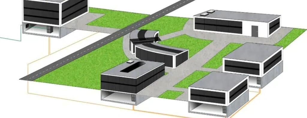
Learn how to design an optical fiber backbone with topology, route redundancy, fiber type, optical distribution frames, optical budget, testing, documentation, and acceptance criteria.
Check it out!
An optical fiber backbone is the primary network infrastructure used to interconnect racks, technical rooms, buildings, data centers, remote units, substations, power plants, dams, IP CCTV systems, automation, and critical telecommunications.
In corporate projects and mission-critical environments, the backbone should not be treated merely as cable installation. It is part of the telecommunications architecture and requires definition of topology, routes, redundancy, fiber type, optical distribution frames, splices, optical budget, certification, documentation, and technical acceptance criteria.
This article explains what a network backbone is, how an optical backbone is designed, which topologies can be used, and which criteria should be considered in network and telecommunications infrastructure projects.
Summary: Optical Backbone in Network Design
| Item | Role in the design | Technical criteria |
|---|---|---|
| Optical backbone | Interconnects distributors, racks, buildings, technical rooms, and remote units | Capacity, distance, topology, redundancy, and availability |
| Topology | Defines how network points will be interconnected | Star, ring, mesh, redundant routes, and independent physical paths |
| Optical distribution frames and terminations | Organize and protect fibers, splices, pigtails, and optical cords | Identification, maintenance, expansion, and traceability |
| Optical budget | Calculates optical-link losses | Distance, splices, connectors, transceivers, and technical margin |
| Certification | Validates losses, continuity, performance, and documentation | Optical tests, OTDR, technical report, and infrastructure acceptance |
Importance of the Optical Fiber Backbone in Network Design:
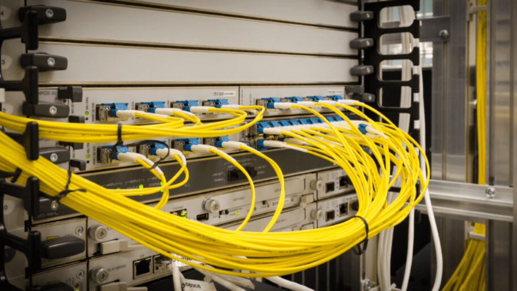
The optical fiber backbone is fundamental to ensuring that network infrastructure provides high performance and scalability, serving the needs of both small business environments and large corporations and service providers.
Below are some reasons why a fiber backbone is essential in a Network Design:
- High Data-Transmission Capacity Optical fiber offers significantly greater bandwidth than copper cables, allowing large volumes of data to be transmitted simultaneously. In environments such as data centers or corporate campuses, where very large amounts of data traverse the network, the optical fiber backbone helps ensure communication between different points without congestion or bottlenecks.
- Low Latency and Signal Loss Because of the nature of optical transmission, fiber minimizes signal loss even over long distances, which is important for keeping data traffic fast and efficient without excessive degradation along the path. This makes the optical fiber backbone an appropriate choice for networks that require low latency, such as streaming systems, real-time communications, and high-demand critical networks.
- Immunity to Electromagnetic Interference (EMI) Unlike copper cables, which can be affected by electromagnetic interference from nearby devices or cables, optical fiber is immune to this coupling in the transmission medium. This is especially important in industrial and corporate environments where electrical equipment can affect signal quality.
- Scalability and Flexibility An optical fiber backbone facilitates network expansion and reconfiguration as project requirements grow. As new technologies are implemented and bandwidth demand increases, the fiber backbone can support higher transmission rates through compatible optics and architecture, helping the network continue operating efficiently.
- Security and Reliability Optical fiber does not radiate electromagnetic signals in the same way as metallic media and can reduce some interception risks, but security still depends on physical protection and architecture. In corporate and government networks, fiber is frequently preferred for backbone links. Properly executed splices and protected terminations also contribute to durable and reliable connections.
Backbone Types: Applications and Scope in Network Infrastructure
A backbone can serve different functions and scales within a network depending on the environment, distance involved, and traffic volume. The main backbone types used in infrastructure projects include:
Building Backbone
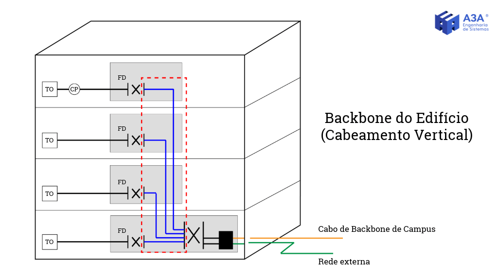
This internal backbone interconnects floors, shafts, and technical rooms within the same building. Usually implemented with optical or metallic cabling, it connects floor telecommunications racks to the Data Center or main equipment room (MDF).
Campus Backbone
It interconnects multiple buildings within the same site or complex — such as universities, hospitals, or industrial plants. It generally uses single-mode optical fiber with underground ducts, handholes, and mechanical protection to provide centralized, high-speed connectivity between buildings.
Internet Service Provider Backbone (ISP Backbone)
This is the core infrastructure of telecommunications operators, connecting local networks to Internet exchange points, servers, and national or international backbone infrastructure. It may involve long-distance optical fibers, DWDM networks, OLTs, and high-availability redundant systems.
Metropolitan Backbone (Metro Backbone)
This high-capacity network interconnects different points within a city or metropolitan region. Used by operators, public agencies, or large corporations, it supports service distribution to neighborhoods, substations, or remote units.
Industrial or Mission-Critical Backbone
This backbone is designed for environments with high requirements for availability, operational continuity, environmental exposure, and integration with automation, protection, CCTV, and telecommunications systems. The architecture may use a redundant star, ring, or mesh, while Ethernet redundancy protocols — such as RSTP, MRP, PRP, or HSR, where applicable — belong to the communications layer and should not be confused with the physical fiber topology. Cable selection, routes, and mechanical protection depend on the environment and project.
The backbone is one of the components of a structured cabling infrastructure. To understand how it integrates with other subsystems such as horizontal cabling, the work area, consolidation points, and telecommunications rooms, it is essential to understand the complete architecture defined by technical standards.
→ See how structured cabling subsystems are organized and the role of the backbone within a structured network →
Backbone Topology: Star, Ring, Mesh, and Redundancy
Physical topology should be selected according to availability requirements, distances, served points, criticality, maintenance, and expansion capacity. There is no universally superior topology: a simple star may be sufficient for an administrative building, while an industrial process or critical campus may require independent routes and equipment redundancy.
| Physical topology | Behavior | Typical application | Key consideration |
|---|---|---|---|
| Star | Each distributor connects to the central point | Buildings and campuses with a central core | Failure concentration at the central point |
| Star redundante | Each point can reach two cores or distributors | High-availability environments | Routes and equipment must be genuinely independent |
| Ring | Nodes form a closed path | Industrial plants and distributed networks | Recovery also depends on the protocol and active equipment |
| Mesh | Multiple paths exist between nodes | Selected critical infrastructures | Cost, fibers, ports, and operational complexity |
Logical Redundancy Does Not Replace Physical Route Diversity
Two links may appear redundant in the logical diagram and still share the same conduit, shaft, handhole, optical distribution frame, or cable section. In that case, a single excavation, fire, crushing event, or intervention can interrupt both paths simultaneously.
When continuity under a physical failure is required, the design must define Route A and Route B with independence compatible with the expected availability level. The analysis should include building entrances, shafts, underground pathways, handholes, rooms, optical distribution frames, and concentration points — not merely the number of fibers.
Backbone Pathways Between Buildings and Within the Building
ABNT NBR 16415 addresses indoor, underground, and aerial pathways for structured cabling. Between buildings, the design should consider environmental variations, water ingress, contamination, electromagnetic interference in metallic components, vibration, mechanical protection, drainage, and future expansion.
For underground pathways, the standard recommends considering access, pulling tension, installation method, and future expansion; it also recognizes the value of spare ducts and subducts to reduce future excavation. The backbone must be coordinated with civil works, electrical systems, LPS, drainage, landscaping, and other project utilities.
Optical Loss Budget: The Backbone Must Close Before Installation
The optical budget compares expected channel loss with the maximum loss supported by the application and transceivers. Under NBR 14565, channel attenuation is the sum of cable, connection, and splice losses. Additional connectors or splices may be introduced only if the power budget remains compliant.
| Component | NBR 14565 design reference | Effect on the budget |
|---|---|---|
| Fiber | Attenuation per km according to type and wavelength | Increases with length |
| Mated connection | Up to 0.75 dB per connection as a hardware limit | Each interface consumes margin |
| Splice | Up to 0.30 dB as a hardware limit | Additional splices consume margin |
| Engineering margin | Defined by the design/application | Accommodates aging and uncertainties |
The calculation should not automatically use normative maximum limits as the expected workmanship level. Design values and acceptance criteria may be more restrictive to preserve operating margin. The key is to define allowable losses before procurement and then verify them in the field.
Fiber Count: Capacity Is More Than the Number of Optical Pairs
Sizing the cable requires mapping current applications, redundant links, spare fibers, future expansions, speed growth, and possible parallel technologies. Spare fibers without identification or corresponding ports and optical distribution frames do not represent operational capacity.
In critical networks, it is advisable to clearly distinguish fibers in service, technical spares, redundancy, and planned expansion. Documentation should show origin, destination, tube, fiber, optical distribution frame, port, and associated service, enabling maintenance without relying on informal knowledge.
How Is an Optical Fiber Backbone Designed?
Within a network design, selecting the optical fiber depends on several factors that must be considered to ensure that the network can support current and future demands.
The following are some of the main points to consider in a backbone design:
- Fiber Type Selection: Two main types of optical fiber are used in backbones: single-mode and multimode.
Single-mode fiber is well suited to long distances and high transmission capacity and is common in metropolitan networks (MANs) and long-distance backbones. Multimode fiber is more appropriate for shorter distances and is frequently used in data centers and local area networks (LANs).
- Network Topology Choosing the network topology used in backbone implementation is another important factor. Star topology is widely used, with the backbone connecting several devices or local networks to a central point such as a core switch or main router. In large corporate networks or distributed environments, ring or mesh topologies may also be used to provide redundancy and high availability.
- Optical Fiber Splicing Optical fiber fusion splicing is widely used to create low-loss, mechanically protected backbone connections. Proper splicing preserves transmission integrity and provides a robust, durable joint.
- Fiber Pathways and Infrastructure Management Designing an optical fiber backbone also requires careful planning of the pathways through which fiber cables will be installed. In data centers and large buildings, this may include ducts, cable trays, and cable-management systems to organize and protect the fibers.
Optical Fiber Backbone Applications:
- Data Centers: Interconnection between server racks and core switches in data centers is commonly implemented through optical fiber backbones. This supports fast, reliable internal traffic with low latency and the high data volumes processed in these environments.
- University and Corporate Campuses: In distributed networks where different buildings or units must be connected, an optical fiber backbone provides the required performance for interbuilding data transmission.
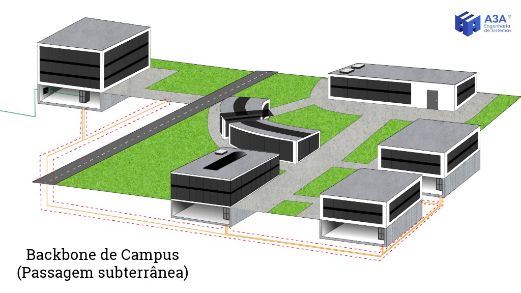
Collection: A3A Engenharia
- Internet Service Providers (ISPs): ISPs use optical fiber backbones to provide high-speed connectivity, allowing large volumes of data to travel long distances with low optical loss.
Main Fiber Types
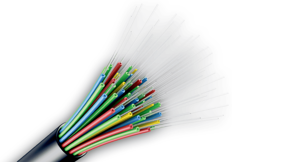
Fiber-type selection depends on the distances the backbone must cover, the required data-transmission rate, and the available budget.
There are two main optical-fiber groups: multimode fiber and single-mode fiber, each with specific characteristics that affect backbone applications.
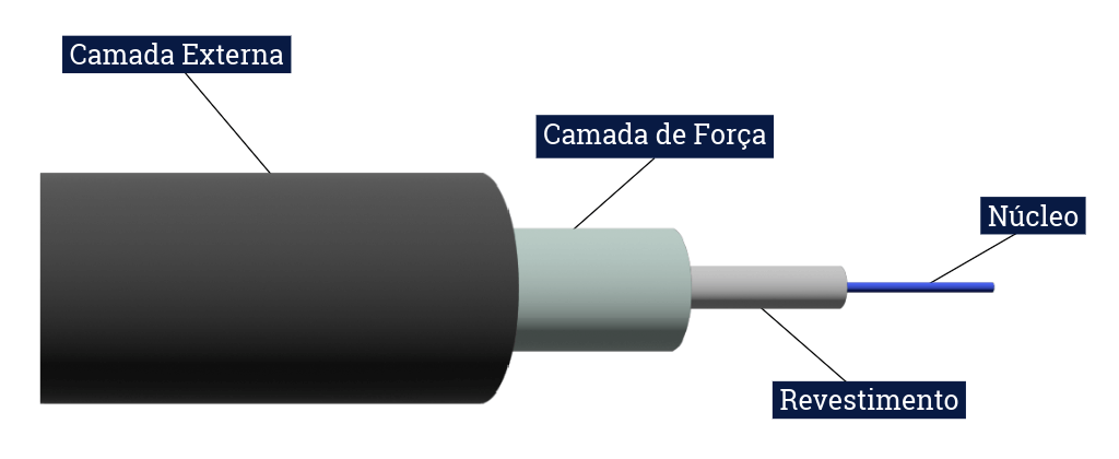
The main fiber types and their backbone applications are listed below.
1. Single-Mode Fiber (OS1 and OS2)
Single-mode fiber is designed for long-distance data transmission and has lower attenuation than multimode fiber. Its small core supports propagation with a single dominant mode, reducing modal dispersion.
- OS1/OS1a: single-mode cable categories mainly associated with indoor installation applications. Selection should consider the application, wavelength, attenuation coefficient, and cable environment.
- OS2: a low-attenuation single-mode category widely used in outside plant, campus, and longer-reach links. Supported distance is not a fixed property of the fiber; it depends on the application and transceiver. Within the building/campus cabling scope of NBR 14565, several single-mode applications are tabulated up to 2,000 m, while application standards may allow longer distances outside that scope.
2. Multimode Fiber (OM1, OM2, OM3, OM4, and OM5)
OM categories describe multimode-fiber performance characteristics but do not by themselves define a universal speed or distance. Reach results from the combination of fiber category, standardized application, wavelength, transceiver, and loss budget.
| Ethernet application | OM3 | OM4 | Note |
|---|---|---|---|
| 10GBASE-SR | 300 m | 400 m | Example channel in NBR 14565 |
| 40GBASE-SR4 | 100 m | 150 m | Multifiber application |
| 100GBASE-SR4 | 70 m | 100 m | Multifiber application |
OM1 and OM2 remain relevant in installed bases but normally provide less margin for high-speed Ethernet applications. OM3 and OM4 are common in corporate environments and data centers. OM5 adds wideband performance for applications using multiple wavelengths in the multimode range; its adoption should be justified by the architecture and intended transceivers.
3. How to Select the Fiber Type for the Backbone
The choice between single-mode and multimode fiber depends on the network design requirements:
- Distance: If the backbone must cover long distances, such as metropolitan networks (MANs) or links between distant buildings, single-mode fiber (OS1 or OS2) is generally more appropriate because of its low attenuation and long-reach capability.
- Transmission Rate: If the priority is high-speed data transmission over short distances, such as in data centers or large offices, multimode fiber (OM3, OM4, or OM5) can offer a favorable cost/performance ratio and support very high transmission rates (up to 100 Gbps over short distances, depending on the standardized application).
- Budget: Multimode fiber may reduce optics cost in some short-reach applications. For long distances, however, single-mode fiber is more efficient and avoids intermediate regeneration that would otherwise be required.
Advantages of Using an Optical Fiber Backbone
- Scalability and support for high speeds: optical fiber provides substantial growth capacity for high-speed Ethernet and Fibre Channel applications, including 100 Gbit/s and higher rates when fiber type, transceivers, topology, and optical budget are compatible with the application.
- Immunity to interference: optical fiber is immune to electromagnetic coupling in the transmission medium, avoiding signal degradation caused by nearby electrical equipment or power systems.
- Long distances with low attenuation: single-mode fiber supports long-reach applications with low attenuation. Actual distance depends on the optical application, transceivers, amplification/regeneration strategy, and loss budget.
Optical Fiber and Electromagnetic Compatibility
Using optical fiber in network projects offers advantages not only for high-speed and long-distance transmission but also because a dielectric optical medium is immune to electromagnetic interference and does not provide a conductive data path between endpoints. This is particularly relevant when interconnecting buildings with different electrical environments or in areas with significant lightning exposure.
Avoiding Conducted Transient Currents and Lightning-Related Effects
When communication networks use copper cables, lightning and related electromagnetic effects can induce transient currents and potential differences in metallic paths. In industrial areas or large buildings with higher exposure, these phenomena can cause interference, outages, or equipment damage.
A fully dielectric optical fiber does not create a conductive data path between buildings, which is a relevant advantage where potential differences, electromagnetic interference, and surge exposure exist. This does not mean that every optical installation is automatically protected against lightning: cables may contain metallic elements, pathways and enclosures may be metallic, and active equipment still depends on appropriate power, grounding, equipotential bonding, and electrical protection.
Electromagnetic Compatibility (EMC) and Different Electrical Environments
When interconnecting buildings with different electrical conditions, electromagnetic compatibility (EMC) is an important design concern. Electrical equipment can generate electromagnetic fields that couple into metallic communication cabling. Optical fiber is immune to this coupling in the transmission medium, allowing communication between buildings without this form of interference even when electrical systems differ or industrial machinery is present.
This immunity makes optical fiber particularly suitable for industrial, corporate, and other environments with high electromagnetic exposure. The final decision should also consider distance, application, availability, pathways, optical-system cost, and maintenance requirements.
Relationship With the Lightning Protection System (LPS)
Interconnecting buildings with different electrical environments, especially in lightning-exposed areas, requires an appropriate Lightning Protection System (LPS) and equipotential bonding to provide an acceptable protection level for both electrical installations and communication systems. When the network uses copper cabling, additional measures such as grounding and Surge Protective Devices (SPDs) may be required to manage lightning-related surges.
A fully dielectric optical medium does not require surge protection in the same manner as a metallic data path because it does not conduct surge current between endpoints. This can simplify integration with the LPS and reduce a relevant damage path during storms. Active equipment and any metallic cable elements, however, still require appropriate protection.
Use of Surge Protective Devices (SPDs)
For metallic links, surge protection should be analyzed within the electrical, grounding, and LPS design. In fully dielectric optical links, the transmission medium does not conduct the surge between endpoints, but this does not eliminate the need to protect power supplies for switches, transceivers, converters, racks, and other equipment. When an optical cable contains armor or another metallic element, those elements must also be addressed by equipotential-bonding and protection engineering.
In environments requiring LPS and SPDs for electrical systems, a fully dielectric optical link reduces the possibility of surge transfer through the interbuilding communication medium. Service continuity, however, still depends on the protection and availability of active equipment, power supplies, switches, transceivers, and associated systems.
In optical-backbone designs for corporate buildings, campuses, data centers, substations, power plants, dams, and industrial environments, topology definition should consider availability, independent routes, capacity, certification, documentation, and maintenance.
Also see the content on telecommunications design, optical networks, and engineering consulting to structure the backbone as critical infrastructure rather than merely cable installation.
How Should an Optical Fiber Backbone Be Tested and Certified?
Backbone acceptance should demonstrate that the installed infrastructure meets the loss budget, maintains polarity, and contains no events incompatible with the design. ABNT NBR 16869-2 organizes inspection and test methods for installed optical cabling and distinguishes end-to-end attenuation measurement from characterization of events along the link.
| Test | What it answers | Use in acceptance |
|---|---|---|
| LSPM/OLTS | What is the total link loss? | Compare measured attenuation with the design/application limit |
| OTDR | Where are connectors, splices, bends, and events located? | Characterize the link and locate anomalies |
| Connector inspection | Are end faces clean and intact? | Avoid loss and damage caused by contamination |
| Polarity/continuity | Do fibers reach the correct positions? | Confirm correspondence between origin and destination |
For multimode fiber, NBR 16869-2 uses 850 nm and 1,300 nm; for single-mode fiber, 1,310 nm and 1,550 nm. For OTDR, the method uses a launch fiber and a receive/terminal cord so that the initial and final interfaces can be evaluated. In complex configurations, bidirectional measurements are important to reduce the influence of backscatter differences.
The standard also explicitly does not accept marginal results in optical-cabling tests. The link must meet the defined criterion or be corrected and retested.
What Should Be Included in the Optical Test Report?
- link and fiber identification;
- fiber type and OM/OS category;
- tested wavelengths;
- test configuration and method;
- equipment manufacturer, model, serial number, and calibration;
- connector and adapter characteristics;
- reference used in the test;
- measurement direction where applicable;
- date, time, and operator;
- measured results and compliance criterion.
Procurement: How to Equalize Cables, Optical Distribution Frames, and Optical Connectivity?
Backbone procurement should not be equalized only by “fiber count” and price per meter. The technical comparison must verify fiber category, cable construction, indoor/outdoor environment, fire performance, armor or dielectric characteristics, bend radius, tensile load, connectors, pigtails, optical distribution frames, trays, capacity, documentation, and transceiver compatibility.
| Group | Equalization criteria |
|---|---|
| Cable | OM/OS, construction, environment, fiber count, bend radius, tensile load, protection, and certifications |
| Optical distribution frame | Capacity, rack/U, trays, entries, adapters, expansion, and identification |
| Pigtails | Fiber type, connector, polish, length, and performance |
| Patch cords | Fiber, polarity, connectors, length, and traceability |
| Transceivers | Application, wavelength, reach, optical power, and compatibility |
| Service | Splicing, inspection, cleaning, testing, reports, As-Built documentation, and warranty |
Backbone Commissioning and Acceptance
O aceite deve combinar inspeção física, conferência documental e ensaios. É necessário verificar rotas, reservas, identificação, Optical distribution frames, bandejas, raios de curvatura, fusões, conectores, polaridade, perdas e correspondência com o as built. Em backbones redundantes, a validação deve confirmar também se as rotas construídas mantiveram a diversidade física prevista em projeto.
When the backbone serves critical systems, commissioning may include functional tests with active equipment, simulation of a path loss, validation of protocol convergence, and confirmation that failure of one route does not simultaneously remove the redundant route.
Optical Backbone Design Deliverables
- architecture and topology diagram;
- route and pathway drawings;
- optical-budget calculation memorandum;
- fiber matrix by origin, destination, and service;
- especificações de cabos, Optical distribution frames, conectores e acessórios;
- rack elevation and occupancy;
- splice and fusion plan;
- identification and administration criteria;
- test plan and acceptance criteria;
- LSPM/OLTS and OTDR reports where applicable;
- As-Built documentation and final inventory.
Conclusion
The optical fiber backbone is the primary interconnection layer of network infrastructure. It connects distributors, racks, technical rooms, buildings, data centers, and remote units, supporting data traffic, IP CCTV, automation, access control, telecommunications, and mission-critical systems.
In corporate and industrial projects, the backbone should be defined by engineering criteria: topology, redundancy, physical routes, fiber type, optical budget, optical distribution frames, splices, transceivers, certification, documentation, and technical acceptance criteria.
When the network connects critical assets, technical rooms, power plants, dams, substations, or remote units, engineering consulting helps turn the optical backbone into planned, traceable, testable infrastructure aligned with operational requirements.
Technical References
[1] ABNT. ABNT NBR 14565:2019 — Structured cabling for commercial buildings. Rio de Janeiro: ABNT, 2019. Available at: https://www.abntcatalogo.com.br/
[2] ABNT. ABNT NBR 16415:2021 — Pathways and spaces for structured cabling. Rio de Janeiro: ABNT, 2021. Available at: https://www.abntcatalogo.com.br/
[3] ABNT. ABNT NBR 16869-2:2021 — Structured cabling — Part 2: Optical testing. Rio de Janeiro: ABNT, 2021. Available at: https://www.abntcatalogo.com.br/
[4] ISO/IEC. ISO/IEC 11801-1:2017 — Information technology — Generic cabling for customer premises — Part 1: General requirements. Available at: https://www.iso.org/standard/66182.html
[5] ISO/IEC. ISO/IEC 14763-3:2024 — Implementation and operation of customer premises cabling — Part 3: Testing of optical fibre cabling. Available at: https://www.iso.org/standard/89632.html
[6] TELECOMMUNICATIONS INDUSTRY ASSOCIATION. ANSI/TIA-568.3-E — Optical Fiber Cabling and Components Standard. 2022. Available at: https://tiaonline.org/standardannouncement/tia-issues-updated-optical-fiber-cabling-component-standard-ansi-tia-568-3-e/
Frequently Asked Questions
An optical fiber backbone is the primary network infrastructure used to interconnect distributors, racks, technical rooms, buildings, data centers, and remote units. It concentrates the network’s higher-capacity links.
The backbone interconnects the main points of the network infrastructure, such as telecommunications rooms, racks, distributors, data centers, buildings, and remote areas, allowing traffic between different network segments.
Optical fiber should be evaluated when there are long distances, high-capacity requirements, interbuilding links, data centers, industrial environments, electromagnetic interference, or higher network-availability requirements.
Topology depends on project requirements. Simple networks may use a star. Critical environments may require ring, mesh, redundant routes, or independent physical paths to increase availability and resilience.
An optical budget calculates link losses considering distance, connectors, splices, optical distribution frames, transceivers, and technical margin. It verifies whether the link will operate within the limits of the optical equipment.
Validation may include inspection, link identification, loss testing, OTDR, verification of optical distribution frames, connectors, splices, technical reporting, and comparison with the acceptance criteria defined by the design.
Additional Technical Materials
Related Solutions
Related Services
Main Content on the Topic
- Optical Fiber in Network Design
- Optical Distribution Frame: What It Is and Its Role in Optical Networks
- Optical Fiber Fusion Splicing
- NBR 14565
