
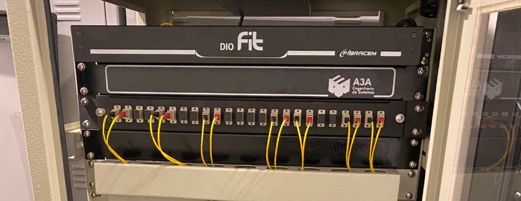
Learn how an optical distribution frame works, how to size capacity, choose LC/SC and UPC/APC, manage splices, polarity, loss budget, testing and acceptance.
Check it out!
The optical distribution frame (DIO) is connecting hardware used to terminate, protect, organize, and administer optical fibers in racks, telecommunications rooms, equipment rooms, data centers, and backbones. It can accommodate optical cables, splice trays, fusion protectors, pigtails, adapters, and the interfaces to which optical patch cords are connected before reaching switches, routers, OLTs, transmission equipment, or other systems.
In a professional installation, the DIO is not simply a “fiber box.” It is part of the optical link and must be compatible with fiber type, connector standard, polarity, fiber count, splice plan, loss budget, available rack space, identification, and the test method defined for acceptance. A seemingly simple DIO can therefore limit expansion, increase loss, make maintenance difficult, or prevent coherent certification when selected without engineering.
This article explains what a fiber-optic DIO is, how it works, which components form part of it, how to size capacity and spare fibers, when to use LC, SC, UPC, or APC, how to control polarity and loss, and which evidence should be required during installation and commissioning.
Fiber-Optic DIO: Quick Summary
| Item | Design function | Technical impact |
|---|---|---|
| DIO | Termination, organization, and protection of optical fibers | Improves maintenance, traceability, and network expansion |
| Splice trays | Accommodate fusion splices and protect optical joints | Reduce breakage risk and losses caused by improper handling |
| Adapters and pigtails | Provide standardized connection to optical patch cords | Organize the interface between the backbone and active network equipment |
| Rack or technical room | Physical installation environment for the DIO | Requires organization, identification, accessibility, and documentation |
| Optical certification | Validates loss, splices, connectors, and link performance | Provides the basis for technical acceptance and reliable operation |
Is the DIO Just a Piece of Equipment or Part of the Optical-Network Design?
Physically, the DIO is a passive component available in different capacities, formats, and configurations. However, purchasing the equipment alone does not determine whether the optical infrastructure will be organized, expandable, certifiable, and compatible with the systems it supports.
In a professional network, the DIO should be specified as part of the optical link. The design determines how many fibers will be terminated, which will remain as spares, the fiber and connector types, link distribution, allowable loss, rack occupancy, identification, testing, and the documentation required for operation and maintenance.
| Purchasing decision | Engineering decision |
|---|---|
| Nominal fiber capacity | Number of active fibers, spares, and expansion capacity |
| Rack- or wall-mounted model | Installation location, accessibility, rack occupancy, and environment |
| Adapter type and quantity | Connector standard, polarity, compatibility, and allowable loss |
| Supplied trays and accessories | Splice plan, fiber routing, bend radius, and mechanical protection |
| Component unit price | Lifecycle cost, maintenance, testing, documentation, and future expansions |
This distinction allows introductory DIO content to lead naturally to broader topics such as Optical Networks, Fiber-Optic Backbone e Telecommunications Design.
DIO, Splice Enclosure, Optical Patch Panel, and ODF: What Is the Difference?
Commercial terminology varies among manufacturers, but engineering function helps distinguish the equipment. A DIO is typically installed indoors and provides an organized termination and patching interface. An optical splice enclosure is primarily intended to protect splices, often along routes, shafts, pull boxes, or outdoor environments. Terms such as optical patch panel, optical panel, and ODF — Optical Distribution Frame may refer to distribution families with different densities and formats.
| Element | Primary function | Typical use | Patching interface |
|---|---|---|---|
| DIO | Terminate, protect, identify, and distribute fibers | Rack, telecommunications room, equipment room | Usually yes |
| Optical splice enclosure | Protect splices and branches | Indoor/outdoor routes, shafts, outside plant | Not always |
| Optical patch panel | Provide optical ports for administration | Racks and cabinets | Yes |
| ODF / optical frame | Higher-scale, higher-density optical distribution | Central facilities, data centers, telecom, and high-capacity installations | Yes |
There is no engineering benefit in choosing the “most robust-sounding” name. The design should specify the required function: how many fibers need termination, how many splices require protection, how many ports must remain available for patching, what density is acceptable, and how the assembly can be accessed without disturbing fibers already in service.
What Are the Main Types of DIO?
DIO type is defined mainly by mounting location, density, access method, and termination architecture. The nominal capacity advertised by the manufacturer should not be considered in isolation.
19-Inch Rack-Mount DIO
This is the most common configuration in technical rooms and data centers. It may occupy 1U, 2U, or more rack units and may use a sliding tray, drawer, removable cover, or front modules. The criterion is not simply saving rack units: high density without sufficient space for patch cords and tray access can increase operational risk.
Wall-Mount DIO
It is used when optical termination occurs outside a rack or where the environment has a small number of fibers. It should provide adequate incoming-cable retention, splice protection, bend-radius control, access to ports, and enclosure protection suitable for the environment.
Modular or High-Density DIO
It uses replaceable modules, cassettes, or adapter plates to support different interfaces and densities. This is useful when infrastructure grows in stages or when LC duplex, MPO/MTP, and other interfaces coexist. Modularity should be evaluated together with spare-part availability, maintenance access, and standardization across sites.
Panels for Direct Fusion Splicing or Preterminated Systems
In conventional solutions, the optical cable is prepared in the field and fibers are fusion-spliced to pigtails. In preterminated systems, part of the termination arrives factory-assembled and may use modules or cassettes. The latter reduces field labor but requires rigorous control of length, polarity, interface, bend radius, transport, and component compatibility.
The technical value lies not only in the DIO itself, but in how it integrates the optical network.
Topology, capacity, loss, identification, testing, and expansion should be defined before components are purchased and installed.
What Is the Function of an Optical Distribution Frame?
The primary function of an optical distribution frame (DIO) is to preserve the integrity of optical connections by reducing the risk of fiber damage and protecting the termination environment.
The device acts as a termination point where fibers can be organized, protected, and distributed to different network segments.
These characteristics are fundamental to cabling-system durability, performance, and reliability, especially in large and complex projects.
In simplified terms, the DIO plays for fiber-optic network design the same role that a patch panel plays for twisted-pair cabling. It provides the interface between optical cabling and network equipment, supporting flexible configuration and maintenance of interconnections.
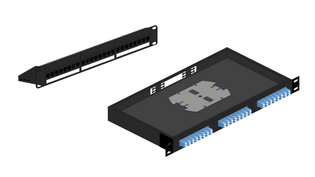
The optical distributor enables fibers to be routed according to network-application requirements. It may be rack-mounted or wall-mounted and is commonly used in telecommunications cabinets and equipment rooms.
How Does an Optical Distribution Frame (DIO) Work?
A DIO generally consists of a metal or durable polymer enclosure designed to house and protect optical fibers and related components.
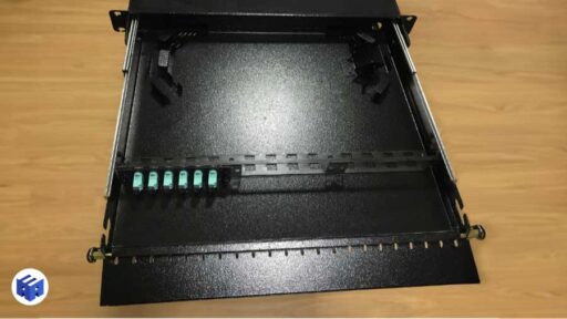
Its operation involves several key steps intended to provide a reliable, high-performance optical connection.
Fiber-Optic Fusion Splicing
When a fiber-optic cable reaches the DIO, it is prepared by removing the appropriate outer protective layers and preparing individual fibers for splicing.
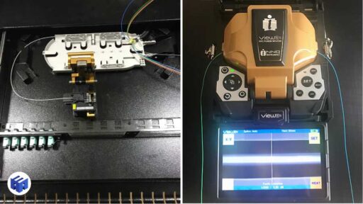
A fiber-optic fusion splicing is a process used to permanently join optical fibers. It is fundamental in distribution-panel termination because a properly executed fusion splice can provide low loss and low reflection compared with less controlled mechanical connections.
Splice Accommodation
After fusion splicing, fibers are carefully routed into the splice trays inside the DIO.
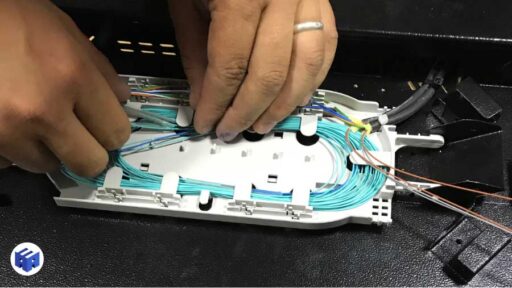
These trays organize and protect splices, reducing the risk of physical damage and facilitating future maintenance or network expansion.
Connection to Network Equipment
Once fibers are arranged, the next step is connection to optical adapters. These adapters provide standardized termination points that allow interconnection with network equipment.
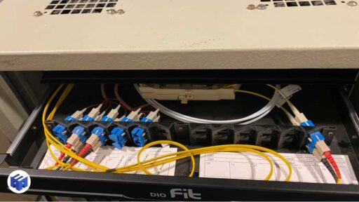
Equipment is connected using optical patch cords compatible with the DIO interfaces and with transceivers or transmission equipment. Media converters may exist in some architectures, but they are not part of the DIO and should not be confused with passive optical connectivity.
How Should DIO Capacity Be Sized?
Sizing begins with the number of fibers arriving at the distributor, but it does not end there. Fiber count, port count, simplex or duplex use, spare capacity, splice trays, pigtail space, planned growth, and rack occupancy all need to be related.
| Design question | What should be defined |
|---|---|
| How many fibers arrive at the DIO? | Cable capacity and number actually terminated |
| How many fibers will be used initially? | Active ports and operational spare capacity |
| Is the link simplex or duplex? | Relationship between physical fibers and service interfaces |
| Will there be expansion? | Reserved ports, plates, trays, and rack space |
| Will fibers be fusion-spliced to pigtails? | Number of splices, protectors, and tray capacity |
| Does more than one cable arrive at the panel? | Cable entries, retention, segregation, and identification |
| Which connector will be used? | Adapter plates, density, polish, and compatibility |
A DIO marketed as “24 fibers” can represent different architectures. With simplex connectors, there may be 24 individual positions; with LC duplex adapters, a plate may provide two fibers per physical adapter position. Specifications should therefore state the number of fibers, number of adapter positions, adapter type, and number of trays to avoid commercial ambiguity.
How Much Spare Capacity Should Be Reserved?
There is no universal percentage that replaces planning. Spare capacity should match the architecture, criticality, growth horizon, and difficulty of future intervention. In a campus or industrial environment, reserving dark fibers in the cable and free positions in the DIO may be more economical than installing a new backbone later. In a high-density rack, however, oversizing without evaluating working space can also create problems.
LC, SC, UPC, and APC: What Changes in the DIO?
LC and SC describe families of physical interfaces. UPC and APC describe the end-face polish of single-mode connectors. These are different criteria and should be specified separately. NBR 14565 requires connectors and adapters to be identified to prevent incorrect mating of fiber types and establishes common color coding: multimode in beige or black, single-mode PC in blue, and single-mode APC in green.
| Interface | Practical characteristic | Typical use | Design consideration |
|---|---|---|---|
| LC | Compact format and high density | Switches, data centers, higher-density racks | Control polarity and patch-cord access |
| SC | Larger format and simple handling | Optical distribution, telecom, and existing installations | Greater front-panel space per fiber |
| UPC / PC | Physical contact with polished end face | Data networks and various optical applications | Do not mate with APC |
| APC | Angled end face, typically identified in green | PON and reflection-sensitive applications | End-to-end compatibility and optical return loss |
Mating APC with a UPC/PC interface is a mechanical and optical incompatibility that can increase loss and reflection and damage connector end faces. The decision should be consistent across the entire chain: DIO adapter, pigtail, patch cord, splitter where present, and equipment interface.
Optical Polarity: Why Must the DIO Be Part of the Plan?
In duplex links, one fiber transmits and the other receives. NBR 14565 requires polarity to be maintained consistently throughout the system and positions to be identified. In the DIO, this means the position of each fiber, adapter, and patch cord cannot be the result of improvised field assembly.
When an installation uses duplex LC or SC connectivity, the design should define A/B orientation, numbering, port relationships, and patch-cord convention. In environments with multiple DIOs, the same logic should be maintained end to end. Optical continuity may exist and a service may still fail if transmit and receive fibers reach the wrong positions.
DIO Components and Associated Elements
The DIO integrates passive termination and organization components and connects to other elements of the optical system. To specify the assembly correctly, it is important to distinguish what is inside the distributor from what belongs to the channel or active equipment.
Optical Pigtails
Optical pigtails are short fiber-optic cables with a connector on one end and an unterminated fiber on the other. They are used to terminate fibers in splice enclosures, trays, or distribution panels.
The unterminated end is fusion-spliced to the main network fiber, creating a standardized connector interface and supporting low-loss, reliable transmission when correctly installed.
Optical Patch Cords
Optical patch cords are flexible cables with connectors at both ends. They connect the DIO to network equipment such as switches and routers and support operational patching and maintenance.
Splice Trays
Splice trays are components used inside a DIO to accommodate and organize optical-fiber splices. They protect splices from physical damage, support cable management, and facilitate maintenance or network expansion.
Optical Adapters
Optical adapters align and mate two optical connectors, providing stable connection points for fibers inside the DIO and facilitating interconnection between cabling and network devices.
Transceivers
Transceivers convert electrical signals to optical signals and vice versa. They are used in network devices such as switches and routers to transmit data over fiber. Although they are not internal DIO components, they are fundamental to optical communication between network devices.
Media Converters
Media converters are devices used to convert between optical and electrical/copper interfaces, allowing interoperability between different network media such as fiber optics and copper Ethernet. They connect equipment that uses different transmission technologies and are active devices separate from the DIO.
How Should a DIO Be Specified in a Fiber-Optic Design?
DIO specification should begin with network architecture rather than a commercially available model. The equipment should support planned capacity, allow safe maintenance, and preserve optical performance throughout the infrastructure lifecycle.
| Criterion | Design definition | Risk if omitted |
|---|---|---|
| Capacity | Active fibers, spares, ports, and future expansion | Early saturation or unnecessary oversizing |
| Format and installation | Rack, wall, rack units, front and rear access | Maintenance difficulty and conflicts with other equipment |
| Fiber type | Single-mode or multimode and applicable optical class | Incompatibility among cable, pigtail, and transceiver |
| Connectors and polish | LC, SC, UPC, or APC according to interfaces and application | Incompatible connections and increased reflection or loss |
| Splices and trays | Quantity, protection, routing, and spare capacity | Breakage, improper bends, and unsafe maintenance |
| Identification | Link code, origin, destination, fiber, port, and documentation | Poor traceability and longer intervention time |
| Loss budget | Limits for fiber, splices, connectors, and engineering margin | Installed link without sufficient margin for reliable operation |
| Testing and acceptance | Inspection, cleaning, OLTS, OTDR where applicable, and reports | Hidden faults and lack of technical evidence for acceptance |
The specification should also be coordinated with cable routes, racks, switches, optical modules, power, grounding, HVAC, and requirements of supported systems. For critical backbones, documentation should include diagrams, fiber identification, splice plan, loss budget, test results, and as-built records.
Loss Budget: How Much Loss Can the DIO Add to the Link?
The DIO does not have a single fixed loss value. Associated loss results from the connectors and splices included in the architecture. NBR 14565 establishes, as reference limits for structured-cabling connecting hardware, maximum attenuation of 0.75 dB for mated connectors and 0.3 dB for a splice. These values should not be treated as installation targets: well-executed projects normally use engineering margins and expected values below the maximums, based on components and application.
A link-loss budget should consider fiber length, attenuation coefficient at the applicable wavelength, all mated connections, all splices, and an engineering margin. Adding connectors, adapters, or patching points increases flexibility but consumes part of the optical budget. Permanent splices can reduce loss but decrease operational flexibility.
| Link element | What to consider | Impact |
|---|---|---|
| Optical fiber | Length, OM/OS type, and attenuation per kilometer | Distributed loss |
| Splices | Quantity and splice quality | Localized loss |
| Connectors/adapters | Quantity, cleanliness, alignment, and polish type | Loss and reflection |
| Optical patch cords | Fiber type, connectors, length, and condition | Part of the channel where applicable |
| Margin | Aging, maintenance, and tolerances | Reserve for reliable operation |
To determine whether a link supports 1 Gb/s, 10 Gb/s, 40 Gb/s, or another application, it is not enough to verify that “there is light.” The budget must be checked against application limits and the fiber class/type specified in the design.
How Should Fibers Be Organized Inside the DIO?
Internal organization should simultaneously protect the incoming cable, individual fibers, splices, and pigtails. The cable should be secured so mechanical loads are not transferred to the fibers. Spare loops should be stored without compression and in compliance with the manufacturer’s minimum bend radius.
- secure the optical cable properly at the panel entry;
- preserve strength members and mechanical strain relief according to cable construction;
- avoid unnecessary crossings between fibers and pigtails;
- place splice protectors in the intended tray positions;
- keep spare loops organized and accessible;
- do not close drawers or covers while compressing fibers;
- keep protective caps on unused optical ports;
- preserve bend radius during operation and maintenance, not only during installation.
In sliding DIOs, the behavior of pigtails and cables should be checked as the tray moves. An arrangement that appears correct with the drawer open may create tension or macrobends when closed.
Cleaning and Inspection of Optical Connectors
Dust, oil, residue, and scratches on a connector end face can increase attenuation and reflection and contaminate the opposing connector when mated. NBR 16869-2. This standard requires inspection of connector end faces used during testing and specifies cleaning and reinspection when contamination is present. IEC 61300-3-35 establishes visual inspection criteria for optical connectors; the cited edition is 2022.
The practice of “connecting to see if it works” before inspecting the interface can turn one clean port into two contaminated interfaces. In critical networks, the procedure should be systematic: inspect, clean when necessary, reinspect, and only then connect.
How Should Ports, Fibers, and Cables Be Identified in the DIO?
Identification should allow a person who did not participate in the installation to determine the origin, destination, and function of each link. NBR 16869-1 requires identifiers for cables, terminations, compartments, racks, panels, and other infrastructure elements and requires cables to be labeled at both ends.
In the DIO, a coherent identification structure should relate at least: DIO → position/port → fiber → cable → origin → destination. In larger installations, it is also useful to record fiber type, connector, port status, associated service, date of last change, and reference to the as-built drawing.
| Record | Example information |
|---|---|
| DIO | Identifier, rack, U position, room |
| Optical cable | Origin, destination, fiber count and type |
| Fiber | Number/color, origin port, destination port, status |
| Connector | LC/SC, PC/UPC/APC, simplex/duplex |
| Splice | Tray, position, fiber, and test record |
| Service | Switch/port, circuit, system, or application served |
How Should a Link Terminating in a DIO Be Tested and Certified?
Optical certification should verify the installed link, not only splice quality. NBR 16869-2 specifically addresses testing of installed optical cabling and covers single-mode and multimode fibers, connectors, adapters, splices, and other passive devices.
LSPM/OLTS: End-to-End Loss Measurement
A light source and power meter arrangement — LSPM, commonly implemented in OLTS certifiers — measures total attenuation of the link or channel according to the adopted reference configuration. NBR 16869-2 specifies multimode testing at 850 nm and 1,300 nm and single-mode testing at 1,310 nm and 1,550 nm. The reference method, test cords, and adapters contribute to measurement uncertainty and must be controlled.
OTDR: Event Location and Characterization
OTDR identifies events along the fiber such as connections, splices, macrobends, and breaks. To properly characterize interfaces at both ends, NBR 16869-2 provides for the use of a launch fiber and receive fiber/cord. For event measurements, testing in both directions may be necessary; bidirectional averaging reduces effects associated with backscatter differences between fibers.
OLTS/LSPM and OTDR are not interchangeable. The first primarily measures total power loss across the link; the second helps locate and characterize events. The test plan should define which evidence is required for project acceptance.
What Should Be Included in the Test Report?
NBR 16869-2 requires documentation of measured parameters, test configuration, equipment manufacturer and type, serial number, calibration, wavelengths, fiber type, connector and adapter characteristics, reference method, measurement direction, date, time, operator, and result.
Another relevant point: according to NBR 16869-2, marginal results are not accepted in optical-cabling tests. A report should not be reduced to screenshots or an “OK” table; it should provide traceability between the physical fiber, the result, and the applied criterion.
Acceptance of an optical network does not end with DIO installation.
Splices, connectors, polarity, loss, identification, and documentation should be verified before operation begins.
Procurement: How to Specify and Compare DIOs Correctly
A specification such as “24F 1U DIO” is insufficient for technical bid leveling. Two products with the same nominal capacity can provide very different solutions in port count, trays, accessories, access, density, adapters, and cable-retention methods.
| Bid-leveling item | What should be included |
|---|---|
| Format | 19-inch rack, wall mount, 1U/2U, fixed or sliding drawer |
| Capacity | Fibers, ports, plates/modules, and expansion |
| Adapters | LC/SC/MPO, simplex/duplex, quantity, and polish |
| Pigtails | Fiber type, connector, length, quantity, and polish |
| Trays | Quantity, splice capacity, and expansion |
| Splice protection | Quantity and compatibility with trays |
| Cable entry | Quantity, supported diameters, retention, and strain relief |
| Internal management | Guides, bend radius, spare loops, and access |
| Documentation | Datasheet, instructions, traceability, and identification |
| Compatibility | Rack, optical system, fiber, connectors, and associated components |
When a tender document or specification names a reference manufacturer, equivalency analysis should compare functional and performance requirements rather than only appearance or nominal fiber count. An equivalent solution should preserve capacity, interfaces, access, protection, density, expandability, and compatibility with the rest of the system.
Commissioning and Acceptance of the DIO
Acceptance should combine physical inspection, documentation, and test results. A DIO may look organized and still hide incorrect polarity, contaminated connectors, or excessive loss. Likewise, a link may pass a power test while containing poor internal organization that increases failure risk during the first maintenance intervention.
- verify installed model, capacity, and accessories against the design;
- confirm fiber type, connectors, and polish;
- verify cable retention and strain relief;
- inspect trays, splice protectors, and spare loops;
- confirm bend radius and absence of compression;
- verify protective caps on unused ports;
- inspect and clean optical end faces when necessary;
- confirm identification of the DIO, cables, fibers, and ports;
- verify polarity and origin-destination correspondence;
- review LSPM/OLTS and OTDR reports according to the test plan;
- verify calibration and identification of test equipment;
- record nonconformities, corrections, and retests;
- incorporate results and identification into the as-built.
This process is especially relevant in campus backbones, industrial networks, data centers, substations, power plants, and other infrastructure where later intervention may require shutdowns, maintenance windows, or specialized mobilization.
In optical-backbone projects, enterprise networks, data centers, substations, power plants, dams, and industrial environments, the DIO should be specified within the telecommunications architecture, considering organization, accessibility, identification, expansion, testing, and documentation.
See also the content on optical networks, telecommunications design, and fiber-optic backbones for deeper treatment of DIO applications in critical infrastructure.
Common Errors in Fiber-Optic DIOs
Many problems attributed to “fiber” begin at the distributor: incorrect components, poor mechanical assembly, contaminated connectors, insufficient identification, or undefined test criteria. Common errors include:
- buying the DIO only by a nominal “24F,” “48F,” or “72F” designation without defining ports, adapters, and trays;
- confusing fiber count with the number of adapter positions;
- specifying LC, SC, UPC, or APC incompletely or incompatibly with the rest of the link;
- mixing single-mode and multimode components or different fiber types without control;
- undersizing trays and splice-protector capacity;
- failing to secure the cable and transferring mechanical load to the fibers;
- violating bend radius or creating macrobends when closing drawers and covers;
- connecting optical interfaces without inspection and cleaning;
- leaving spare fibers loose, compressed, or disorganized;
- failing to define polarity and A/B correspondence in duplex links;
- failing to clearly identify origin, destination, cable, fiber, and port;
- accepting continuity or the presence of light as sufficient evidence of performance;
- failing to define whether acceptance requires LSPM/OLTS, OTDR, or both;
- accepting reports without equipment identification, calibration, reference method, and test direction;
- correcting a field failure without retesting and updating the as-built.
These errors show why the DIO must be treated as part of the optical cabling system. Panel specification, assembly, and testing should derive from the same architecture and performance criteria.
Final Considerations
The optical distribution frame is an essential component in fiber-optic networks because it organizes, protects, and standardizes optical-link termination in racks, technical rooms, and distributors. Its role goes beyond physical accommodation: it affects maintenance, expansion, traceability, certification, and infrastructure operation.
In telecommunications designs, optical backbones, and critical enterprise networks, the DIO should be specified together with topology, cable routes, fiber type, splices, pigtails, optical patch cords, transceivers, identification, testing, and acceptance documentation.
When optical infrastructure supports IP CCTV, automation, access control, remote operation, teleassistance, data centers, or intersite links, DIO definition should form part of the technical design and implementation governance.
Technical References
[1] BRAZILIAN ASSOCIATION OF TECHNICAL STANDARDS. ABNT NBR 14565:2019 — Structured cabling for commercial buildings. Rio de Janeiro: ABNT, 2019. Available at: https://www.abntcatalogo.com.br/.
[2] BRAZILIAN ASSOCIATION OF TECHNICAL STANDARDS. ABNT NBR 16869-1:2020 — Structured cabling — Part 1: Planning requirements. Rio de Janeiro: ABNT, 2020. Available at: https://www.abntcatalogo.com.br/.
[3] BRAZILIAN ASSOCIATION OF TECHNICAL STANDARDS. ABNT NBR 16869-2:2021 — Structured cabling — Part 2: Testing of optical cabling. Rio de Janeiro: ABNT, 2021. Available at: https://www.abntcatalogo.com.br/.
[4] ISO/IEC. ISO/IEC 11801-1:2017 — Information technology — Generic cabling for customer premises — Part 1: General requirements. Geneva: ISO, 2017. Available at: https://www.iso.org/standard/66182.html.
[5] ISO/IEC. ISO/IEC 14763-3:2024 — Information technology — Implementation and operation of customer premises cabling — Part 3: Testing of optical fibre cabling. Geneva: ISO, 2024. Available at: https://www.iso.org/standard/89632.html.
[6] TELECOMMUNICATIONS INDUSTRY ASSOCIATION. ANSI/TIA-568.3-E — Optical Fiber Cabling and Components Standard. Arlington: TIA, 2022. Available at: https://tiaonline.org/standardannouncement/tia-issues-updated-optical-fiber-cabling-component-standard-ansi-tia-568-3-e/.
[7] INTERNATIONAL ELECTROTECHNICAL COMMISSION. IEC 61300-3-35:2022 — Fibre optic interconnecting devices and passive components — Basic test and measurement procedures — Part 3-35: Visual inspection of fibre optic connectors and fibre-stub transceivers. Geneva: IEC, 2022. Available at: https://webstore.iec.ch/en/publication/64254.
Frequently Asked Questions
DIO refers to an optical distribution frame used to terminate, protect, organize, and administer optical fibers, accommodating splice trays, pigtails, and adapters and providing ports for patching with optical cords.
The DIO creates an organized interface between permanent optical cabling and the cords that connect to equipment. It protects splices and fibers, supports identification, maintenance, expansion, and testing, and contributes to the link-loss budget.
Not necessarily. 24F indicates capacity related to 24 fibers, but the number of physical positions depends on the interface and panel construction. LC duplex adapters, for example, may accommodate two fibers per position. The specification should state fibers, ports, adapters, and trays.
LC and SC are connector families. LC is smaller and enables higher port density; SC occupies more front-panel space and is common in many existing installations. The choice should be compatible with pigtails, patch cords, transceivers, and the design standard.
No. APC and UPC/PC have different end-face geometries; mixing them can increase loss and reflection and may damage connector faces. The polish type should be compatible throughout the optical chain.
There is no single fixed DIO loss. Loss results from the splices and connections present. NBR 14565 uses reference limits of up to 0.75 dB for a mated connection and 0.3 dB for a splice, but the design should calculate the complete optical budget and use an appropriate margin.
The method depends on the test plan and acceptance criteria. LSPM/OLTS measures total link loss; OTDR locates and characterizes events such as splices, connections, and macrobends. In critical projects, the two methods can be complementary.
Spare capacity should be defined by the design according to growth, criticality, and difficulty of future expansion. There is no universal percentage. Dark fibers in the cable, adapter positions, tray capacity, and physical rack space should be coordinated.
No. A conventional patch panel administers twisted-pair copper cabling. A DIO administers optical connectivity and may accommodate fibers, splices, pigtails, and adapters. The rack-management function is analogous, but the media and installation criteria are different.
Acceptance should verify model and capacity, cable retention, trays and splices, bend radius, interface cleanliness, identification, polarity, documentation, and test results. Reports should allow each physical fiber to be traced to its corresponding result.
Complementary Technical Materials
Related Solutions
- Optical Networks — architecture, links, distribution, connectivity, and testing in fiber-optic infrastructure.
- Fiber-Optic Backbone — interconnection of racks, buildings, campuses, and critical areas through optical links.
Related Services
- Telecommunications Design — definition of topology, capacity, routes, interfaces, specifications, and documentation.
- Structured Cabling Design — integrated sizing of copper, fiber optics, racks, distributors, and certification.
- Testing and Technical Tests — planning, monitoring, and analysis of performance evidence and technical acceptance.
Main Content on the Topic
- Complete Guide to Fiber Optics — fiber types, propagation, components, links, and applications.
- Fiber-Optic Backbone — design and operation of links that normally terminate at optical distributors.
- Fiber-Optic Fusion Splicing — preparation, cleaving, splicing, and the influence of splices on the link.
- NBR 16869: Parts 1 to 5 — planning, optical testing, special configurations, AIM, and PON.
Related Technical Content
- NBR 14565 — structured cabling requirements, optical performance, and connecting hardware.
- Structured Cabling Standards — relationship among design standards, pathways, components, installation, and testing.
- Structured Cabling Components — cables, racks, patch panels, DIOs, and other system elements.
- Network Rack — occupancy, organization, identification, and maintenance of installed infrastructure.
- Optical Networks in Substations — application of fiber optics in critical and power environments.
- Data Center Cabling — distribution, topology, and connectivity in high-density environments.
