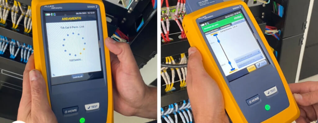
Learn what a network cable certifier is, how it differs from testers, Cat5e/Cat6/Cat6A parameters, Permanent Link vs. Channel, DSX, reports, and acceptance criteria.
Check it out!
A network cable certifier is a field test instrument used to verify whether a structured-cabling link meets the performance limits of a class or category defined by a standard. Unlike a continuity tester, it measures electrical parameters across the applicable frequency range and compares the results with normative limits, generating a compliance result and technical report.
The certifier does not simply measure “Internet speed” and does not turn a cable into Cat6 or Cat6A. It verifies the performance of the installed permanent link or channel. For the result to be valid, the correct test limit must be selected, appropriate adapters used, calibration checked, the link identified, failures interpreted, and acceptance documented.
Network Certifier vs. Tester, Verifier, and Qualifier
When the requirement is to demonstrate physical-layer performance, a continuity tester does not replace certification. The service must define the test limit, configuration, instrument, traceability, and retest criteria before measurements begin.
Not every device with an RJ45 connector is a certifier. These instruments have different functions and serve different stages of diagnosis.
| Instrument type | What it verifies | Typical result | Appropriate use |
| Continuity tester | Wire map, opens, shorts, crossed pairs | Physical connectivity | Basic installation and initial troubleshooting |
| Verifier | Continuity and basic link characteristics | Simplified diagnosis | Rapid problem location |
| Qualifier | Likely ability to support a given application | Application qualification | Operational assessment of existing networks |
| Certifier | Normative class/category parameters | PASS/FAIL against the selected test limit | Technical acceptance, warranty, and compliance documentation |
A link can pass the wire map and still fail NEXT, return loss, or insertion loss. Therefore, “all pairs are connected” does not mean the cabling is certified.
What a Network Certifier Actually Measures
For balanced cabling, certification involves a set of parameters. NBR 14565 establishes acceptance limits for cabling classes, while NBR 16869-1 addresses planning, execution, reporting, and failure handling.
| Parameter | What it represents | Associated failures |
| Wire map | Continuity and conductor sequence | open, short, reversal, split pairs |
| Length | Length elétrico do enlace | excessive route length, slack, incorrect configuration |
| Insertion loss | Signal attenuation through the channel | length, cable, temperature, connections |
| NEXT / PSNEXT | Near-end crosstalk | termination, untwisting, components |
| ACR-N / PSACR-N | Margin between signal and near-end crosstalk | combination of loss and NEXT |
| ACR-F / PSACR-F | Far-end crosstalk relationship | coupling between pairs |
| Return loss | Reflections caused by impedance discontinuities | connectors, bends, deformed cable |
| Propagation delay | Propagation time | length and cable characteristics |
| Delay skew | Delay difference between pairs | cable construction and length |
| Resistance / unbalance | Electrical behavior of conductors and pairs | termination, conductor, PoE, defects |
The instrument calculates several of these parameters across multiple frequencies. A summary report containing only “PASS” is insufficient when the objective is diagnosis, auditing, or quality traceability.
Permanent Link vs. Channel: A Choice That Changes the Test
The test configuration must represent what is being accepted.
- Permanent Link: evaluates the fixed infrastructure between termination points using dedicated adapters. It is the most common configuration for accepting the passive installation.
- Channel: includes the patch cords that are part of the operating channel and uses channel adapters.
- MPTL: where applicable, follows the configuration defined by NBR 16869-3 for links terminated directly in modular plugs.
A permanent link should not be tested with ordinary cords and then declared certified as a fixed system. The adapter is part of the metrological test configuration.
Component Category and Link Class
A common mistake is selecting “Cat6” on the instrument simply because the cable carries that marking. Certification evaluates the link, consisting of cable, patch panel, connectors, outlets, and, depending on the configuration, patch cords.
Under NBR 14565, Category 5e relates to Class D, Category 6 to Class E, and Category 6A to Class EA. For each class, the instrument uses corresponding frequency and performance limits. The wrong configuration can produce a PASS that does not answer the contractual requirement — or a FAIL against a limit that was never specified.
How to Configure the Certifier Before Testing
If the project is still in the design stage, the cabling class and acceptance configuration must originate in the technical specification. This avoids discovering at the end that the tested limit does not correspond to the contracted system.
Before the first link is tested, the test plan should define:
- applicable standard and limit;
- permanent link, channel, or MPTL;
- system category/class;
- cable type and shielding;
- link identification;
- test adapters;
- remote and main units;
- calibration status and accessory verification;
- operator and date;
- policy for PASS, FAIL, and marginal results.
This configuration should be standardized for the batch. If each technician selects different limits in the field, the reports cease to be comparable.
PASS, FAIL, and Marginal Results
The certification result is obtained by comparing the measured value with the limit corresponding to the selected frequency and configuration. The instrument may indicate the margin — or headroom — between the result and the limit.
A PASS means the evaluated parameters met the configured test limit. It does not mean that every future application will work, nor that the active network was tested. A FAIL requires diagnosis, correction, and retesting.
Results very close to the limit deserve analysis because they may reveal unstable termination, inconsistent components, or little margin. The acceptance policy should be defined before execution, especially in contracts with performance warranties.
How to Diagnose a FAIL
The failed parameter guides the investigation.
| Predominant failure | Likely causes | Field action |
| Wire map | incorrect termination, broken conductor | inspect both ends |
| NEXT | untwisting, connector, mixed components | review termination and compatibility |
| Return Loss | bends, compression, impedance, connector | inspect cable and connection points |
| Insertion Loss | length, temperature, unsuitable cable | check route, length, and material |
| Delay skew | construction/pairs, length | verify cable and installation |
| Resistance | conductor, termination, damage | review continuity, connections, and material |
Distance-based diagnostic tools help locate the responsible event, but interpretation must consider link architecture, number of connections, and installation history.
Certification of Cat5e, Cat6, and Cat6A
The certifier must cover the frequency range and accuracy required for the class being evaluated. Cat5e/Class D operates up to 100 MHz; Cat6/Class E, 250 MHz; Cat6A/Class EA, 500 MHz.
For Class EA, the project may require alien-crosstalk assessment according to the sampling plan and conditions defined by the applicable standards. This test is not simply another AUTOTEST on a single link: it evaluates the effect of disturbing links on a victim link and requires sample planning.
NBR 16869-1 establishes alien-crosstalk sampling that increases with the number of links: 10% for installations with 3 to 150 links, 15% from 151 to 3,200, and 20% from 3,201 to 35,000, under the conditions defined by the standard.
Certifier and PoE
PoE creates additional engineering requirements because current flows through the cabling pairs. Conventional transmission certification remains necessary, but remote-power projects must also consider conductor resistance, unbalance, temperature, bundling, connectivity, and voltage drop.
A Class E PASS result alone is not a declaration of thermal capacity for any PoE load. The system specification, NBR 16869-1, and component limits must be considered together.
Fluke DSX, LanTEK, and WireXpert: Examples, Not Brand Requirements
Fluke Networks DSX, TREND Networks LanTEK, and Softing WireXpert are well-known certifier families. The instrument used under a contract should be selected according to the test limit, frequency range, accuracy level, adapters, calibration, reporting capability, and traceability, not merely by brand.
The Fluke Versiv/DSX line is widely used in structured-cabling projects. Models such as the DSX-5000 and DSX-8000 have different capabilities. Model suitability must be checked against the class to be certified and the installed software/test-limit version.
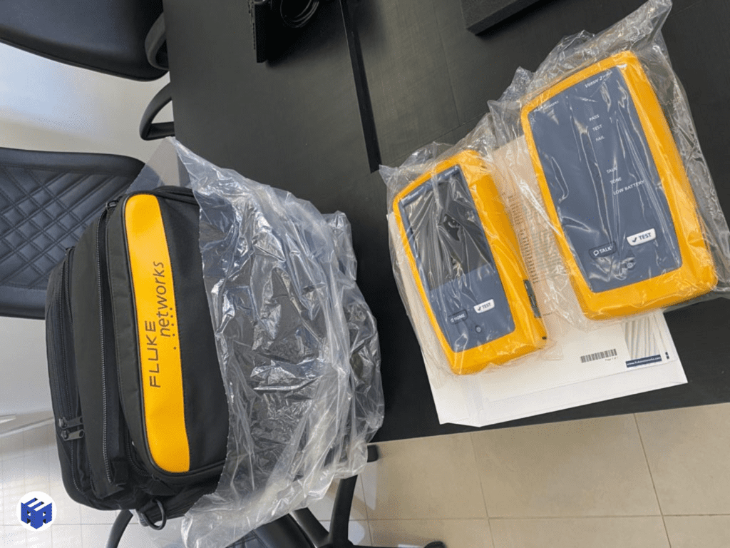
The instrument itself should not be specified as proof of quality. A high-end instrument used with the wrong limit or an unsuitable adapter produces a technically inadequate report.
LinkWare and Results Management
Software tools associated with certifiers make it possible to import results, organize projects, generate reports, and maintain traceability. The value lies in data governance: link name, building, floor, rack, patch panel, port, operator, and date should follow the same coding used in the design and As-Built documentation.
In large projects, reports without standardized naming create a second problem: hundreds of technically valid files that cannot be reconciled with drawings and port matrices.
What Should Be Included in the Certification Report
An acceptance report should allow another person to reconstruct the test. Important fields include:
- unique link identification;
- selected standard and limit;
- test configuration;
- category/class;
- cable type;
- measured length;
- results for all required parameters;
- margin and worst case where applicable;
- instrument manufacturer, model, and serial number;
- adapter identification;
- calibration/verification;
- date and operator;
- final result;
- retest history when correction was required.
Certification Is Not a Speed Test
Speedtest, iPerf, ping, and throughput measure active-network behavior and can be very useful during commissioning. They do not replace physical-layer certification. Likewise, a PASS certification does not replace validation of VLANs, PoE, DHCP, switching, Wi-Fi, or end-to-end performance.
| Test | Primary layer | What does it answer? |
| Cabling certification | Physical/passive | Does the link meet the class? |
| Application test | Physical + active | Does the Ethernet application come up on the link? |
| iPerf/throughput | Active network | What end-to-end performance is achieved? |
| Ping/latency | Active network | Is there connectivity and what is the latency? |
| PoE test | Remote power | Are voltage/power adequate? |
Certification in New Installations
In a new installation, the test plan should exist before execution. The design or technical specification must define which links will be tested, the limit, configuration, acceptable equipment, report format, failure policy, and final documentation.
Testing only at the end increases rework. A better strategy combines material receiving, inspections during installation, intermediate samples, and final certification of 100% of the links included in scope.
Certification in Retrofit and Auditing
In an existing network, the objective may be different: determine which links still support the application, locate causes of intermittency, measure margin, prepare for switch migration, assess PoE, or decide whether the cabling needs replacement.
In this scenario, it is useful to combine certification with inspection of racks, patch panels, pathways, outlets, identification, and documentation. The result should become an action plan, not merely a collection of PDFs.
How to Procure a Certification Service
A technically verifiable procurement should define:
| Requirement | What to specify |
| Scope | number of links and locations |
| Class | D, E, EA, or another applicable class |
| Configuration | Permanent Link, Channel, or MPTL |
| Instrument | compatible performance and accuracy |
| Calibration | valid, traceable evidence |
| Reports | native format + PDF where applicable |
| Failures | correction, responsibility, and retest |
| Deliverables | consolidated matrix, results, and As-Built |
| Acceptance | objective approval criteria |
Avoid specifications such as “test with Fluke.” The correct requirement is metrological performance, configuration, and documentation that allow conformity to be demonstrated.
What Engineering Adds Beyond the Instrument
Professional certification involves test planning, identification governance, result analysis, failure diagnosis, interface with design and construction, and technical recommendations for correction. In critical networks, it may also integrate commissioning and technical acceptance.
The instrument produces data. Engineering turns those data into decisions: accept, reject, correct, retest, maintain, replace, or investigate a systemic cause.
Acceptance Criteria and Failure Handling
NBR 16869-1 establishes that failed links must be repaired and retested. Documentation should maintain traceability among the result, the link, and the intervention performed.
For projects with hundreds or thousands of outlets, it is useful to consolidate indicators:
- planned total;
- total tested;
- PASS on first test;
- initial FAIL;
- corrected and retested;
- pending;
- results by floor/rack/team;
- main causes of nonconformity.
These data make it possible to identify systemic failures — for example, an improper termination technique repeated by one team — instead of treating each outlet as an isolated event.
Certification Plan: How to Structure It Before Going to the Field
In medium and large projects, certification quality depends as much on planning as on the instrument. Before the first measurement, the certification plan should turn the design into a test matrix: which links exist, where they begin and end, which class will be verified, which configuration applies, which identification should appear in the report, and what evidence will be required for acceptance.
This preparation avoids a common problem: technically valid results that are administratively useless. If the file name does not correspond to the patch-panel port, outlet, or project identifier, the report loses value for operations, maintenance, and auditing.
| Plan field | Example definition | Why it matters |
| Identification | Building-floor-rack-panel-port-outlet | Allows the test to be reconciled with the As-Built |
| Limit | Class D, E, or EA | Defines PASS/FAIL values |
| Configuration | Permanent Link, Channel, or MPTL | Defines adapters and the test boundary |
| Instrument | Compatible model/range | Ensures metrological capability |
| Failures | correct, record cause, and retest | Closes the nonconformity |
| Deliverables | native files, PDF, and consolidated matrix | Ensures future traceability |
Certify 100% or Use Sampling?
For acceptance of installed balanced cabling, engineering practice must distinguish link certification from specific tests that may use sampling. If the contract requires every outlet to be delivered to a given class, testing only a sample does not demonstrate the performance of unmeasured links. Final certification should normally cover all links within the acceptance scope.
Sampling appears in specific checks, such as alien crosstalk under defined conditions, and can also be used during construction as a process-control tool. For example, testing an intermediate batch after terminating the first racks can identify an incorrect technique before it is repeated across hundreds of outlets.
- intermediate sample testing: quality control during execution;
- final certification: individual demonstration of links within scope;
- alien crosstalk: sampling according to applicable normative criteria;
- existing-network audit: a sampling plan may be defined according to the diagnostic objective, provided it is not presented as full certification.
This distinction must appear in the report. “10% of the outlets were tested” is evidence of sampling, not a statement that 100% of the installation is certified.
Traceability: How to Relate Report, Rack, Port, and Outlet
An individual report gains value when it is part of a coherent identification system. The identifier used in the certifier should match rack labels, patch panels, drawings, port matrices, and As-Built documentation. In installations with multiple buildings, floors, and distributors, this consistency avoids ambiguity and reduces diagnostic time during operations.
A good certification matrix makes it possible to quickly answer: which outlets failed, which were retested, where they are physically located, which switch port will be associated, which outlet serves a given user, and which links remain pending. Without this structure, hundreds of PDFs do not constitute engineering documentation.
| Record | Minimum information |
| Instrument report | ID, limit, configuration, parameters, result, date, and operator |
| Consolidated matrix | ID, location, rack, panel, port, outlet, status, and retest |
| Drawing/As-Built | physical position and route or point reference |
| Rack elevation | panels, ports, and occupancy |
| Record de não conformidade | cause, correction, owner, and evidence of the new test |
How to Interpret Margin and Worst Case Without Looking Only at PASS
Two links can receive PASS and still show different behavior. One may have ample margin across all parameters; another may pass very close to the limit at a specific frequency. For normative acceptance, the correctly configured result is the reference. For diagnosis and quality management, however, margin helps identify patterns and anticipate installation problems.
If dozens of links in the same rack show a small NEXT margin, for example, the problem may not be isolated to one outlet. There may be a pattern of excessive untwisting, an unsuitable termination tool, an incompatible component, or an installation method requiring systemic correction.
- identify the parameter with the worst margin;
- check the frequency at which it occurs;
- compare links from the same batch, rack, or team;
- look for repeated behavior;
- physically inspect a representative sample;
- correct the cause before proceeding with the rest of the installation.
This statistical use of results turns the certifier into a tool for controlling installation quality, not merely a certificate generator at the end of the project.
Recurring Failures: When the Problem Is Systemic
A single failure may be a poorly terminated connector. Twenty similar failures in the same batch indicate something else. Consolidated analysis should examine failure distribution by parameter, rack, team, component, and installation stage. This pattern helps distinguish a point defect from a systemic cause.
| Observed pattern | Engineering hypothesis | Action |
| Low NEXT margin on many links | termination, untwisting, or component | review procedure and physical sample |
| Recurring Return Loss | bends, compression, connectivity, or impedance | inspect pathways and terminations |
| High Insertion Loss in one area | length, temperature, or cable batch | check routes, material, and environment |
| Wire-map failures concentrated in one team | termination method | correct process and retest the batch |
| FAIL after rack handling | patching or mechanical stress | review organization and strain relief |
Certification as Part of Commissioning and Handover
In a commissioning process, physical-layer certification is evidence within a larger system. Handover must close the relationship among what was designed, what was installed, what was tested, and what was actually delivered. This includes punch-list items, retests, identification, documentation, and acceptance criteria.
The process becomes more robust when certification is treated as a quality hold point: a link is considered complete only after installation, inspection, testing, correction of any failures, and final recording. Documentation then ceases to be an appendix produced after construction and becomes evidence of the delivery process itself.
For the owner, this reduces the risk of accepting outlets that merely show momentary connectivity. For operations, it provides a technical baseline that can be used in future interventions, expansions, and troubleshooting.
Final Considerations
A network cable certifier is a physical-layer compliance instrument, not an Internet tester. Its usefulness depends on the correct limit, suitable adapters, calibration, identification, interpretation, and documentation.
For new installations, certification should be part of the quality and acceptance plan. For existing networks, it is a diagnostic tool that helps distinguish reusable links from actual failures and guide retrofit based on technical evidence.
In projects and retrofits, certification becomes more valuable when the results support technical acceptance: failures are addressed, retests remain traceable, and the link matrix is reconciled with the As-Built and acceptance criteria.
Technical References
[1] ABNT. ABNT NBR 14565:2019 — Structured cabling for commercial buildings. ABNT, 2019. Available at: https://www.abntcatalogo.com.br/.
[2] ABNT. ABNT NBR 16869-1:2020 — Structured cabling — Part 1: Planning and installation. ABNT, 2020. Available at: https://www.abntcatalogo.com.br/.
[3] ABNT. ABNT NBR 16869-3:2022 — Structured cabling — Part 3: MPTL and direct connection. ABNT, 2022. Available at: https://www.abntcatalogo.com.br/.
[4] ISO/IEC. ISO/IEC 11801-1 — Generic cabling for customer premises — General requirements. Available at: https://www.iso.org/standards.html.
[5] ISO/IEC. ISO/IEC 14763-4 — Measurement of end-to-end links, modular plug terminated links and direct attach cabling. Available at: https://www.iso.org/standards.html.
[6] TIA. ANSI/TIA-568.2-D — Balanced Twisted-Pair Telecommunications Cabling and Components Standard. Available at: https://tiaonline.org/standards/.
Frequently Asked Questions
It is a test instrument that measures normative structured-cabling parameters and compares the results with the limits of the selected class/category, generating a PASS/FAIL compliance result and report.
A basic tester checks continuity and wire map. A certifier measures insertion loss, NEXT, return loss, and other frequency-dependent parameters and compares them with normative limits.
No. It certifies the passive physical layer. Speed and throughput tests evaluate the active network and do not replace certification.
It is the configuration used to test the fixed portion of the cabling between terminations without including user patch cords in the measurement.
It is the configuration that evaluates the complete intended channel, including the cords that are part of that connection architecture.
Suitability depends on the model’s capabilities, adapters, software, and selected limit. The contractual requirement should be metrological performance compatible with the class, not an isolated brand.
Identify the failed parameter, diagnose the cause, correct the installation, and retest. The history should remain traceable.
When the design or contract requires proof of installed-system performance, certification is the appropriate technical means to demonstrate link compliance with the specified limits.
Additional Technical Materials
Related Services
- Technical Testing and Verification
- Engineering Commissioning
- Structured Cabling Design
- Telecommunications Design
