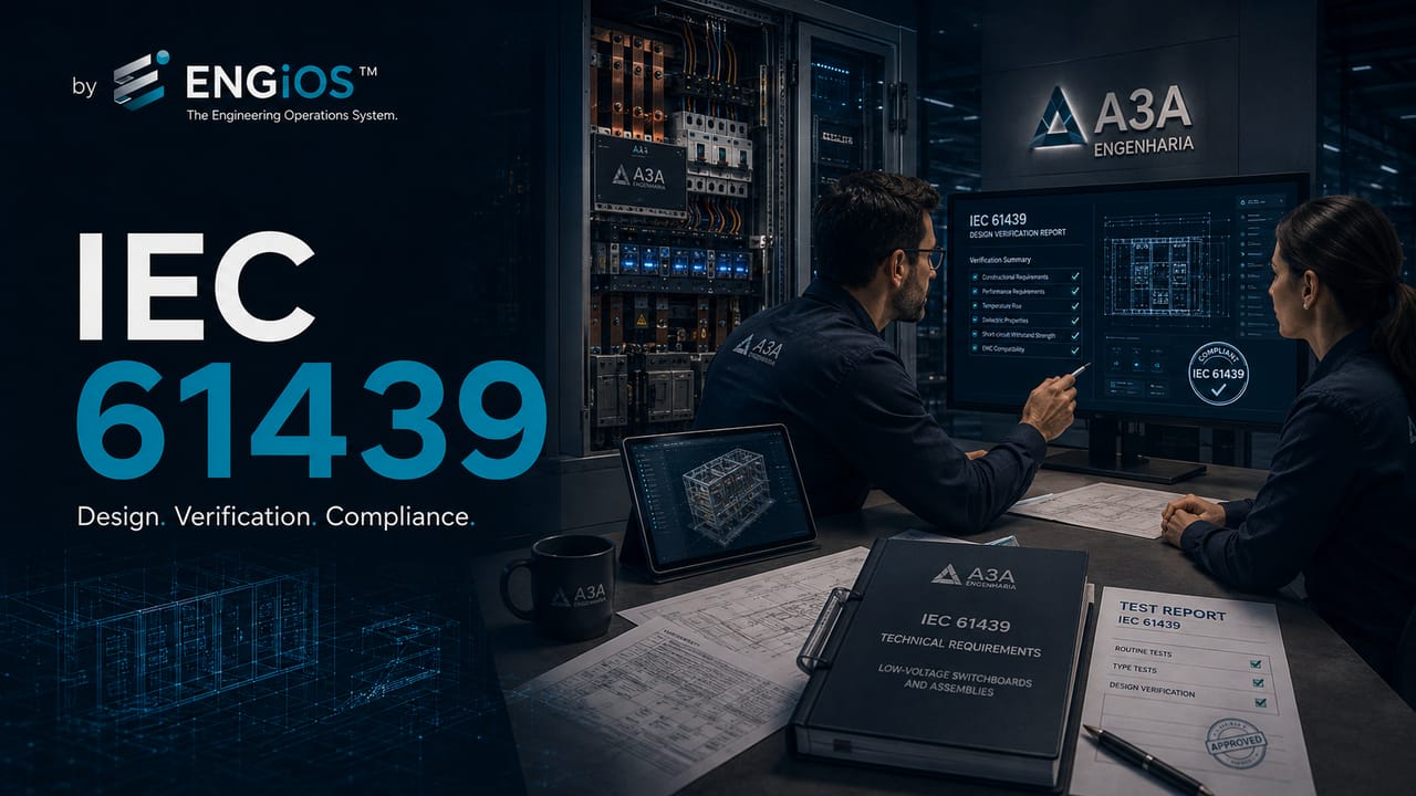
Understand how the ABNT NBR IEC 61439 series applies to main low-voltage switchboards and low-voltage panels, including specification, design verification and routine verification.
Check it out!
The ABNT NBR IEC 61439 series establishes requirements for low-voltage switchgear and controlgear assemblies, including main low-voltage switchboards and power panels. It defines how the assembly should be specified, built and verified with respect to current, temperature rise, short circuit, insulation, protection against electric shock, enclosure, connections, mechanical operation and other applicable characteristics.
The direct answer is: stating “in accordance with NBR IEC 61439” is not enough. The designer must provide the actual characteristics of the installation, and the assembler must demonstrate that the supplied assembly meets those interfaces through design verification and routine verification.
Its application requires an important distinction: the electrical installation and the assembly have related but not identical standards responsibilities. ABNT NBR 5410 addresses the low-voltage installation. The 61439 series addresses assembly performance, construction and verification.
What is ABNT NBR IEC 61439?
The standards series organizes general and specific requirements for different types of low-voltage assemblies. Its objective is to ensure that the supplied assembly has characteristics compatible with its application and that performance has been verified by defined methods.
The logic of the series avoids treating a panel as a simple grouping of components. A certified circuit breaker, suitable enclosure and independently sized busbar do not demonstrate the performance of the complete assembly.
Which parts of NBR IEC 61439 are relevant to main low-voltage switchboards?
For main low-voltage switchboards and power assemblies, three documents are especially important during specification:
| Document | Function |
| ABNT IEC/TR 61439-0 | guides the user in defining assembly characteristics |
| ABNT NBR IEC 61439-1 | establishes general rules applicable to assemblies |
| ABNT NBR IEC 61439-2 | addresses power switchgear and controlgear assemblies |
Part 0 is guidance-oriented and helps translate installation needs into technical information for the assembler. Parts 1 and 2 establish requirements and methods applicable to assembly design and verification.
Does NBR IEC 61439 replace NBR 5410?
No. The standards operate at different levels.
ABNT NBR 5410 addresses low-voltage electrical installations, including circuits, conductors, protection against electric shock and overcurrents, isolation, grounding, documentation and installation verification.
The ABNT NBR IEC 61439 series addresses the switchgear and controlgear assembly, considering enclosure, busbars, components, temperature rise, short-circuit withstand, protection against electric shock, connections and verifications.
The design must integrate both perspectives. The installation provides the application conditions; the assembly must deliver performance compatible with those conditions.
What information should the user provide to the assembler?
ABNT IEC/TR 61439-0 adopts a functional approach. The user or designer provides the application characteristics, and the assembler develops the construction solution.
The main data include:
- single-line diagram and distribution architecture;
- rated voltage and frequency;
- earthing arrangement;
- rated current of the assembly;
- incoming and outgoing circuit currents;
- expected diversity factor;
- prospective short-circuit current;
- characteristics of upstream protection;
- environment, temperature, altitude and pollution degree;
- required IP code and IK resistance;
- conductor entry, exit, material and cross-section;
- operation, access and maintenance;
- form of internal separation;
- expansion requirements;
- expected verifications and documentation.
When this information is not provided, the assembler may need to adopt default conditions or make choices that do not correspond to the actual installation need.
What are interface characteristics?
Interface characteristics are the data that connect the assembly to the installation and to its operation. They define what the main low-voltage switchboard must receive, withstand, distribute and permit throughout its service life.
They can be grouped into four blocks:
Clear definition of these interfaces prevents the assembler from adopting generic assumptions that are incompatible with the installation. It also allows proposals to be compared on the basis of performance rather than only brands, rated current and external dimensions.
The quality of the specification depends on clear definition of these interfaces.
What is design verification?
Design verification demonstrates that the assembly design meets the applicable requirements of the relevant standard.
Under the permitted conditions, verification may be performed by:
- testing;
- structured comparison with a tested reference design;
- assessment by calculation;
- application of prescribed design rules.
These methods cannot be selected freely for every requirement. The applicable standard defines where each method may be used.
The assembly manufacturer must demonstrate verification of the applied design and retain the corresponding records. When using a system developed by an original manufacturer, the assembler must respect the limits, components, arrangements and instructions supporting the reference design.
Changes to busbars, supports, enclosure, ventilation, layout, devices or connections may move the assembly outside the verified conditions. A commercial substitution is not automatically equivalent: losses, dimensions, terminals, breaking capacity, let-through energy, heating and compatibility with the reference solution must be assessed.
What is routine verification?
Routine verification is performed on each assembled unit. Its purpose is to identify material and workmanship defects and confirm that the assembly corresponds to the design and operates correctly.
It may involve testing, visual inspection and checking the original manufacturer’s instructions. Aspects assessed include:
- degree of protection of the enclosure;
- clearances and creepage distances;
- protection against electric shock;
- integrity of the protective circuit;
- incorporation of components;
- internal connections and circuits;
- terminals for external conductors;
- mechanical operation;
- dielectric properties;
- assembly functionality.
When the purchaser wants detailed records, this requirement should be stated in the specification and contract.
Do certified components guarantee compliance with 61439?
No. Component compliance is necessary, but it does not replace verification of the assembly.
The internal arrangement can change:
- temperature rise;
- current-carrying capacity;
- insulation clearances;
- short-circuit stresses;
- access and protection against contact;
- ventilation;
- device performance;
- maintenance and operational safety.
Therefore, the assessment must consider the complete panel and not only the component datasheets.
Which short-circuit characteristics appear in the 61439 series?
The specification should state the prospective short-circuit current at the assembly incoming point. The assembler defines the assembly withstand through parameters appropriate to the adopted solution.
| Parameter | Meaning in the assembly context |
| Icp | prospective short-circuit current available at the incoming point |
| Icw | short-time withstand current for the declared time |
| Ipk | peak withstand current related to dynamic stresses |
| Icc | conditional short-circuit current with a defined protective device |
These parameters should not be confused with circuit-breaker Icu or Ics. Device breaking capacity and assembly withstand are complementary verifications.
How does the standard address maintenance and expansion?
The specification should indicate how the assembly will be inspected, maintained and expanded.
Possible decisions include:
- fixed, removable or withdrawable functional units;
- access for inspection while the assembly is in service;
- maintenance with adjacent parts energized;
- internal compartments or barriers;
- empty spaces for expansion;
- partially equipped spaces;
- complete spare functional units.
The standard does not automatically assume that the assembly can be expanded while energized. When this need exists, the additional characteristics must be defined by the user.
Which documents should be required with the supply?
The documentation package should be proportional to the size and criticality of the main low-voltage switchboard. It may include:
- general drawings and diagrams;
- component list;
- rated characteristics;
- short-circuit data;
- protection settings;
- transport and installation instructions;
- operation and maintenance manual;
- routine-verification report or declaration;
- identification of design-verification references;
- final as-supplied documentation.
The objective is not to accumulate certificates without context, but to demonstrate that the delivered assembly corresponds to the specified application.
Common mistakes when applying NBR IEC 61439
The most frequent mistakes are:
- citing the standard without defining interface characteristics;
- requesting a “61439-compliant board” without diagrams and electrical data;
- confusing design verification with testing every manufactured board;
- not requiring routine verification;
- treating certified components as proof of the complete assembly;
- not stating short-circuit current and diversity factor;
- not defining environmental and maintenance conditions;
- accepting component substitutions without assessing impacts on the verified design.
Conclusion
The ABNT NBR IEC 61439 series provides a framework for specifying and verifying low-voltage assemblies. Its correct use depends on collaboration among the user, designer and assembler.
Compliance does not begin at the factory. It begins with defining the actual characteristics of the installation and ends with documentation, verification and acceptance of the supplied assembly.
Technical references
[1] ABNT IEC/TR 61439-0:2017 — Low-voltage switchgear and controlgear assemblies — Part 0: Guidance to specifying assemblies. Current international reference: IEC TR 61439-0:2022.
[2] ABNT NBR IEC 61439-1 — Low-voltage switchgear and controlgear assemblies — Part 1: General rules. See also IEC 61439-1:2020.
[3] ABNT NBR IEC 61439-2 — Low-voltage switchgear and controlgear assemblies — Part 2: Power switchgear and controlgear assemblies. See also IEC 61439-2:2020.
[4] ABNT NBR 5410 — Low-voltage electrical installations.
Frequently asked questions
It is the standards series for low-voltage switchgear and controlgear assemblies, including general requirements, specific applications and verification methods.
Yes. Main low-voltage switchboards normally fall under power switchgear and controlgear assemblies, subject to the applicable parts of the series.
Design verification demonstrates the performance of the assembly design. Routine verification is performed on each assembled unit to identify manufacturing and functional defects.
Not necessarily. The standard permits specific verification methods depending on the requirement, including testing, comparison with a reference design and assessment by defined rules.
No. The complete assembly must be designed and verified because component integration affects temperature, short circuit, insulation, protection and operation.
Additional technical materials
Related solutions
- Main Low-Voltage Switchboards and Low-Voltage Electrical Panels
- Low-Voltage Electrical Engineering
- Electrical Safety and NR-10 Compliance
Related engineering services
- Low-Voltage Electrical Design
- Short-Circuit, Selectivity and Protection Coordination Study
- Electrical Installation Inspection
- Commissioning and Acceptance of Electrical Installations
Related technical content
- Main Low-Voltage Switchboard: what it is, function and components
- Industrial Electrical Panel: types, main switchboards, distribution boards and MCCs
- Icw, Ipk and Icc in Main Low-Voltage Switchboards
- Forms of Internal Separation in Main Low-Voltage Switchboards
- Design and Routine Verification in Main Switchboards
- FAT and SAT: integrated tests and acceptance criteria
