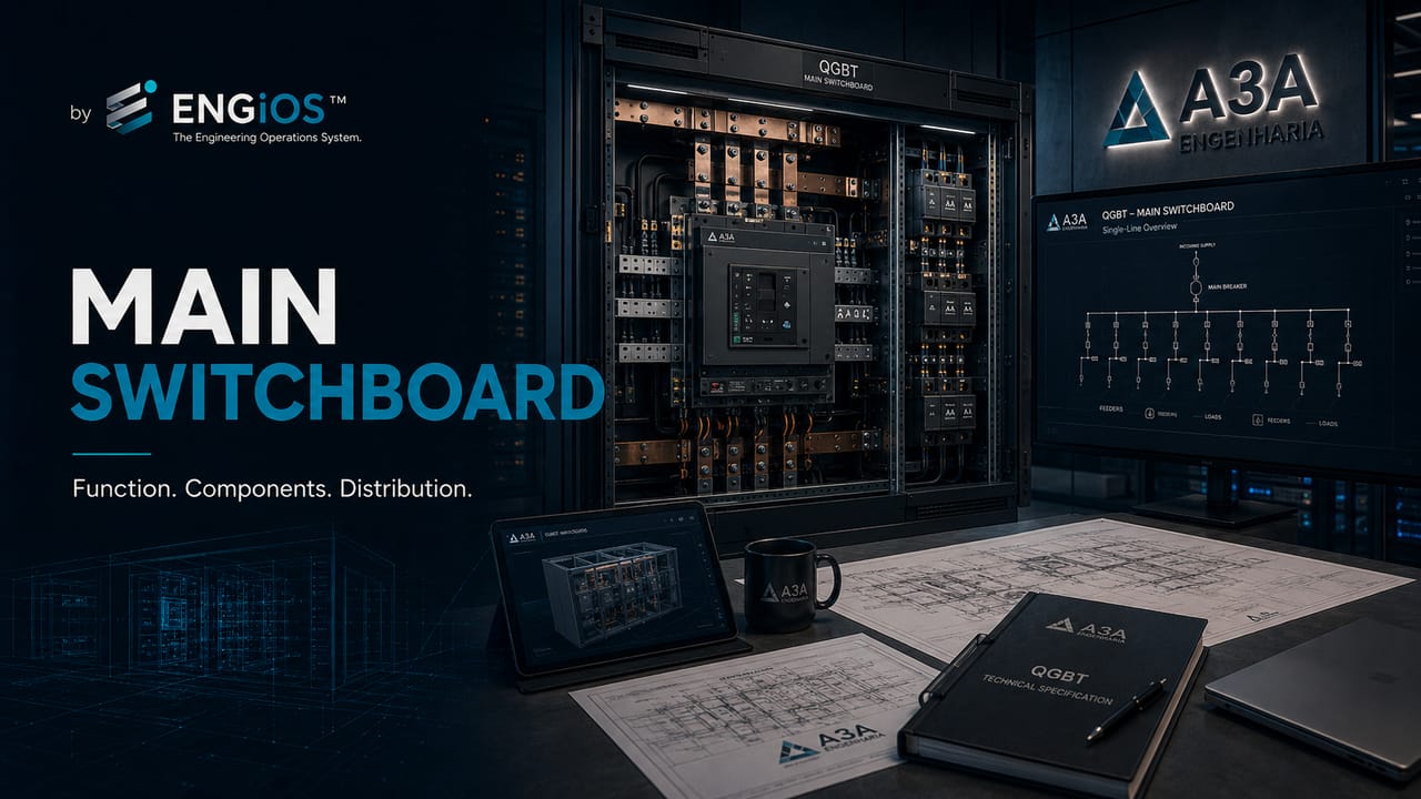
Understand what a main low-voltage switchboard is, its role in low-voltage distribution, main components, differences from other boards and standards-based specification criteria.
Check it out!
Main low-voltage switchboard is the assembly that receives one or more main low-voltage supplies and distributes power to sector boards, panels, feeders and larger loads. It concentrates functions such as isolation, overcurrent protection, busbar distribution, metering, signaling, control and integration with the grounding system.
In electrical design, the main low-voltage switchboard specification should originate from the single-line diagram, demand, design currents, earthing arrangement, prospective short-circuit currents, selectivity and operation and maintenance requirements. Simply requesting an “800 A main switchboard” does not technically define the assembly.
Although often described merely as a “large board with circuit breakers,” the main low-voltage switchboard is a complete electromechanical system. Its performance depends on compatibility among busbars, devices, connections, enclosure, protective circuit, environmental conditions and installation characteristics.
What is a main low-voltage switchboard?
The main low-voltage switchboard is the principal assembly in low-voltage distribution. It may receive power from the service entrance, the secondary of a transformer, a generator set, a UPS, renewable sources or a controlled combination of sources.
ABNT NBR 5410 defines the main distribution board as the first board after the electrical line enters the building. In installations with an on-site substation, the term main low-voltage switchboard is normally used for the power assembly installed on the low-voltage side, although the exact position depends on the architecture, delivery point and responsibility boundaries.
A typical functional sequence is: source or utility → transformation or service entrance → main low-voltage switchboard → sector boards, MCCs and panels → final circuits and loads. This position near the origin explains why the main switchboard concentrates high currents, significant short-circuit levels and functions critical to continuity.
The assembly should be understood as a verified electromechanical unit. Individually certified circuit breakers, busbars and enclosures do not demonstrate the performance of the complete assembly because internal arrangement changes temperature rise, insulation clearances, short-circuit stresses, accessibility and device behavior.
What is the function of a main low-voltage switchboard?
The primary function of the main low-voltage switchboard is to distribute power safely, continuously and under control. To achieve this, the assembly must coordinate electrical, mechanical, thermal and operational functions.
The division of the installation required by NBR 5410 is also reflected in the main switchboard: circuits should limit the impact of faults, facilitate maintenance, preserve safety services and prevent a localized event from unnecessarily taking areas or processes out of service.
| Function | Application in the assembly |
| Incoming supply | connection to transformer, service entrance, generator or another source |
| Isolation | ability to disconnect the assembly or parts of the distribution |
| Protection | overcurrent interruption and coordination with downstream devices |
| Distribution | supply of boards, panels and loads |
| Metering | monitoring voltage, current, energy, demand and power quality |
| Signaling | indication of states, alarms and operating conditions |
| Grounding and protection | integration of the PE circuit and exposed conductive parts |
| Operation and maintenance | access, switching, inspection and intervention according to design |
The main switchboard should also provide traceability. This means circuits, devices, settings, terminals, busbars and functional units must be identified and documented.
What are the main components of a main low-voltage switchboard?
The configuration varies by application, but a main low-voltage switchboard may include the following elements:
- main circuit breaker or incoming device;
- main phase, neutral and protective busbars;
- outgoing circuit breakers or devices;
- meters and electrical-quantity analyzers;
- current transformers for metering and protection;
- relays, indicators and auxiliary circuits;
- control and interlocking devices;
- terminals and terminations for external cables;
- enclosure, doors, barriers and partitions;
- natural ventilation or thermal solutions defined in the design;
- spare spaces or units for expansion.
The mere presence of these components does not prove that the main switchboard is correctly specified. Each element must be checked for compatibility with load current, voltage, short-circuit level, temperature, environment and operating strategy.
Busbars should be assessed for rated current, temperature rise, material, geometry, joints, supports and electrodynamic stresses. The neutral may require a cross-section equal to or greater than the phase conductors when nonlinear loads produce zero-sequence harmonics.
Incoming and outgoing devices must be coordinated with conductors and the short-circuit level. Rated current, trip unit, Icu, Ics, selectivity, limitation, accessories and settings form a single set of criteria.
The protective circuit must ensure continuity among the PE busbar, structure, doors and accessible conductive parts. Metering, control and communication must have auxiliary supply, protection and segregation compatible with the electromagnetic environment.
Are the main switchboard, distribution board and control panel the same thing?
No. These terms are often used imprecisely in the market, but they represent different functions.
| Type | Predominant function |
| Main low-voltage switchboard | general low-voltage distribution and protection of main feeders |
| Distribution board | distribution to specific circuits or sectors |
| MCC | motor supply, control and protection |
| Control panel | control logic, automation, signaling and process control |
| Transfer panel | switching between supply sources |
A single assembly can integrate more than one function, but this must be defined in the design. A main switchboard with generator control, source transfer or advanced supervision, for example, requires additional interfaces and verifications.
Why should a main low-voltage switchboard not be specified only by current?
Descriptions such as “800 A main switchboard” or “main board with 1,000 A circuit breaker” are insufficient. Rated current is only one of the required characteristics.
Two main switchboards with the same current can have completely different performance regarding:
- short-circuit withstand current;
- busbar capacity;
- diversity factor;
- IP degree of protection;
- IK impact resistance;
- form of internal separation;
- type of functional unit;
- maintenance and expansion capability;
- dimensions and cable entry;
- temperature and ventilation;
- documentation and verification records.
The specification must represent the actual conditions of the electrical system. The closer the main switchboard is to a transformer, the higher the available short-circuit current may be and the more critical the assembly withstand assessment becomes.
NBR 5410 requires the design to consider supplied power, the possibility of non-simultaneous operation and reserve for future expansion. In the ABNT NBR IEC 61439 series, these data relate to assembly rated current, circuit currents and the diversity factor considered in thermal verification.
The sum of the rated currents of outgoing breakers does not automatically determine the required busbar current. Empty physical space also does not demonstrate electrical expansion capacity.
Which standard applies to main low-voltage switchboards?
Main low-voltage switchboards fall within the scope of low-voltage switchgear and controlgear assemblies. The ABNT NBR IEC 61439 series establishes requirements for these assemblies.
ABNT IEC/TR 61439-0 guides users and designers on the information that must be supplied to the assembler. This includes:
- electrical-system characteristics;
- voltage and frequency;
- earthing arrangement;
- rated current of the assembly and circuits;
- prospective short-circuit current;
- environmental conditions;
- operation, access and maintenance requirements;
- conductor entry and exit;
- internal separation and expansion;
- verifications and documentation.
ABNT NBR 5410 complements this process by establishing low-voltage installation requirements, including protection, isolation, conductors, grounding, circuits and documentation.
The main switchboard should be specified by the installation and verified as an assembly
The technical white paper on main low-voltage switchboards organizes demand, current, short circuit, environment, operation, maintenance and the documentation required for acceptance.
What does it mean to treat the main switchboard as a verified assembly?
The main low-voltage switchboard is not merely an enclosure assembled with individually certified components. Assembly performance depends on how the components are integrated.
The 61439 series distinguishes design verification from routine verification.
Design verification demonstrates that the construction solution meets applicable requirements. Routine verification is performed on each assembled unit to identify material, assembly and functional defects.
This means that using reputable circuit breakers, busbars and enclosures does not eliminate the need to verify the performance of the complete assembly.
Protection and grounding must be analyzed as a system
The white paper on circuit-breaker sizing explores breaking capacity, settings and selectivity. The eBook Electrical Grounding details PE, equipotential bonding and integration of the main switchboard into the protection system.
Which information should be included in a main switchboard design?
A consistent design should provide the assembler with enough information to avoid decisions based on assumptions.
The main data include:
1. single-line diagram and distribution architecture; 2. identification of sources and loads; 3. voltage, frequency and earthing arrangement; 4. rated current and expected demand; 5. incoming and outgoing circuit currents; 6. prospective short-circuit current; 7. protection and selectivity requirements; 8. environmental conditions and location; 9. dimensions, access and cable routing; 10. operation, maintenance and expansion requirements; 11. documentation and verifications required for acceptance.
Without this information, different suppliers may present technically incomparable solutions even when they all appear to meet the commercial description.
When should a main low-voltage switchboard be inspected or reviewed?
Assessment is recommended when there are recurring trips, overheating, load expansion, missing documentation, undocumented modifications, oxidation, identification failures or doubts regarding settings and short-circuit capacity.
It is also important to inspect the main switchboard before renovations, expansions, replacement of the main breaker, generator integration, installation of new loads or issuance of technical reports.
Inspection identifies the existing condition. Design defines the solution. A technical report records conclusions and recommendations. These services are complementary and should be engaged according to the technical purpose.
Changes to the main switchboard require technical documentation
The Low-Voltage Electrical Design defines the solution and the Electrical Installation Inspection verifies the installed condition.
Conclusion
The main low-voltage switchboard is the center of low-voltage distribution in many installations. Its specification must consider the complete system: supply, loads, busbars, protection, short circuit, environment, operation, maintenance and documentation.
Treating it merely as a board containing circuit breakers increases the risk of incompatibilities, protection failures, maintenance difficulties and supply discrepancies. The correct approach begins with installation design and ends with documented verification and acceptance of the assembly.
Technical references
[1] ABNT IEC/TR 61439-0:2017 — Low-voltage switchgear and controlgear assemblies — Part 0: Guidance to specifying assemblies.
[2] ABNT. NBR 5410 — Low-voltage electrical installations.
[3] ABNT NBR IEC 60947-1 — Low-voltage switchgear and controlgear — General rules.
[4] ABNT NBR IEC 60947-2 — Low-voltage circuit breakers.
[5] IEC. IEC 61439-1:2020 — Low-voltage switchgear and controlgear assemblies — Part 1: General rules.
Frequently asked questions
QGBT means Quadro Geral de Baixa Tensão, or main low-voltage switchboard. It is the assembly that receives the main low-voltage supply and distributes power to boards, panels, feeders and loads.
The need and configuration depend on the installation architecture. Larger buildings normally have a main board or equivalent assembly to centralize primary distribution.
The main switchboard performs general distribution and normally supplies other boards and large loads. A distribution board serves more specific downstream sectors or circuits.
No. Busbars, diversity factor, temperature rise, short circuit, enclosure, connections and the assembly’s other characteristics must also be assessed.
The ABNT NBR IEC 61439 series covers low-voltage switchgear and controlgear assemblies. ABNT NBR 5410 guides application of the assembly within the electrical installation.
Additional technical materials
Related solutions
- Main Low-Voltage Switchboards and Low-Voltage Electrical Panels
- Low-Voltage Electrical Infrastructure
- Electrical Safety and NR-10 Compliance
Related engineering services
- Low-Voltage Electrical Design
- Short-Circuit, Selectivity and Protection Coordination Study
- Electrical Installation Inspection
- Commissioning and Technical Acceptance
Related technical content
- NBR IEC 61439: requirements for main switchboards and panels
- Icw, Ipk and Icc in Main Low-Voltage Switchboards
- Forms of Internal Separation in Main Low-Voltage Switchboards
- Design and Routine Verification in Main Switchboards
- Molded-Case Circuit Breaker
