
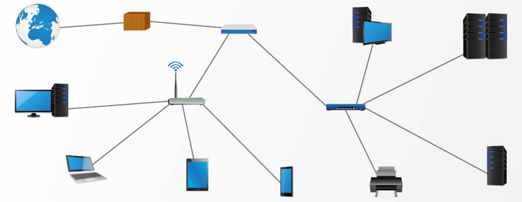
Learn how a logical network organizes IP, VLANs, subnets, routing, segmentation, services, policies, availability, documentation and testing in corporate networks.
Check it out!
Logical network is the functional architecture that determines how users, devices, systems and applications communicate over a network infrastructure. It organizes IP addressing, subnets, VLANs, broadcast domains, routing, communication policies, services such as DNS and DHCP, traffic prioritization, availability mechanisms, management, monitoring and documentation.
A network may be physically well installed and still have poor security, difficult operations, addressing conflicts, unnecessary traffic, inconsistent routes and outages caused by poorly planned logical architecture. For this reason, the logical network needs to be designed as a system, with requirements, diagrams, matrices, configuration standards and validation criteria.
What is a logical network?
The logical network describes how communication is organized, regardless of where each cable is physically installed. Two devices connected to the same switch may belong to different logical networks; likewise, devices installed on different floors or in different buildings may belong to the same logical domain when the architecture requires it.
This organization is built using mechanisms such as:
- IPv4 and IPv6 addresses;
- network masks and prefixes;
- VLANs;
- trunks and access interfaces;
- routing between subnets;
- gateways;
- VRFs where required;
- ACLs and firewall policies;
- DNS, DHCP and NTP;
- QoS;
- authentication and network access control;
- management systems, logs and telemetry;
- documentation and source of truth.
The purpose of logical design is to turn business and system requirements into a predictable architecture. The administrative network, guest Wi-Fi, servers, IP video surveillance, access control, building automation, IoT and equipment management do not need — and in many cases should not — share the same communication policies.
Logical network vs. physical network: where does one end and the other begin?
The physical network materializes connectivity: cables, fiber, racks, patch panels, fiber distribution frames, switches, routers, access points, pathways, power and other components. The logical network uses these resources to build communication domains, addressing, segmentation and policies.
The division is conceptual, not operational. Logical decisions affect the physical infrastructure and vice versa.
| Decision | Logical impact | Physical impact |
| Create a separate video surveillance network | VLAN, subnet, gateway and policies | Ports, switches, PoE and uplinks |
| Increase Wi-Fi density | SSIDs, VLANs, authentication and QoS | APs, cabling, PoE and access capacity |
| Gateway redundancy | Protocol and virtual addresses | Two devices, links and power |
| Segregate OT/IoT | Zones, ACLs/firewall and routes | Switch distribution and possible dedicated pathways |
| Faster backbone | Aggregation and routing capacity | Optics, fibers, transceivers and ports |
A logical architecture should not assume that the physical layer has unlimited capacity. Likewise, installing high-capacity physical infrastructure does not solve logical design problems.
Layer 2 and Layer 3: the boundary that organizes the network
Much of a corporate network architecture is determined by where the Layer 2 domain ends and Layer 3 routing begins.
Layer 2: switching and broadcast domains
At Layer 2, switches forward Ethernet frames based on MAC addresses. VLANs make it possible to create multiple logical domains over the same switching infrastructure.
Very large L2 domains can increase the impact of loops, broadcasts, spanning-tree failures and topology changes. This does not mean there is a universal correct VLAN size; the architecture should consider function, criticality, mobility, operations and failure domain.
Layer 3: subnets and routing
When communication needs to cross subnets, routing comes into play. The gateway may be on a Layer 3 switch, router, firewall or another platform compatible with the architecture.
The decision about where to route affects:
- traffic path;
- policy enforcement;
- latency;
- availability;
- failure domain;
- observability;
- scalability;
- troubleshooting.
In modern networks, not all inter-VLAN traffic should necessarily follow the same path. Critical systems may require firewall inspection, while high-volume internal flows may follow a different design, provided security and operational policies remain satisfied.
IP addressing plan: the foundation of a manageable network
IP addressing should not be a sequence of ranges chosen as new equipment appears. A structured plan makes it possible to identify function, location, criticality and operational responsibility.
Private IPv4 and block organization
In internal IPv4 networks, the private blocks defined by RFC 1918 are widely used. The design should reserve and subdivide addresses so growth does not create overlaps or unnecessary fragmentation.
Good decisions include:
- reserve blocks by site or region;
- separate networks by function;
- leave coherent growth space between subnets;
- avoid overlap with partner networks, VPNs and known acquisitions;
- document gateways, DHCP ranges, reservations and static addresses;
- enable route summarization where the architecture justifies it.
Subnet sizing
A subnet should be sized according to the number of devices, expected growth, broadcast behavior and operating model. Creating excessively large blocks “so IP addresses never run out” can increase the failure domain and waste addressing structure; blocks that are too small lead to frequent renumbering.
Static address, DHCP reservation and dynamic assignment
There is no single correct method for all assets. Infrastructure equipment, appliances and management interfaces often need predictable addresses. Users and mobile devices are normally well suited to DHCP. Cameras, controllers and IoT devices may use static addresses or reservations according to the organization’s operational standard.
What matters is that the strategy be documented and reproducible.
IPv6 needs to be part of the plan
IPv6 should not be treated merely as “more addresses.” It changes addressing, discovery, routing, policies, DNS, monitoring and security. Even organizations that still operate mainly in IPv4 should avoid decisions that make future adoption unnecessarily difficult.
VLANs: logical separation over shared infrastructure
VLANs make it possible to create independent Layer 2 domains over common infrastructure. They are an organization and segmentation tool, but they do not, by themselves, constitute a complete security policy.
A VLAN matrix may include:
| Function | Example policy |
| Corporate users | access to internal services and internet according to profile |
| Guests | internet without access to the corporate network |
| Servers | access controlled by application and source |
| IP video surveillance | communication with VMS, NTP, DNS and authorized workstations |
| Access control | communication with servers and required integrations |
| IoT/automation | access limited to brokers, servers and specific services |
| Management | access only from authorized workstations and teams |
| IP voice | signaling and media with appropriate QoS policies |
Access ports and trunks
An access port normally associates the end device with a specific VLAN. Trunks carry multiple VLANs between devices where needed.
The design should define which VLANs are allowed on each trunk, avoiding the practice of carrying every VLAN across the entire network without need. Reducing the logical surface of trunks simplifies operations, troubleshooting and change control.
Native VLAN and configuration inconsistencies
Configuration differences between the two ends of a link can cause unexpected behavior, traffic leakage or outages. The configuration standard should define native-VLAN handling, allowed VLANs and policies for unused ports according to the adopted platform.
Segmentation: function, risk and criticality
Segmentation is not just creating VLANs. Complete segmentation defines who may communicate with whom, through which services, under which conditions and where that policy is enforced.
A sound architecture begins with a communication matrix. For each source and destination, required flows should be known: protocol, port, direction, criticality, justification and system owner.
Flat network vs. segmented network
A flat network tends to grow without clear boundaries. This makes troubleshooting harder, increases lateral exposure and makes changes riskier.
With segmentation, failures and policies can be contained by domain. However, overly granular segmentation without governance can create hundreds of rules that are difficult to maintain. The design should balance security, operations and complexity.
Least privilege applied to the network
The principle is to allow only the communications that are necessary. A camera needs access to what is required for the VMS and infrastructure services, not necessarily to the entire user network. A guest network needs internet access, not access to internal servers.
This requires verifiable policies, not just VLAN names that suggest isolation.
Routing between networks and sites
Routing determines how prefixes are reached. Small networks may use static routes; larger or redundant networks may require dynamic protocols.
The choice should consider:
- number of networks and sites;
- convergence requirements;
- redundancy;
- operations team capability;
- summarization;
- path policies;
- integration with WAN, internet and cloud;
- observability and troubleshooting.
Gateway and high availability
If every device in a VLAN depends on a single gateway, that component may become a single point of failure. Critical architectures evaluate redundancy of gateways, equipment, links, power supplies and paths.
Redundancy should be tested. Two switches installed in a rack do not guarantee continuity if they share the same power source, the same uplink or a configuration that prevents proper convergence.
Return paths
Many failures that appear to be “firewall” or “application” problems are caused by inconsistent return paths. Troubleshooting should verify the path in both directions, especially in environments with multiple firewalls, WAN links, VPNs or load balancers.
DNS, DHCP, NTP and infrastructure services
The logical network depends on services that often do not appear on the physical diagram but are essential to operations.
DHCP
DHCP can distribute address, gateway, DNS and other parameters. The design should define scopes, exclusions, reservations, lease times and relays when the server is not on the same subnet as the client.
Pool capacity needs to match the actual client density, especially on Wi-Fi and temporary networks.
DNS
DNS is a dependency for virtually every modern application. A resolution failure may be perceived by the user as “the internet is down” even when IP connectivity is available.
Architecture and troubleshooting should consider servers, zones, forwarders, redundancy, internal/external resolution and paths to the service.
NTP
Time synchronization is essential for log correlation, authentication, certificates, security events, video surveillance and auditing. Devices with inconsistent clocks make incident investigation and event validation more difficult.
IPAM and source of truth
Isolated spreadsheets may work on small networks, but they become fragile when multiple teams change VLANs, prefixes, addresses and equipment. IPAM and source-of-truth tools help link addresses, networks, sites, equipment and interfaces to controlled records.
The tool does not fix bad data: governance and a change process are still required.
Switching, STP and link aggregation
Where redundant Layer 2 paths exist, loops must be controlled. STP, RSTP or MSTP may be part of that strategy according to the platform and architecture.
The design should define root, priorities, domains, edge protection and expected failure behavior; leaving every parameter at its default transfers architecture decisions to the equipment’s automatic behavior.
LACP and port channels make it possible to aggregate links when platforms are compatible and the design is appropriate. Aggregation should not automatically be interpreted as a linear sum of throughput for a single flow, and distribution depends on the platform’s hashing algorithm.
QoS: prioritization does not create bandwidth
QoS organizes traffic handling when resources are contested. It can classify, mark, queue, police or prioritize flows according to policy.
Voice, real-time video and delay-sensitive applications may require different treatment from bulk transfers. However, QoS does not fix permanently undersized uplinks. When capacity is structurally insufficient, the design needs to correct capacity.
A consistent policy also defines the trust boundary: where received marking is trusted, rewritten or created.
Wi-Fi is part of the logical network
SSIDs need to be associated with VLANs, authentication, addressing, policies and services. Creating too many SSIDs without need increases operational complexity and can consume airtime with management traffic.
The design should define, for example:
- corporate SSID;
- guests;
- managed devices;
- IoT where applicable;
- authentication;
- associated VLAN or policy;
- DNS/DHCP;
- permitted access;
- integration with NAC or directory;
- roaming behavior.
The RF layer and logical layer are different, but they need to be coordinated.
IP video surveillance, access control, IoT and automation
IP security and automation systems have their own traffic flows. Treating them all as “just another network port” often produces overly permissive policies.
IP video surveillance
Cameras need to reach the VMS, storage where applicable, NTP, DNS and authorized workstations. Analytics, updates and cloud services may add other flows. The matrix should reflect the real architecture.
Access control
Controllers and servers may depend on directories, databases, visitor systems, elevators, video surveillance and corporate integrations. Separating the network without mapping these dependencies causes deployment blockages.
IoT and automation
IoT devices often have update cycles, authentication and exposure characteristics different from corporate notebooks. Segregation and specific policies reduce the communication surface and simplify inventory and monitoring.
Equipment management and security plan
The management network should be treated as its own zone. Administrative interfaces for switches, routers, firewalls, controllers and UPS systems do not need to be accessible to every user.
A management standard may include:
- dedicated addressing;
- access only from administrative workstations or networks;
- SSH/HTTPS instead of insecure protocols;
- centralized AAA where applicable;
- SNMPv3 for monitoring where supported;
- central syslog;
- NTP;
- configuration backups;
- version control;
- change records;
- protection of unused ports and services.
802.1X, NAC and network access control
A VLAN does not identify who connected a device. In environments that require stronger control, 802.1X and NAC solutions can authenticate users or equipment and apply policies based on identity, posture or profile.
The architecture should account for dependencies such as RADIUS, directory, certificates, fallback for devices without a supplicant and behavior during authentication-service outages.
NAC should not be deployed merely by enabling a feature on a switch. It is an operational change that requires inventory, policy, pilot deployment, controlled exceptions and a migration plan.
Multi-site logical networks, WAN and cloud
Where multiple sites exist, the logical network needs to define how sites exchange routes, access central services and continue operating when links fail.
Design questions include:
- unique address blocks by site;
- prefix summarization;
- primary and alternate routes;
- local or centralized internet;
- VPN, private WAN or SD-WAN;
- DNS, identity and application dependencies;
- cloud access;
- internet egress policy;
- failover behavior;
- end-to-end observability.
Having two carriers does not guarantee redundancy if both circuits depend on the same physical route, CPE, power source or edge configuration.
Baseline of an existing logical network
Migrating a network without knowing its actual VLANs, prefixes, routes, policies and dependencies turns the change into discovery in production.
Technical Due Diligence organizes the baseline of the existing infrastructure and identifies documentation gaps, risks and limitations before redesign.
Before redesigning a brownfield network, it is necessary to understand what is actually in production. The logical baseline should record configurations and behavior, not just equipment.
The survey may include:
- VLANs and their uses;
- IPv4/IPv6 prefixes;
- gateways;
- routes and protocols;
- trunks;
- STP;
- port channels;
- DHCP and DNS;
- firewall rules and ACLs;
- SSIDs and policies;
- management networks;
- application dependencies;
- interface and uplink utilization;
- errors, drops and events;
- redundancy and failover behavior;
- existing documentation and gaps.
Changing a network without this baseline increases the risk of removing an invisible dependency or interrupting an undocumented flow.
Logical Network Design: from requirement to executable design
VLANs, addressing and routes need to come from an architecture, not from isolated configurations.
Logical Network Design transforms communication, availability and security requirements into diagrams, an IP plan, matrices, configuration standards, migration and acceptance criteria.
Learn about the Logical Network and Corporate Network Design service
A logical design should convert requirements into documents that enable implementation and validation.
1. Requirements and systems matrix
Identify users, applications, devices, sites, flows, criticality, security, availability and growth.
2. Target architecture
Defines L2/L3 domains, segmentation, gateways, routing, services, management and policies.
3. Addressing plan
Organizes prefixes, gateways, DHCP, reservations, infrastructure networks and growth.
4. VLAN and communication matrix
Links each segment to its purpose and specifies permitted flows between zones.
5. Configuration standard
Defines switching, trunking, STP, LACP, routing, AAA, NTP, SNMP, logging, hardening and naming principles.
6. Implementation and migration plan
Turns the architecture into change waves, windows, dependencies, tests and rollback.
7. Test and acceptance plan
Determines how to prove that segmentation, services, routing, availability and policies work according to the design.
Logical-network migration without turning change into an incident
In brownfield environments, implementation needs to preserve existing services while the architecture changes.
A controlled migration uses:
- approved baseline;
- dependency list;
- backups;
- prepared and reviewed configuration;
- change windows;
- communication plan;
- go/no-go criteria;
- pre- and post-change tests;
- executable rollback;
- record of what changed.
Large changes may be divided by building, VLAN, user group or system. The criterion should reduce the impact domain and simplify troubleshooting.
Observability: how do you know whether the logical network is healthy?
A network should not be considered healthy merely because it responds to ping. Observability combines data from different layers.
Useful indicators include:
- equipment and link availability;
- interface utilization;
- errors and drops;
- latency, jitter and loss;
- STP events and flaps;
- route changes;
- CPU and memory utilization;
- DHCP pools;
- DNS failures;
- authentications and rejections;
- firewall logs;
- PoE events;
- Wi-Fi quality;
- critical-service availability.
SNMP, syslog, telemetry, flows and APIs may contribute according to platform capability. The goal is to establish a baseline and detect deviations, not merely accumulate metrics.
Logical-network documentation and source of truth
Documentation should allow another team to understand the network without depending on the memory of the administrator who configured it.
A documentation package may contain:
| Document | Content |
| Logical diagram | sites, devices, links, zones and main services |
| IP plan | prefixes, gateways, reservations, DHCP and purpose |
| VLAN matrix | IDs, names, subnets, sites and function |
| Communication matrix | source, destination, service, direction and justification |
| Designed routing table | prefixes, protocol, summarization and paths |
| Configuration standard | conventions and minimum controls |
| Inventory | assets, interfaces, versions and location |
| Management plan | AAA, NTP, SNMP, syslog and backups |
| Test plan | scenarios, expected results and evidence |
| Logical As-Built | configuration and architecture actually accepted |
Logical documentation and actual configuration need to remain synchronized. When a change is executed without updating the source of truth, the next troubleshooting effort starts with incorrect information.
Logical-network testing and commissioning
Acceptance should prove not only that permitted flows work, but also that prohibited flows remain blocked and redundancy converges according to the requirement.
Commissioning integrates VLAN, routing, service, policy, failover, performance and documentation testing before operational handover.
Acceptance should not be limited to “the internet works.” Each requirement should have corresponding evidence.
VLAN and segmentation tests
Verify port association, trunks, allowed VLANs, gateways and isolation between networks. In addition to positive tests, there should be negative tests: proving that prohibited flows really do not pass.
DHCP, DNS and NTP
Validate address assignment, options, relay, name resolution and time synchronization from the intended networks.
Routing
Validate primary and alternate routes, summarization, paths and behavior during link or equipment loss when redundancy was a requirement.
Security and access
Test ACLs, firewall, AAA, 802.1X/NAC and access to the management plane according to scope.
Performance
Where the design has performance targets, test throughput, latency, jitter, loss and behavior under load using a methodology compatible with the requirement. The test should distinguish a network limitation from an endpoint or application limitation.
Failover and recovery
If the design promises high availability, failure should be simulated in a controlled manner. Recording convergence time and service behavior is more useful than merely confirming that “there are two links.”
Recurring failures that indicate logical-architecture problems
Some symptoms appear as isolated incidents but reveal design problems:
| Symptom | Logical hypotheses to investigate |
| Duplicate IP | manual addressing without governance, inconsistent DHCP/reservation |
| Intermittent access between networks | asymmetric route, stateful firewall, gateway or convergence |
| Excessive broadcast | large L2 domain, loop, faulty device |
| Users without IP addresses | DHCP pool, relay, VLAN or path to server |
| Name does not resolve | DNS, route, ACL, service or client configuration |
| Slow inter-VLAN traffic | uplink, firewall path, CPU, QoS or policy |
| Outage after a change | unmapped dependency, trunk, STP, route or rule |
| Camera reaches an unintended network | incomplete segmentation or permissive policy |
| Management inaccessible during failure | dependency on the same infrastructure being recovered |
Effective troubleshooting starts from evidence and compares the observed state with the expected architecture.
Cisco and other platforms: technology should follow the architecture
Cisco Catalyst, Meraki, firewalls, ISE and other platforms can implement the switching, VLANs, routing, NAC, telemetry and policies described in this article. Other manufacturers can provide equivalent functions.
The design should not begin with the equipment name. Requirements, capacity, protocols, policies, interfaces, availability and operations are defined first. It is then possible to evaluate which platforms demonstrably meet them.
In Cisco environments already deployed, specialized consulting can be useful for auditing topology, configuration, licensing, lifecycle, security and modernization opportunities without turning the design into a catalog of models.
When should the logical network be reviewed?
A review is indicated when there is disorderly growth, VLANs without a standard, overlapping IP ranges, firewall rules without traceability, flat networks, recurring incidents, expansion of video surveillance/IoT, new sites, cloud adoption, corporate Wi-Fi, core replacement, WAN changes or lack of reliable documentation.
It is also advisable to review the architecture before a major acquisition. Buying larger switches without correcting design, segmentation or availability may simply expand an inadequate architecture.
Technical checklist for evaluating a logical network
- Is there a current and controlled addressing plan?
- Is the purpose of each VLAN documented?
- Do L2 domains have coherent boundaries?
- Are gateways and routing paths known?
- Does a communication matrix between zones exist?
- Do DHCP, DNS and NTP have redundancy and documented dependencies?
- Is the management network protected?
- Do STP and LACP have an intentional design or are they simply left at defaults?
- Are there policies for AAA, logs, monitoring and configuration backup?
- Do Wi-Fi, video surveillance, access control and IoT have coherent segmentation?
- Does the multi-site architecture avoid overlapping IP ranges?
- Has redundancy been tested under failure conditions?
- Is there a performance baseline?
- Do changes have records and rollback plans?
- Does the logical As-Built match the actual deployed state?
Final considerations
A well-designed logical network turns physical infrastructure into a controlled communications platform. IP, VLANs, routing, segmentation, services, policies, availability and observability need to be treated as parts of the same architecture.
The expected result is not merely connectivity, but a network that is manageable, documented, secure, scalable and verifiable. When baseline, design, implementation, testing and source of truth remain integrated, changes no longer depend on improvisation and operations become more predictable.
Technical references
[1] IETF. RFC 1918 — Address Allocation for Private Internets. Available at: https://www.rfc-editor.org/rfc/rfc1918
[2] IETF. RFC 8200 — Internet Protocol, Version 6 (IPv6) Specification. Available at: https://www.rfc-editor.org/rfc/rfc8200
[3] IETF. RFC 2131 — Dynamic Host Configuration Protocol. Available at: https://www.rfc-editor.org/rfc/rfc2131
[4] IETF. RFC 1034 — Domain Names — Concepts and Facilities. Available at: https://www.rfc-editor.org/rfc/rfc1034
[5] IEEE 802.1 Working Group — Bridging and management standards, including VLANs and local-area networking technologies. Available at: https://1.ieee802.org/
[6] IEEE 802.3 Ethernet Working Group. Available at: https://www.ieee802.org/3/
[7] NIST. SP 800-207 — Zero Trust Architecture. Available at: https://csrc.nist.gov/pubs/sp/800/207/final
Frequently asked questions
It is the functional organization of communications over the physical infrastructure, including IP addressing, VLANs, subnets, routing, segmentation, services, policies, management and documentation.
A VLAN creates a Layer 2 logical domain. A subnet organizes addresses and communication at Layer 3. In common architectures there is an association between a VLAN and a subnet, but they are concepts from different layers.
No. A VLAN separates Layer 2 domains, but security also depends on routing policies, firewalls, ACLs, authentication, management and control of flows between segments.
Logical architecture, IP plan, VLAN matrix, communication matrix, routing, DNS/DHCP/NTP services, security policies, management, documentation, migration plan, and test and acceptance criteria.
Signs include flat networks, IP conflicts, VLANs without standards, undocumented rules, recurring incidents, difficulty expanding, overlap between sites, poor observability and absence of reliable As-Built documentation.
Because having redundant equipment or links does not prove availability. Controlled testing verifies convergence, routes, gateways, policies and the actual service impact during a failure.
Yes. IP systems need addressing, segmentation, communication policies, DNS/NTP where applicable, management and documentation like any other connected system.
Complementary technical materials
Related solutions
Related services
- Logical Network and Corporate Network Design
- Technical Engineering Due Diligence
- Telecommunications Design
- Cisco Consulting
- Owner’s Engineering
- Technical Testing
- Engineering Commissioning
- Engineering As-Built
Main content on this topic
- Network Design: stages, architecture and technical documentation
- Network Infrastructure: complete guide
- Physical Network vs. Logical Network: differences, integration and troubleshooting
