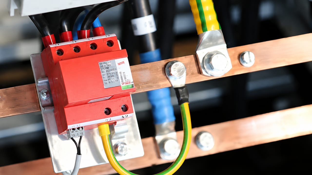
Technical article on the electrical behavior of the main components used in surge protective devices: spark gaps, gas discharge tubes, metal-oxide varistors, TVS/avalanche diodes and hybrid topologies.
Check it out!
Surge protective devices (SPDs) are boundary components: under normal conditions they should be almost invisible to the installation; during a transient they must change state within microseconds, conduct high currents and limit the voltage applied to protected equipment. This apparent simplicity hides different physical mechanisms: electric arcs in spark gaps, ionization in gas discharge tubes, nonlinear conduction in metal-oxide varistors and controlled avalanche in semiconductor junctions.
This article analyzes, at an electrical-engineering level, how the main internal elements used in low-voltage SPDs and fine signal protection operate: spark gaps, GDTs, MOV varistors, TVS/avalanche diodes and hybrid arrangements. The approach is functional and physical, connecting component behavior to the normative parameters used in design and testing, such as Uc, Up, Iimp, In, Uoc, TOV and energy coordination.
Knowing the internal technology, however, does not make simply installing the component sufficient. Actual performance depends on the protection design, the TN, TT or IT earthing arrangement, prospective short-circuit current, backup protection, grounding, equipotential bonding, integration with the LPS/SPM and connection geometry. In existing installations, recurring failures or degraded SPDs may also indicate problems in the electrical infrastructure itself, which need to be diagnosed and corrected before replacement with another device.
What an SPD actually does in the circuit
An SPD is essentially a controlled path for transient current. It is installed in parallel with the circuit or equipment to be protected, between active conductors, between an active conductor and PE, between neutral and PE, or between signal lines and a reference, according to the intended protection mode. Under steady-state conditions, the SPD should present high impedance, low leakage current and withstand the network’s maximum continuous operating voltage. During a surge, its impedance drops abruptly or progressively, creating a diversion path for impulse current.
The objective is not to “absorb” all lightning energy in the simplistic sense of the term. The objective is to limit the potential difference at the terminals of protected equipment to a value compatible with its dielectric withstand and conduct surge current through a low-impedance, low-inductance path to equipotential bonding, PE, the grounding busbar or another reference conductor.
From the testing and specification perspective, three waveforms are recurrent:
- 10/350 µs: associated with direct or partial lightning-current stresses, used to assess Class I / Type 1 SPDs and the Iimp parameter.
- 8/20 µs: associated with induced surges and switching events, used for Class II / Type 2 and the In parameter.
- 1.2/50 µs combined with 8/20 µs: used in combination-wave tests, typical of Class III / Type 3 SPDs and the Uoc parameter.
In practice, the SPD must respond to common-mode surges, where the overvoltage appears between active conductors and earth, and differential-mode surges, where it appears between active conductors themselves, such as phase-neutral or between signal conductors.
Two behavior families: voltage switching and voltage limiting
The internal components of an SPD can be classified by their electrical behavior during a surge.
Voltage-switching components
Spark gaps and gas discharge tubes are voltage-switching devices. Before triggering, they present very high impedance. When voltage exceeds a given breakdown condition, they rapidly change to a conducting state, often with a relatively low residual voltage sustained by an arc or gas discharge. This behavior resembles a switch closing during the surge.
The advantage is high impulse-current carrying capability, especially for service-entrance applications and Type 1 SPDs. The disadvantage is the need to control power-frequency follow current, that is, the current that the network may continue to supply after the surge has ended. Parameters such as follow-current extinction capability, coordination with upstream protection and short-circuit withstand are therefore critical.
Voltage-limiting components
MOV varistors and TVS/avalanche diodes are voltage-limiting devices. They do not “close” like an ideal switch. Their current rises strongly nonlinearly when voltage reaches a conduction region. The result is voltage clamping at a level that depends on current, pulse energy, temperature and component technology.
The advantage is fast response and, as a rule, the absence of sustained follow current such as that associated with spark gaps. The disadvantage is that these components dissipate energy internally and age because of thermal stress, repetitive pulses and temporary overvoltages.
Spark gaps: dielectric breakdown and controlled arc
The spark gap is the classic element for high-energy surge protection. It consists of two or more electrodes separated by a dielectric medium, usually air or gas, with geometry designed to withstand continuous operating voltage and trigger when the electric field exceeds the dielectric strength of the medium.
Under normal conditions, electrode spacing prevents significant conduction. During a surge, the electric field across the gap increases. When breakdown conditions are reached, free electrons accelerate, collide with neutral molecules and generate further ionization. This multiplication process forms a conductive channel. Voltage across the electrodes then collapses to a relatively low arc voltage while impulse current flows through the spark gap.
The dynamics of a spark gap can be divided into four phases:
- Pre-breakdown: high field, but no stable conductive channel.
- Breakdown: rapid carrier avalanche and start of discharge.
- Arc: a low-impedance ionized channel conducts surge current.
- Extinction: the channel loses ionization and the device returns to its insulating state.
The sensitive point is extinction. In a low-voltage installation, after the impulse, the power network itself may feed the discharge. This follow current is not the surge; it is source current sustaining the arc. Modern spark gaps therefore incorporate arc-extinguishing chambers, geometries that lengthen or split the arc, erosion-resistant materials and follow-current limiting mechanisms.
In Type 1 SPDs, the spark gap is valuable because it can conduct 10/350 µs currents with high charge and specific energy. In return, its coordination with fuses, circuit breakers, RCDs and downstream SPDs must be verified rather than assumed.
Gas discharge tubes, GDTs
A gas discharge tube, or GDT, is an encapsulated spark gap. Two or three electrodes are sealed in a ceramic or glass capsule containing gas at controlled pressure and composition. As long as voltage remains below the sparkover voltage, the GDT exhibits extremely high insulation resistance and very low capacitance. It is therefore common on telecommunications, data, instrumentation and signal-protection lines where parasitic capacitance cannot degrade transmission.
When applied voltage exceeds the ignition threshold, the gas ionizes and the component begins conducting. Terminal voltage falls to the arc or glow-discharge voltage, allowing relatively high impulse currents for the physical size of the device.
Three characteristics are important:
- Dynamic sparkover voltage: the steeper the waveform front, the higher the instantaneous voltage that may be required to trigger. This occurs because ionization requires finite time.
- Low capacitance: makes GDTs attractive for high-frequency signals compared with many semiconductor protective devices.
- Follow current: in circuits able to supply sufficient DC or AC current, a GDT may remain conducting after the surge and require coordination or auxiliary elements.
For these reasons, GDTs often appear in hybrid arrangements: the GDT handles the high-energy component with low capacitance, while MOVs or TVS devices reduce residual voltage and improve clamping speed.
MOV varistors: nonlinear conduction in metal oxide
The metal-oxide varistor, usually based on ZnO, is the most common element in Type 2 low-voltage SPDs and many Type 3 protective devices. Its behavior results from its ceramic microstructure. The material consists of semiconducting zinc-oxide grains separated by grain-boundary regions with barrier characteristics. It does not behave like a linear resistor; its voltage-current curve is highly non-ohmic.
A classic approximation for the conduction region is:
I = k · V^α
where α is the nonlinearity coefficient. The higher α, the more abrupt the transition from the low-leakage state to the conducting state. Under normal conditions leakage current is small. During a surge, multiple grain-boundary barriers conduct, current rises rapidly and voltage is limited to a residual level that depends on impulse current.
The MOV responds very quickly, but energy is dissipated within the ceramic volume itself. Heating occurs through the Joule effect and can be aggravated by repetitive pulses, temporary overvoltage, aging of the barriers and progressive increase in leakage current. The critical failure mode is thermal instability: temperature rises, leakage current increases, dissipation rises and the process can become self-reinforcing.
For this reason, MOV-based SPDs normally incorporate thermal disconnectors, status indicators and, depending on design, coordination with overcurrent protection. The product standard explicitly addresses overload behavior, disconnectors, indicators, TOV and failure modes.
For applications, MOVs are excellent for limiting 8/20 µs surges and forming Type 2 SPDs. They may also appear in combined Type 1 SPDs, but where the application requires conduction of partial lightning current with a 10/350 µs waveform, the architecture must be specifically designed and tested for it.
TVS and avalanche diodes: fine semiconductor protection
TVS diodes, often called avalanche diodes in surge applications, use a semiconductor junction designed to operate in a controlled manner in the reverse-breakdown region. When reverse voltage exceeds the specified value, the junction begins conducting strongly and limits the voltage applied to the protected circuit.
The mechanism may involve the Zener effect, avalanche or a transition between both, depending on breakdown voltage and doping profile. At lower voltages, Zener tunneling is more relevant; at higher voltages, avalanche multiplication dominates, with carriers accelerated by the electric field generating new electron-hole pairs through impact ionization.
A TVS is extremely fast and provides low residual voltage compared with GDTs and many MOVs. It is therefore suitable for fine protection of electronic interfaces, low-energy power supplies, communication lines, sensor inputs and digital circuits. Its limitation is energy withstand. A TVS does not replace a service-entrance SPD for lightning currents; it is a final protection stage.
Three parameters should be considered in signal circuits:
- Maximum reverse working voltage: must be above the circuit’s maximum normal voltage.
- Capacitance: may degrade fast signals, differential buses and RF.
- Clamping voltage: must be compatible with the withstand of the protected interface.
In data protection, a common approach combines a GDT for higher energy, series impedance or a decoupling element, and a TVS close to the equipment to reduce final residual voltage.
Hybrid architectures: why combine technologies?
No single component meets all requirements simultaneously. A spark gap withstands high energy but has less precise triggering and may require follow-current control. A GDT has low capacitance but may have high dynamic sparkover voltage. An MOV is fast and robust but ages because of energy and TOV. A TVS is very fast and precise but withstands less energy.
Many real SPDs are therefore hybrid. A typical arrangement distributes functions:
- First stage: spark gap or GDT to divert high current.
- Intermediate stage: MOV to limit voltage to a level compatible with the installation.
- Fine stage: TVS to protect sensitive semiconductors.
- Decoupling: inductances, resistances, line impedances or physical separation to ensure energy coordination.
Energy coordination means each stage should conduct only the portion of energy for which it was designed. If the fine stage operates before the power stage, it may be destroyed. If the power stage has excessive residual voltage, the protected equipment may fail. If there is insufficient decoupling, the devices may compete rather than cooperate.
Does the installation require a combination of Class I, II, III or different technologies across several switchboards?
The Surge Protection Measures (SPM) Design turns the selection of MOVs, spark gaps, GDTs and protection stages into an architecture coordinated with the electrical installation, grounding, equipotential bonding, LPS and protected loads.
Electrical parameters connecting component and standard
Technical SPD selection should not be based only on “kA” in a catalog. Relevant parameters describe different physical and normative limits.
- Uc: maximum continuous operating voltage that can remain applied to the SPD without undesired conduction or accelerated aging.
- Up: voltage protection level at the SPD terminals during the specified test. This quantity should be compared with equipment withstand and the overvoltage category.
- Iimp: 10/350 µs impulse current associated with Type 1 SPDs and partial lightning current.
- In: 8/20 µs nominal discharge current associated with Type 2 SPDs and repetitive tests.
- Uoc: open-circuit voltage of the combination-wave generator, associated with Type 3 SPDs.
- ISCCR: capability to withstand prospective short-circuit current in coordination with upstream protection.
- TOV: withstand to temporary power-frequency overvoltages, a critical condition for MOVs and safe failure behavior.
- Follow current: relevant to spark gaps and GDTs, as it indicates the capability to interrupt current from the network itself after the impulse.
In real installations, connection-conductor inductance can increase the voltage actually seen by equipment. Even an SPD with a good Up may provide poor protection if installed with long cables, large loops or inadequate grounding/equipotential bonding. During surges with high current rise rates, only a few centimeters of conductor can add relevant inductive voltage drop.
Disconnectors, ISCCR, follow current and status indication
ABNT NBR IEC 61643-11 treats the SPD as a complete assembly, not merely as its main nonlinear component. The product may incorporate or require internal disconnectors, external disconnectors, or both, with thermal, leakage-current and overcurrent functions. This is essential because a degraded MOV can enter thermal instability, and an SPD subjected to failure may need to be disconnected from the network before a hazardous condition is established.
ISCCR represents the maximum prospective short-circuit current for which the ratings of an SPD associated with the specified disconnector are intended. Internal technology and the backup device therefore form part of the same safety condition. In voltage-switching SPDs, follow current If and its interrupting rating Ifi may also be relevant because the power source itself can continue to feed the conductive path after the impulse.
The standard also requires operational status indication. This indication may be local and, for certain products, supplemented by an output contact for remote supervision. The indicator shows that the device or part of it no longer performs its function, but it does not by itself identify the cause of failure. TOV, current above capability, cumulative degradation, available short-circuit current, application errors and grounding or equipotential-bonding problems must be investigated separately.
For multipole devices, total discharge current ITotal can also be relevant, especially when several protection modes conduct simultaneously and the assembly takes part in lightning-related equipotential bonding.
Failure modes and aging
Every SPD should be treated as a component subject to aging. The mechanisms vary by technology.
MOVs tend to degrade through repetitive pulses, TOV, heating and increased leakage current. The design should provide thermal disconnection or another safe failure mode.
Spark gaps suffer electrode erosion, changes in triggering geometry and arc wear. Extinction capability and withstand to multiple impulses are critical points.
GDTs may undergo changes in sparkover voltage because of aging, internal contamination, electrode wear and accumulated discharges.
TVS devices can fail short, open or with parametric change when subjected to energy beyond their specification. In critical interfaces, cascaded protection is safer than relying exclusively on the semiconductor.
Visual indicators, remote contacts, periodic inspections and appropriate tests form part of the availability strategy. In critical systems, surge protection should be maintained as a safety and operational-continuity subsystem rather than treated as a disposable accessory.
Are there SPDs showing failure, recurring degradation or equipment damage even after replacements?
The Inspection, Diagnosis and Retrofit of SPDs and SPM investigates TOV, Uc, backup protection, available short-circuit current, device condition, grounding, equipotential bonding, coordination and installation changes to distinguish component end of life from a systemic cause.
Integration with LPZ, grounding and equipotential bonding
The concept of Lightning Protection Zones — LPZ organizes an installation into boundaries with different levels of electromagnetic severity. At boundaries between zones, metallic conductors, power lines and signal lines should be bonded directly or indirectly through suitable SPDs. This logic prevents the surge from crossing the installation while seeking a path through equipment.
Effective protection depends on three pillars:
- Correct SPD: technology, test class and parameters compatible with the installation point.
- Coordination: Type 1, Type 2 and Type 3 stages operating in a coherent energy sequence.
- Physical installation: short connections, adequate equipotential bonding, low inductance and compliance with the earthing arrangement.
Without adequate equipotential bonding, the SPD may conduct current but not necessarily limit the potential difference at the point that matters. In surge protection, electrical layout is part of the component.
Is the SPD correct in the catalog, but the PE, main/local bonding bar or grounding system is not technically characterized?
The Grounding Design enables verification of continuity, equipotential bonding and current paths associated with surge protection, coordinating this infrastructure with the electrical design and SPM.
Conclusion
An SPD is an engineering system condensed into a few centimeters: discharge physics, semiconductors, ceramic materials, insulation coordination, electromagnetic compatibility, grounding and test standards converge in the same device.
Spark gaps and GDTs operate through dielectric breakdown and formation of an ionized channel, making them suitable for high currents and service-entrance stages. MOV varistors operate through nonlinear conduction at grain barriers, providing good voltage limiting capability at low voltage but requiring control of aging and TOV. TVS/avalanche diodes protect the most sensitive level, with very fast response and low residual voltage but lower energy capability.
Robust protection rarely depends on a single component. It results from coordination among technologies, compliance with normative parameters and an installation that preserves low impulse impedance. During surges, physical detail determines electrical performance.
Technical note: sizing and installation of SPDs in energized switchboards should be performed by a qualified professional, with assessment of the earthing arrangement, prospective short-circuit current, overvoltage category, coordination with upstream protection and applicable normative requirements.
Technical references
[1] ASSOCIAÇÃO BRASILEIRA DE NORMAS TÉCNICAS. ABNT NBR IEC 61643-11 — Low-voltage surge protective devices — Part 11: requirements and test methods. Consult the current version in the ABNT Catalog.
[2] INTERNATIONAL ELECTROTECHNICAL COMMISSION. IEC 61643-11 — Low-voltage surge protective devices — Requirements and test methods for SPDs connected to low-voltage power systems. Consult the official publication in the IEC Webstore.
[3] INTERNATIONAL ELECTROTECHNICAL COMMISSION. IEC 62305-4 — Protection against lightning — Electrical and electronic systems within structures. Consult the official publication in the IEC Webstore.
[4] ASSOCIAÇÃO BRASILEIRA DE NORMAS TÉCNICAS. ABNT NBR 5410 — Low-voltage electrical installations. Consult the current edition in the ABNT Catalog.
[5] ASSOCIAÇÃO BRASILEIRA DE NORMAS TÉCNICAS. ABNT NBR 5419 — Protection against lightning. Consult the current series in the ABNT Catalog.
Frequently asked questions
Spark gaps operate through dielectric breakdown and conduct high impulse currents; MOVs limit voltage through nonlinear conduction and are common in low-voltage SPDs; TVS diodes provide fast, fine protection for electronic circuits but have lower energy capability.
A GDT is a gas discharge tube that remains at high impedance under normal conditions and conducts when voltage ionizes the gas. Its low capacitance makes it especially useful in telecommunications, data and instrumentation.
Each stage faces different energy levels and limiting requirements. The architecture can combine high-current-capability elements with lower-residual-voltage components to achieve energy coordination among service entrance, distribution and fine protection.
Yes. Repetitive pulses, temporary overvoltages and heating can change its characteristics and increase leakage current. MOV-based SPDs therefore normally include thermal disconnection mechanisms and status indication.
No. Performance also depends on connection impedance, the earthing arrangement, equipotential bonding and coordination among protection stages. A correctly specified SPD can provide poor protection if installed with inadequate connections.
Complementary technical materials
Related solutions
- Surge Protective Devices (SPDs)
- Surge Protection Measures
- Grounding and Equipotential Bonding
- Low-Voltage Electrical Infrastructure
Related engineering services
- Surge Protection Measures (SPM) Design
- Inspection, Diagnosis and Retrofit of SPDs and SPM
- Low-Voltage Electrical Design
- Grounding Design
- Electrical Installation Inspection
- Electrical Installation Commissioning and Technical Acceptance
Related technical content
- SPD: Surge Protection
- SPD Coordination and Selection
- Electrical Grounding
- Equipotential Bonding
- TN, TT and IT Earthing Arrangements
- NBR 5410
