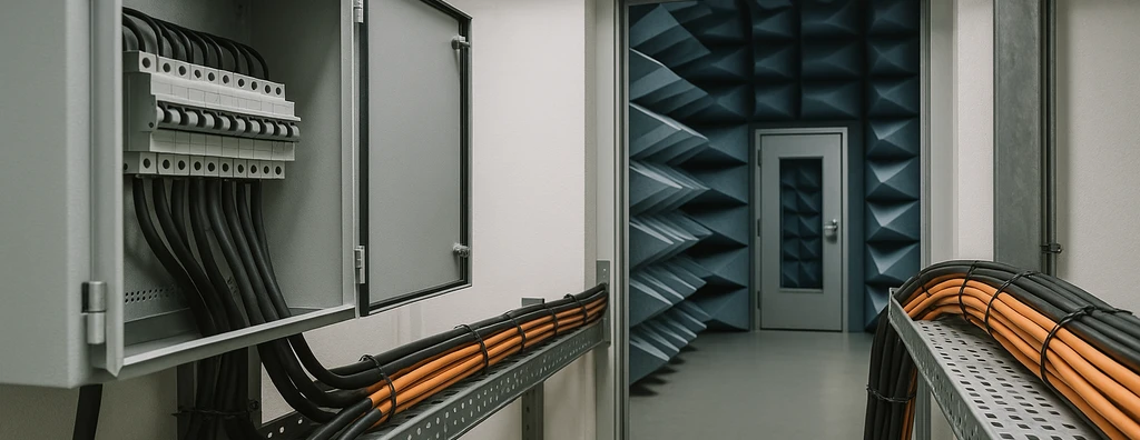
Electromagnetic compatibility in hospitals, data centers, and industrial facilities: sources, coupling, grounding, shielding, segregation, SPDs, and validation.
Check it out!
Critical environments concentrate systems whose failure can compromise safety, operational continuity, data, production, or service delivery. Hospitals, data centers, laboratories, operations centers, airports, and industrial plants require a more rigorous approach to electromagnetic compatibility (EMC) than simply selecting individually compliant equipment.
The installation needs to control emissions produced by electrical and electronic sources and preserve the immunity of sensitive systems. The Electromagnetic Compatibility and Interference Control solution integrates electrical distribution, UPS systems, generators, panels, automation, networks, electronic security, grounding, lightning protection, cabling, HVAC, and metallic infrastructure.
In highly critical environments, an intermittent failure can be as relevant as permanent damage. Resets, momentary communication loss, sensor errors, or unintended actuation may last only milliseconds and still interrupt essential processes.
What Characterizes a Critical EMC Environment?
Criticality does not depend only on the number of devices. It results from the combination of failure consequences, system sensitivity, technology density, diversity of disturbance sources, and difficulty of recovery.
An environment may be considered critical when it presents one or more of the following conditions:
- systems that cannot tolerate perceptible interruption;
- medical, laboratory, or safety/security equipment;
- continuous or automated industrial processes;
- high concentration of servers, switched-mode power supplies, and converters;
- long signal and instrumentation lines;
- integration between different buildings;
- proximity to motors, drives, transformers, or antennas;
- dependence on communication networks for command and supervision;
- high impact of false or intermittent failures.
The analysis should begin with system function and minimum acceptable performance, not merely installed electrical power.
Difference between Product EMC and Installation EMC
Equipment tested according to an emissions and immunity standard was evaluated under defined laboratory conditions. In the real installation, its performance also depends on cables, interfaces, panels, power sources, grounding, shielding, thermal environment, and proximity to other loads.
Product compliance is necessary but not sufficient to guarantee system operation. Suitable equipment may fail when installed with excessively long cables, different reference potentials, interrupted shielding, disturbed power supplies, or interfaces exposed to levels higher than those considered in qualification.
Likewise, field tests on an installation do not replace laboratory product certification. The report should clearly state what was verified and which limitations remain.
For the general concepts of EMI, emissions, immunity, and coupling, see Electromagnetic Compatibility (EMC): What It Is, EMI, Causes, and Solutions.
Main Disturbance Sources in Critical Environments
Electrical Distribution and Panels
Transformers, busbars, circuit breakers, contactors, relays, and switching operations produce fields and transients. Panel location, separation between power and control, and internal assembly organization directly affect the electromagnetic environment.
The ABNT NBR IEC 61439 series includes electromagnetic-compatibility requirements for low-voltage assemblies. Final performance, however, also depends on assembly construction, installed devices, cable entries, and external connections.
Variable-Frequency Drives, Motors, and Drives
Variable-frequency drives use fast switching and can produce common-mode currents, harmonics, and high-frequency components. Long motor cables, inadequate shielding, and high-impedance protective connections increase propagation.
Starts, braking, and operating-state changes may coincide with failures in sensors, industrial networks, and controllers. Investigation needs to correlate the symptom with drive operating state rather than merely with the physical presence of the VFD.
UPS Systems, Switched-Mode Power Supplies, and IT Equipment
Data centers, operations centers, and telecommunications facilities concentrate rectifiers, switched-mode power supplies, and UPS systems. These devices can generate distortion while also being sensitive to voltage sags, transients, and conducted disturbances.
The Power for Critical Infrastructure architecture should consider compatibility among UPS systems, generators, distribution, grounding, bypass arrangements, and electronic loads.
Radio Frequency and Antennas
Transmitters, radios, wireless networks, and antennas produce intentional fields. Assessment should consider power, frequency, distance, direction, cabling, and immunity of nearby equipment.
Roof-mounted antennas also interact with the lightning protection system, metallic lines, and internal systems. Routing, equipotential bonding, surge protection, and separation distance need to be coordinated.
Lightning
Direct or nearby lightning can produce conducted surges, induced voltages, and intense magnetic fields. ABNT NBR 5419-4:2026 uses Lightning Protection Zones and Surge Protection Measures to progressively reduce this threat.
The article on NBR 5419-4:2026, LPZs, and MPS details this architecture.
Especially Sensitive Systems
Hospitals and Laboratories
Medical equipment, monitoring systems, clinical networks, and building automation may have different immunity levels and different failure consequences. Technical rooms, safety power supplies, grounding, routes, and interfaces should be coordinated with the specific requirements of the equipment and care environment.
The presence of equipment that generates intense fields requires analysis based on manufacturer requirements and installation design. Shielding or separation solutions should not be generalized without considering frequency, intensity, and area of influence.
Data Centers
High power density, redundant sources, and cable concentration make data centers dependent on consistent equipotential bonding. A and B paths should not share hidden single electromagnetic points of failure such as the same route, the same reference busbar, or the same unprotected metallic interface.
UPS systems, generators, panels, cooling, racks, and cabling need to be analyzed as a single architecture. Physical separation should be compatible with redundancy, maintenance, and EMC performance.
Industrial Plants
Industrial environments combine motors, drives, welding, panels, instrumentation, and control networks. Failures may appear only under specific operating conditions such as start-up, braking, recipe changes, or high-load operation.
The design should separate power, control, instrumentation, and communications, reduce loop areas, use suitable interfaces, and document shield terminations. Optical fiber can eliminate metallic paths in critical interconnections, but it does not solve power-supply and equipotential-bonding problems at the endpoints.
Airports and Operations Centers
These environments integrate communications, surveillance, automation, access control, information systems, radio, and critical power. Unavailability can result from interaction among systems that function correctly in isolation.
EMC management should include an interface matrix, routes, zones, sources, immunity requirements, and responsibilities among suppliers.
How Do Coupling Mechanisms Manifest?
Conducted Coupling
The disturbance propagates through power, signal, reference, shielding, or protective conductors. Equipment connected to two different networks can form a path between different equipotential references.
Capacitive Coupling
The electric field transfers energy between nearby conductors. Parallel length, distance, voltage, and frequency influence capacitance and coupled current.
Inductive Coupling
Time-varying currents produce magnetic fields that induce voltage in nearby loops. Reducing loop area, keeping outgoing and return conductors close together, and using twisted pairs are important measures.
Radiated Coupling
Cables, openings, structures, and enclosures can behave as antennas. At high frequencies, small discontinuities and long connections can compromise shielding.
Grounding and Equipotential-Bonding Architecture
Protective grounding and functional reference need to be addressed in a coordinated manner. Creating independent electrodes to “isolate noise” can increase potential differences and force currents through communication cables.
Racks, panels, cable trays, structures, shields, and busbars should form a coherent equipotential-bonding network. For fast phenomena, connection geometry and impedance are as important as resistance measured at low frequency.
In critical environments, documentation should show bonding points, conductor cross-sections, routes, busbars, and interfaces among disciplines.
Segregation and Routing
Separation between power and signal should be defined from the disturbance source, sensitivity, and cable characteristics. A fixed distance does not apply equally to a lighting circuit, a motor feeder, and a VFD cable.
The design should consider:
- length of parallel runs;
- source current and frequency;
- cable construction and shielding;
- compartments and barriers;
- route crossings;
- proximity to busbars and transformers;
- lightning-protection-system current paths;
- transitions between electromagnetic zones.
Changes made during construction need to be analyzed before the new route is accepted as equivalent to the design route.
Shielding and Terminations
Shielding effectiveness depends on continuity, coverage, frequency, and termination. A narrow, long connection may work at low frequency and present high impedance to fast transients.
Shielded cables require compatible connectors, panels, and equipment. The strategy of connecting one or both ends depends on the application, frequency, equipotential architecture, and manufacturer guidance; it should not be turned into a universal rule.
Shielded panels and rooms also require treatment of doors, openings, ventilation, and cable entries. Every penetration can reduce barrier performance.
Power Quality and EMC
Voltage sags, interruptions, harmonics, imbalance, and transients can cause failures in critical equipment. However, not every communication or instrumentation problem appears on a conventional power-quality analyzer.
The Power Quality Analysis and Diagnosis service helps distinguish power-supply events from localized common-mode, shielding, reference, or radiated-coupling problems.
Simultaneous measurement campaigns at different points help determine whether the disturbance originates from the supply, internal distribution, or a specific load.
Surge Protection for Power and Signal Lines
SPDs need to be coordinated with equipment withstand capability, protection zones, and conductor lengths. Protecting only the power supply may leave an entry path through data, automation, telephony, or antenna lines.
The Surge Protection Measures solution integrates SPDs, equipotential bonding, shielding, routing, and isolating interfaces.
For equipment connected to two services, connection points and voltages between ports need to be analyzed together.
Diagnosis of Intermittent Failures
The Electromagnetic Interference Diagnosis and Mitigation service builds a common timeline between failures and operating conditions. Automation records, alarms, switching operations, starts, transfers, power quality, and communication logs need to be synchronized.
A recommended sequence is:
1. define the symptom and failure criterion; 2. identify when and under which operating modes it occurs; 3. map sources, routes, and interfaces; 4. identify recent changes; 5. measure at points capable of separating origin from propagation; 6. test hypotheses in a controlled manner; 7. implement corrections in stages; 8. verify the result using the same initial indicator.
Sporadic failures may require extended monitoring. Isolated readings rarely support definitive conclusions.
Commissioning and Integrated Testing
Commissioning should verify that the design was preserved during construction. Continuity of metallic infrastructure, equipotential bonding, segregation, shield terminations, SPD locations, and routes need to be inspected.
Functional tests should reproduce relevant events such as motor starts, source transfers, drive operation, load switching, and mode changes. The objective is to observe whether communications, sensors, video, alarms, and controls maintain the expected performance.
The Electrical Installation Commissioning and Technical Acceptance service can integrate these checks with the installation’s other tests.
Required Documents
EMC management in critical environments may produce:
- map of sources and sensitive systems;
- interface matrix among disciplines;
- emission and immunity criteria;
- segregation and routing drawings;
- equipotential-bonding design;
- shielding and termination details;
- coordination of SPDs on power and signal lines;
- installation procedures;
- test and commissioning plan;
- diagnostic report;
- mitigation plan;
- records of changes and as-built condition.
Documentation needs to remain current whenever equipment, routes, or operating modes are modified.
Conclusion
Electromagnetic compatibility in critical environments depends on coordination among electrical architecture, infrastructure, equipment, networks, and operations. Individually compliant products can fail when interfaces and the environment do not preserve their immunity conditions.
An effective approach identifies sources, coupling paths, and sensitive systems; defines equipotential bonding, segregation, shielding, and surge protection; and demonstrates the result through inspections and integrated testing.
The earlier these requirements are incorporated into the design, the lower the dependence on later corrections, trial-and-error replacements, and outages for investigation.
Technical References
[1] ABNT. NBR 5410:2004 — Low-voltage electrical installations.
[2] ABNT. NBR 5419-4:2026 — Protection against lightning — Electrical and electronic systems within the structure.
[3] ABNT. NBR IEC 61439-1:2016 — Low-voltage switchgear and controlgear assemblies.
Frequently Asked Questions
The combination of failure consequences, system sensitivity, technology density, diversity of disturbance sources, and difficulty of recovery.
No. Product compliance is important, but cables, interfaces, grounding, power sources, panels, and proximity to other loads can change the real environment.
In addition to power-supply disturbances, common points between redundant paths, potential differences, shielding problems, and failures in metallic interfaces need to be avoided.
Fast switching can produce high-frequency and common-mode currents that propagate through cables, structures, and reference paths, affecting sensors, networks, and controllers.
The choice depends on the system standard, environment, frequency, route, and equipotential bonding. Incorrectly installed shielded cable may not provide the expected benefit.
Power quality evaluates power-supply phenomena. EMC also includes signal noise, common-mode effects, radiated fields, and coupling between equipment.
Through construction inspection, measurements compatible with the phenomenon, and functional tests that reproduce starts, switching operations, transfers, and relevant operating modes.
No. Field testing evaluates the installation and its interfaces; product certification requires specific laboratory methods and conditions.
